is a passive element of an electrical circuit that has a certain or variable value of electrical resistance. Unlike active elements, passive elements do not have the ability to control the flow of electrons.
Resistors are popularly called “resistors” or simply “resistance”. Resistors are responsible for linearly converting current into voltage and vice versa, as well as for limiting current and absorbing electrical energy.
Resistor is one of the most popular components and is used in most electronic devices.
Why is a resistor needed in an electrical circuit?
A clear example of how a resistor works
Using a resistor in an electrical circuit, the current is limited, obtaining its desired value. According to Ohm's law, the greater the resistance at a stable voltage, the less the current.
Ohm's law is expressed by the formula U = I*R, in which:
- U – voltage, V;
- I – current strength, A;
- R – resistance, Ohm.
Also resistors work as:
- current to voltage converters and vice versa;
- voltage dividers, this property is used in measuring devices;
- elements to reduce or completely remove radio interference.
Marking of SMD resistors
Digital marking
Let's look at the markings of SMD resistors. Resistors of size 0402 (size values here) are not marked. The rest are marked with three or four numbers, since they are a little larger and you can still put numbers or some kind of marking on them. Resistors with a tolerance of up to 10% are marked with three digits, where the first two digits indicate the value of this resistor, and the last third digit is 10 to the power of this last digit. Let's look at this resistor:
The resistance of the resistor shown in the photo is 22x102 = 2200 Ohms or 2.2 K.
Let's check if this is true? We take this tiny SMD component between the probes and measure the resistance.
Resistance 2.18 kOhm. A small error does not count.
SMD resistors with a tolerance of 1% and size 0805 and larger are marked with four numbers. For example, a resistor with the number 4422. This is calculated as 442x102 = 44200 Ohm = 44.2 kOhm.
There are also SMD resistors with almost zero resistance (there is still a very, very small resistance) or simply so-called jumpers. They look more aesthetically pleasing than any wires.
Main characteristics of resistors
The parameters that need to be taken into account when choosing a resistor depend on the nature of the circuit in which it will be used. The main characteristics include:
- Nominal resistance.
This value is measured in Ohms, 1 kOhm (1000 Ohms), 1 MOhm (1000 kOhms), 1 GOhm (1000 MOhms). - Maximum power dissipation
is the maximum power that an element is capable of dissipating during long-term use. In the diagrams, the rated dissipation power is indicated only for powerful rechargers. The higher the power, the larger the part size. - Accuracy class.
Determines how much the actual resistance value may differ from the declared value.
If necessary, take into account the maximum operating voltage, excess noise, resistance to temperature and moisture, and voltage factor. If the part is planned to be installed in a device operating at high and ultra-high frequencies, parasitic capacitance and parasitic inductance must be taken into account. These values should be minimal.
Classification of resistors
Resistors differ not only in their ability to adjust resistance. They can be made from different resistive materials, have different numbers of contacts, and have other features.
By type of resistive material
The elements can be wire, non-wire or metal foil. High-resistance wire is a feature of a wire element; alloys such as nichrome, constantan or nickel are used for its manufacture. Films with increased resistivity are the basis of non-wire elements. Metal foils use special foil. Now let's find out what resistors are made of.
Semiconductor design
Non-wire are divided into thin-layer and composite, the thickness of the former is measured in nanometers, and the latter in fractions of a millimeter. Thin-layers are divided into:
- metal oxide;
- metallized;
- borocarbons;
- metal-dielectric;
- carbonaceous.
Composite ones, in turn, are divided into volumetric and film. The latter can be with an organic or inorganic dielectric. To understand whether a resistor has polarity, you should know that their sides are identical.
By purpose resistance
Permanent and variable semiconductors also have some differences in characteristics. Permanent ones are divided into general and special purpose conductors. The latter may be:
- high frequency;
- high voltage;
- high-megaohm;
- precision.
Such parts are used in precision measuring instruments; they are particularly stable.
Variable resistors can be divided into trimming and adjusting. The latter can be with a linear or nonlinear functional characteristic.
By number of contacts
Depending on the purpose of the resistor, it may have one, two or more contacts. The contacts themselves are also different, for example, for SMD resistors it is a contact pad, for wire resistors it is a special wire composition. There are metal film resistors with quantum point contacts, and in variables they are moving.
Different number of contacts on elements
Other
Resistors differ in the shape and type of resistance, as well as in the nature of the dependence of the resistance value on voltage. The description of the dependence of a quantity can be linear or nonlinear. Using the element is simple, the capacity is indicated on the body, minus and plus are the same.
Resistors may or may not be sealed against moisture, and the housing may be varnished, vacuum sealed, sealed, pressed into plastic, or compounded. Nonlinear ones are divided into:
- varistors;
- magnetoresistors;
- photoresistors;
- posistors;
- strain gauges;
- thermistors.
They all perform their specific function, some change resistance based on temperature, others on voltage, and others on radiant energy.
Installation method
According to installation technology, resistors are divided into output and SMD.
Output resistors
Radial output resistor
Axial output resistor
Designed for installation through a printed circuit board. The leads can be located axially or radially. Such parts were used in old audio and video equipment. Now they are used in simple devices and in cases where the use of SMD resistors is impossible for some reason.
The design of output resistors can be made of wire, metal film or composite.
What does a wirewound resistor consist of?
In wirewound resistors, the resistive component is a wire wound around a core. Bifilar winding (two parallel wires insulated from each other, or a regular two-core wire) reduces parasitic inductance. Leads made of stranded copper or brass plates are connected to the ends of the winding. To protect against moisture, mechanical damage and contamination, wire cuts are coated with inorganic enamel that is resistant to elevated temperatures.
What is the difference between a metal film resistor and a wirewound resistor?
In a metal film resistor, the resistive element is not a wire, but a film made of a metal alloy. The resistive components (wire or film) in the resistor are made of alloys with high resistivity: manganin, constantan, nichrome, nickel.
SMD resistors
SMD resistors (or chip resistors) are designed for surface mounting and do not have pins. These miniature parts of low thickness are made in rectangular or oval shapes. They have small contacts soldered into the surface. Their advantages are saving space on the board, simplifying and speeding up the board assembly process, and the ability to use them for automated installation.
SMD resistors are manufactured using film technology. They can be thin- or thick-film. A resistive thick or thin film is applied to an insulating substrate. The substrate performs two functions: a base and a heat-removing component.
What are chip resistors made of?
Thin-film elements, which have special requirements for moisture resistance, are made of nichrome. In the production of thick-film models, ruthenium dioxide, lead and bismuth ruthenites are used.
What you need to know about resistors?
Resistor: A piece of material that resists the passage of electric current. Terminals are attached to both ends. That's all. What could be simpler?
It turns out that this is not at all simple. Temperature, capacitance, inductance and other parameters play a role in making a resistor a rather complex component. And there are many different ways to use it in circuits, but we will focus on the different types of fixed value resistors, how they are made and how they can be useful in different cases.
Let's start with the simplest and oldest.
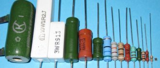
Carbon composite in the turntable
They are often called "old" resistors. They were widely used in the 1960s, but with the advent of other types of resistors and due to their relatively high cost, their use is now limited. They consist of a mixture of ceramic powder and carbon bonded with resin. Carbon conducts current well, and the more of it in the mixture, the less resistance. The wires are connected from the ends. They are covered with paint or plastic to serve as insulation, and resistance and tolerance are indicated by colored stripes.
The resistance of such resistors can be permanently changed by exposing them to high humidity, high voltage, or overheating. The tolerance is 5% or more. It's just a solid cylinder with good high frequency response. They also tolerate overheating well, despite their small size, and are still used in power supplies and welding controllers.
However, their age did not stop me from using a bag of these resistors that I bought at a thrift store for the purpose of making various resistors that I needed for my music project. player 555. The photo shows just my craft.
They are produced by applying a layer of pure carbon to a ceramic cylinder and then removing the carbon to form a spiral. The result is covered with silicon. The thickness of the layer and the width of the remaining carbon control the resistance, and the tolerance of such resistors can be from 2%, better than the previous ones. Thanks to pure carbon, resistance changes less with temperature.
The temperature coefficient of resistance of carbon film resistors ranges from 200 to 500 ppm/C - parts per million per degree Celsius. 200 ppm/C means that with each degree the resistance will not change by more than 200 ohms for each megohm of total resistance. As a percentage, this can be expressed as 0.02%/C. If the temperature changes by 80 C, at 200 ppm/C the resistor resistance will change by 1.6%, or 16 kOhm.
Such resistors are available in nominal values from 1 Ohm to 10 kOhm, with powers from 1/16 W to 5 W and can withstand voltages of several kilovolts. Commonly used in high voltage power supplies, X-ray machines, lasers and radar.
Metal film is made in a similar fashion to carbon, by placing a metal layer (often nickel-chromium) on ceramic, then cutting out a spiral. According to documentation from the manufacturer Vishay, after attaching the terminals, the spiral was previously processed by grinding, but now lasers are used for this. The result is varnished and marked with color coding or text.
The resistance of metal film resistors varies less than that of carbon film resistors. TCS is in the region of 50-100 ppm/C. 50 ppm/C is the same as 0.005%/C. Using a similar example to the above with a 1 MΩ resistor, a change in temperature of 80 C will result in a resistance change of 0.4%, or 4 kΩ, in the case of a 50 ppm/C resistor.
Their tolerance is less, about 0.1%. They also have good noise characteristics, low nonlinearity and good time stability, and are used for many purposes.
The case is similar to a metal film, only tin oxide with an admixture of antimony oxide is usually used. Such resistors behave better than carbon or metal films when it comes to voltage, overloads, surges and high temperatures. Resistors on carbon film operate up to 200 C, on metal - up to 250-300 C, and resistors on oxide film - up to 450 C. At the same time, their stability is very poor.
They are made by winding wires onto a plastic, ceramic or fiberglass cylinder. Since the wire can be cut quite accurately, their resistance value can be selected with great accuracy with a tolerance of no worse than 0.1%. To get a high resistance resistor, you need to use a very thin and long wire. The wire can be made thinner for less power or thicker for more power. It can be made from a wide range of metals and alloys, including nickel, chromium, copper, silver, chromium steel and tungsten.
They are developed with an eye to the ability to operate at high temperatures: tungsten ones can withstand temperatures up to 1700 C, silver ones - from 0 to 150 C. TCR for high-precision wirewound resistors is about 5 ppm/C. Resistors designed for high powers have a higher TCR.
They operate at powers from 0.5 W to 1000 W. Resistors of several hundred watts can be coated with high-temperature silicon or vitreous enamel. To increase heat dissipation, they can be equipped with an aluminum casing with plates that act as a radiator.
Types of winding
Since they are practically coils, they have inductance and capacitance, which makes them behave poorly at high frequencies. To reduce these effects, various clever winding schemes are used, such as bifilar winding, flat carrier winding, and Airton-Perry winding.
Bifilar winding has no induction, but high capacitance. Winding on a flat and thin medium brings the wires closer together and reduces induction. Airton-Perry winding, due to the fact that the wires go in different directions and are close to each other, reduces self-inductance and capacitance, since the voltage is the same at the intersection points.
Potentiometers are made using wirewound resistors due to their reliability. They are also used in circuit breakers and fuses. Their inductance can be increased and used as current sensors by measuring inductive reactance.
They use foil several microns thick, usually made of nickel-chromium with additions, located on a ceramic substrate. They are the most stable and accurate of all, even though they have been around since the 1960s. The required resistance is achieved by photo-etching the foil. They have no inductance, low capacitance, good stability and fast thermal stabilization. The tolerance can be within 0.001%.
TCS is 1 ppm/C. When the temperature changes by 80 C, the megaohm resistor will change its resistance by only 0.008% or 80 Ohms. The way in which such precision is achieved is interesting. As the temperature increases, the resistance also increases. But the resistor is made in such a way that an increase in temperature causes the foil to shrink, causing the resistance to drop. The overall effect is that the resistance remains almost unchanged.
Well suited for audio projects with high frequency currents. Also suitable for projects requiring high precision, such as electronic scales. Naturally used in areas where large temperature fluctuations are expected.
Mainly used for surface mounting. The film in thick-film resistors is 1000 times thicker than in thin-film resistors. These are the cheapest resistors, since thick film is cheaper.
Thin-film resistors are manufactured by ion sputtering of nickel-chromium onto an insulating substrate. Then photo-etching, abrasive or laser cleaning is applied. Thick film ones are made by stencil printing. The film is a mixture of binder, carrier and metal oxide. At the end of the process, abrasive or laser cleaning is applied.
The tolerance of thin-film resistors is at the level of 0.1%, and the TCR is from 5 to 50 ppm/C. For thick film, the tolerance is 1%, and TKS is 50 to 200 ppm/C. Thin film resistors are less noisy.
Thin film resistors are used where high precision is required. Thick film resistors can be used almost anywhere - some PCs can have up to 1000 thick film surface mount resistors.
There are other types of fixed value resistors, but in your resistor drawers you are most likely to see one listed.
Types of resistors according to the nature of resistance changes
Resistors can be fixed or variable.
Constants have two terminals and a stable resistance shown in the marking. In variable (regulating and tuning) resistors, this parameter varies within acceptable limits, depending on the operating mode.
There are three conclusions in the variable summaries. The diagram indicates the nominal value between the extreme terminals. The resistance value between the middle and outer terminals is adjusted by moving the sliding contact (slider) along the resistive layer. In this case, the resistance between the middle and one of the extreme terminals increases, and between the middle and the other extreme terminals it decreases. When the “runner” moves in the other direction, the effect is reversed.
What do trim resistors do?
They are designed for periodic adjustment, so the moving system is designed for a small number of movement cycles - up to 1000.
Adjustment resistors are designed for repeated use - more than 5 thousand cycles.
Universal color chart
There is a universal color table that allows you to quickly calculate the values of each resistor if necessary.
When creating such a table, the following fields are selected:
- The color of the ring or dot applied. In this case, both the name and an example are given.
- Depending on the value of the color, it is possible to convert the color coding into a numerical value. This is necessary when creating a diagram for symbolizing denominations.
- The multiplier allows for a mathematical calculation of what resistance the design in question has.
- Also, for almost every color there is a field that indicates the maximum deviation from the nominal value.
It is worth remembering that each color can indicate a number in the marking, a multiplier value, or a maximum deviation.
Examples
Example 1:
Let us consider the use of such a table using the following example: brown, black, red, silver. We read the rings from left to right, the resulting value is always encoded in Ohms.
According to the data from the table, we carry out the following decoding:
- The brown color in the first position represents both the digit and the multiplier. In this case, the number will be “1” and the multiplier “10”. It is worth noting that the following colors cannot be used in the first position: black, gold or white.
- The second color means the number of the second digit. Black means "0" and is not used in calculations. Having such data, we can conclude that the resistor has the alphanumeric marking 1K0.
- The third color determines the multiplier. In our case, it is red, the multiplier of this color is “100”.
- The last color means the maximum tolerance for deviation, and the silver color corresponds to 10%.
Using the table, we can say that the resistor in question is marked 1K0 and has a resistance value of 1000 Ohms (10*100) or 1 kOhm, as well as a tolerance of 10%.
Example 2:
Another more complex example is the calculation of the nominal values of the following resistor: red, blue, purple, green, brown, brown. This marking consists of 6 rings.
When decrypting, we note the following:
- 1 ring, red – number “2”.
- 2nd ring, blue – number “6”.
- 3rd ring, purple – number “7”.
- We select all numbers from the table. When they are combined, we get the number “267”.
- 4 ring is green. In this case, we pay attention not to the numerical value, but to the multiplier. Green color corresponds to a multiplier of 105. We carry out the calculation: 267 * 105 = 2.67 MOhm.
- 5 ring is brown and corresponds to a maximum deviation of 1% in both directions.
- Line 6 is brown, which corresponds to a temperature coefficient of 100 ppm/°C.
From the above example, we can say that deciphering the markings is not difficult, and the number of rings has virtually no effect on how complex the calculations will be. In this case, the resistor has a resistance of 2.67 MΩ with a deviation in both directions of 1% at a temperature coefficient of 100 ppm/°C.
The procedure can be simplified by using special calculators. However, not many people do the 6 ring calculation, which is worth considering.
The nominal series of resistors can be called the result of standardization of nominal values. Fixed resistors have 6 similar rows. Also, one row for variable denominations and a special row E3 have been introduced.
Using the example given denomination, let's decipher it:
- The letter “E” means that marking is carried out according to a series of denominations. This beech is always included in the designation.
- The numbers after the letter indicate the number of nominal resistance values in each decimal interval.
There are special tables displaying nominal series.
To identify standard series, GOST 2825-67 was adopted. At the same time, we can highlight several of the most popular standard series:
- Row E6 has a deviation in both directions of 20%.
- Row E 12 has a permissible deviation of 10%.
- The E24 series has a maximum permissible deviation in both directions of 5%.
The subsequent rows E48 and E96, E192 have a deviation rate of 2%, 1%, 0.5%, respectively.
Types of resistors according to the nature of the current-voltage characteristic
According to the current-voltage characteristics, resistors are divided into linear and nonlinear. The resistance of linear elements does not depend on voltage and current, but the resistance of nonlinear elements varies depending on these (or other) quantities. Small-sized linear parts of the MLT type (metalized varnished heat-resistant) are used in communication equipment - tape recorders and radio receivers.
An example of nonlinear resistors is an ordinary light bulb, whose resistance in the off state is much lower than in the lighting mode. In photoresistors, the resistance changes under the influence of light, in thermistors - temperature, strain gauges - deformation of the resistor layer, magnetoresistors - magnetic field.
Types of resistors
Despite the simplicity of the operating principle, there are a number of device classifications. According to the installation method, they are distinguished:
- Terminals are one of the most popular options; fastening is carried out through the base of the electrical board; used if the use of new SMD technology is impractical or impossible;
- SMD – the next “generation” of resistors; elements of this type do not have lateral “antennae”; are used when assembling motherboards using robotic systems - the technology is simpler, the fastening is more reliable.
SMD resistor
In addition, the method of manufacturing the device is taken into account. The following options are available:
- Wire - the main element is wire winding in a bifilar manner; metal is used with low resistivity and the ability to withstand high temperatures;
- Metal film, composite – the basis is films made of certain alloys (manganin, nickel, nichrome, carbon, metal oxides and others).
Metal film resistors
Important! The film in models of the latter type is wound in different thicknesses (thin or thick). The technology is used for SMD type elements and chips
An additional division is based on the design and assembly. The following options are possible:
- Constant - the resistance power is set at the factory during assembly and does not change during use;
- Variables – “tuning” type models, equipped with an additional control unit that regulates the resistance power;
- Nonlinear - the parameters are not manually adjusted, but depend on external data (temperature, voltage, light and others).
In addition, there are specialized current models - high-resistance, with an increased level of operating frequency, precision (allowing you to calculate more accurate data).
Types of resistors by purpose
Resistors according to their purpose are divided into two main types - general purpose and special. In turn, special resistances are divided as follows:
- High frequency.
Why are such resistors needed in electrical circuits: due to their low intrinsic capacitances and inductances, high-frequency resistors can be used in circuits in which the frequency reaches hundreds of megahertz; they act as ballast or termination loads in them. - High resistance.
The resistance value is in the range from several tens of MOhms to TOhm, the voltage value is small - up to 400 V. High-resistance elements operate in an unloaded state, so they do not need high power. Their dissipation power does not exceed 0.5 W. High-resistance resistors are used to limit current in dosimeters, night vision devices and other devices with low currents. - Precision and ultra-precision.
These devices have a high accuracy class: the permissible resistance value is 1% of the nominal value or less. For comparison: for conventional resistors, the permissible range is 5% or more. Precision devices are mainly used in high precision measuring instruments.
Wirewound resistors
Rice. 4. Wirewound resistor
Wirewound resistors (Fig. 4) are structurally a high-resistance wire wound around an insulating core. They feature very high power ratings (up to 1000 W) and are capable of operating at very high temperatures (up to 300°C). Wirewound resistors are characterized by excellent long-term stability - about 15...50 ppm/year, while, for example, for metal film resistors this figure is 200...600 ppm/year. This type of resistor has the lowest noise level.
Disadvantages : the range of available resistances for wirewound resistors is quite narrow (0.0001...100 kOhm). Since the resistor is made in the form of a wire wound on a base, this design is characterized by high parasitic inductance. For this reason, in the high-frequency range, wirewound resistors exhibit the worst performance of all types of resistors. They also happen to be more expensive compared to other popular types of resistors.
Applications : Commonly used in circuit breakers and as fuses due to their high power.
Examples
- KNP500 series manufactured by Yageo with a rated power of 5 W and a range of available resistances of 0.1 Ohm ... 2.2 kOhm;
- HS-25 series manufactured by Ohmite with a nominal power of 25 W and a range of available resistances of 0.01 Ohm ... 5.6 kOhm;
- HSC100 series from TE with a rated power of 100 W and a range of available resistances of 0.1 Ohm ... 50 kOhm.
Resistor noise and ways to reduce it
The intrinsic noise of resistive elements consists of thermal and current noise. Thermal noise caused by the movement of electrons in the conductive layer increases with increasing heating temperature of the part and the ambient temperature. When current flows, current noise is generated. Current noise, the value of which is significantly higher than thermal noise, is mainly characteristic of non-wire resistors.
Ways to deal with noise:
- The use in the circuit of types of resistors in which the noise is low due to manufacturing technology.
- Variable resistors are noisier than constant ones, so in the circuit they try to use elements with a variable resistance of a minimum value or not use them at all.
- Using retractors with more power than required by the technology.
- Forced cooling of the element by installing a nearby fan.
Types of resistors
Resistors are classified according to several criteria.
For discrete elements, division occurs at the installation location:
- introductory. On the circuit board they are mounted through it. The contacts of such nodes are located according to the axial or radial principle. In the language of electronic engineers, they are called legs. This type of resistor has been used for a very long time. They can be found on both old and modern equipment. They replace SMD elements if their use is difficult or absolutely impossible.
- SMD. They are components of an electrical circuit without legs. The terminals are located on the body. Although it is very difficult to call them such, since they protrude to the surface insignificantly. The advantages of such components include low cost, ease of assembly and saving space on the circuit.
The marking of SMD resistors is no different from the input elements. It is also identified by stripes and color.
Designation of resistors in the diagram
| Fixed resistor without specified power dissipation rating |
| Fixed resistor with rated power dissipation 0.05 W |
| Fixed resistor with rated power dissipation of 0.125 W |
| Fixed resistor with rated power dissipation of 0.25 W |
| Fixed resistor with rated power dissipation 0.5 W |
| Fixed resistor with rated power dissipation 1 W |
| Fixed resistor with rated power dissipation of 2 W |
| Fixed resistor with rated power dissipation 5 W |
Designation of variable, trimmer and nonlinear resistors in the diagrams:
| Designation according to GOST 2.728-74 | Description |
| Variable resistor (rheostat). | |
| A variable resistor connected as a rheostat (the slider is connected to one of the outer terminals). | |
| Trimmer resistor. | |
| A trimmer resistor connected as a rheostat (the slider is connected to one of the outer terminals). | |
| Varistor (resistance depends on applied voltage). | |
| Thermistor (resistance depends on temperature). | |
| Photoresistor (resistance depends on illumination). |
The symbol for a resistor in the diagram is a rectangle measuring 4x10 mm. On the diagrams, the value of the constant resistance of less than a kOhm is indicated next to its symbol with a number without a unit of measurement. With a rating from one kOhm to 999 kOhm, the letter “K” is placed next to the number, from one MOhm – the letter “M”. The characteristics of resistors are indicated on their surfaces, for which an alphanumeric code or a group of colored stripes is used.
Examples of alphanumeric notation for resistance expressed as an integer:
- 25 Ohm – 25 R;
- 25 kOhm – 25 K;
- 25 MOhm – 25 M.
If a decimal fraction is used to express the value of resistance, then the order of numbers and letters will be different, for example:
- 0.25 Ohm – R 25;
- 0.25 kOhm – K 25;
- 0.25 MOhm – M 25.
If the resistance is expressed as a number other than zero and with a decimal fraction, then the letter in the designation plays the role of a comma, for example:
- 2.5 Ohm – 2R5;
- 2.5 kOhm – 2K5;
- 2.5 MOhm – 2M5.
Manufacturers, due to imperfect production technology, are not able to 100% guarantee that the declared resistance value corresponds to the actual one. The permissible error is indicated in % and is indicated after the nominal value, for example ±5%, ±10%, ±20%. The accuracy class can be determined by a letter, depending on the manufacturer - Russian or Latin.
| Permissible error, ±% | 20 | 10 | 5 | 2 | 1 | 0,5 | 0,2 | 0,1 |
| Letter | ||||||||
| Russian | IN | WITH | AND | L | R | D | U | AND |
| Latin | M | K | J | G | F | D | C | B |
Marking of Soviet resistors
First of all, let's deal with Soviet resistors.
No matter what you do, you cannot escape from Soviet electronics. Therefore, a little theory will not harm you.
At first glance, we must estimate what maximum power the resistor can dissipate. From top to bottom, below in the photo, resistors by power: 2 Watt, 1 Watt, 0.5 Watt, 0.25 Watt, 0.125 Watt. On resistors with a power of 1 and 2 Watts they write MLT-1 and MLT-2, respectively.
MLT is a type of the most common Soviet resistors, from the abbreviated names M metal-film, varnished , heat -resistant. For other resistors, the power can be estimated based on their dimensions. The larger the resistor, the more power it can dissipate into the surrounding space.
Units of measurement in MLTs - Ohms - are designated as R or E. Kilo-ohms - with the letter “K”, Mega-ohms with the letter “M”. Everything is simple here. For example, 33E (33 Ohms); 33R (33 Ohm); 47K (47 kOhm); 510K (510 kOhm); 1.0M (1 MOhm). There is also a trick that letters can precede numbers, for example, K47 means that the resistance is 470 Ohms, M56 - 560 Kilohms. And sometimes, in order not to bother with commas, they stupidly push a letter there, for example. 4K3 = 4.3 Kilohm, 1M2 - 1.2 Megaohm.
Let's look at our hero. Let's look immediately at the designation. 1K0 or in words “one to zero”. This means that its resistance should be 1.0 Kilohm.
Let's see if this is really true?
Well, yes, everything agrees with a small error.
Color coding of wirewound resistors
For resistors, color coding is used, which is applied in 3, 4, 5, 6 color rings. If the rings are shifted to one of the terminals, then the ring closest to the terminal is considered to be the first (where decoding of the code begins). If the rings are located approximately evenly, then it should be remembered that the first ring is not made silver or golden. In some models, code reading begins on the side where the paired rings are located; a separate ring is usually located at the end of the cipher.
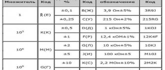
Color ring decoding table
| Color | Number | Decimal multiplier | Accuracy class, % | Temperature coefficient of resistance | % failure |
| Black | 0 | 1*100 | — | — | — |
| Brown | 1 | 1*101 | 1 | 100 | 1 |
| Red | 2 | 1*102 | 2 | 50 | 0,1 |
| Orange | 3 | 1*103 | — | 15 | 0,01 |
| Yellow | 4 | 1*104 | — | 25 | 0,001 |
| Green | 5 | 1*105 | 0,5 | — | — |
| Blue | 6 | 1*106 | 0,25 | 10 | — |
| Violet | 7 | 1*107 | 0,1 | 5 | — |
| Grey | 8 | 1*108 | 0,05 | — | — |
| White | 9 | 1*109 | — | 1 | — |
| Silver | — | 1*10-2 | 10 | — | — |
| Gold | — | 1*10-1 | 5 | — | — |
In a four-band code, the first two stripes indicate two denomination signs, the third strip is the decimal factor, that is, this is the power to which the number denoting the denomination must be raised. The fourth bar indicates the accuracy class of the element. In a five-line cipher, the third line represents the denomination sign, the fourth the decimal factor, and the fifth the accuracy class. If a sixth band is present, it indicates the temperature coefficient. If this ring is one and a half times wider than the others, then it characterizes the percentage of failures.
Convenient online programs will help you decipher the codes of wirewound resistors. Moreover, it makes sense to turn to them when deciphering the SMD resistor code, since there are several marking options that will be very difficult to figure out on your own.
R2 – 80 Ohm (1 W)
From all of the above, we can conclude that the different resistance of the resistors guarantees their different power output, since it is distributed between resistors of different ratings. If you do not take this circumstance into account, you may encounter a lot of difficulties. If one of the resistors is chosen incorrectly, the second one operates under severe temperature conditions. There is also a risk of the resistor catching fire due to non-compliance with power rules.
In order to save time and not have to calculate the power of each individual current resistor, you need to remember one simple rule: the power of the resistor being replaced must be equal to the power of each resistor that makes up the parallel or series circuit. That is, when replacing a 0.5 W resistor, you must ensure that each of the replacement resistors has a power of at least 0.5 W.
When connecting resistors in parallel, it is important to remember that the lower the resistance of the resistor, the greater the current flows through it, which means more power will be dissipated on it
Tags: sconce, view, house, , protective, sign, how, design, , marking, marking resistor, installation, power, multimeter, voltage, nominal, strip, rule, principle, wire, start, , work, size, calculation , reves, resistor, row, light, system, connection, connection resistor, resistance, circuit, ten, type, current, , photo, shield, equivalent, electronic
Types of connection of resistors in an electrical circuit
The effective operation of electrical circuit elements with a resistor depends on the correct choice of not only the resistance itself, but also the method of its connection in the circuit, which can be series, parallel or mixed.
Serial connection
Series connection of resistors
In such a circuit, each subsequent resistor is connected to the previous one, forming an unbranched circuit. The current in series-connected circuits is the same, but the voltage is different. The total resistance of several serially located "rezyuks" is determined very simply - by summing their values.
Formula: Rtot. = R1 + R2 +…+ Rn
The more elements in a series circuit, the greater the total resistance.
Parallel connection
Parallel connection of resistors
In a parallel connection, resistors are connected to each other by inputs and outputs. The voltage across these elements is the same, and the current is distributed between them. The more branches are formed, the more options for current flow and the lower the overall resistance.
Formula: Rtot. = 1/R1 + 1/R2 +…+ 1/Rn
Mixed compound
Mixed connection of resistors
With this method, options for connecting elements are combined. The resistance of each section with a certain type of connection is calculated according to the above rules.
Connecting several resistors in one circuit
If you don’t have the resistance of the required value on hand, you can get it by correctly connecting several resistors. So, if you need a resistance of 100 kOhm, and there are two resistive parts of 50 kOhm each, then you can connect them in series and get the desired result. A resistance of 100 kOhm can be obtained by parallel connection of 200 kOhm elements.
Description of MLT resistors
A fixed resistor is used to ensure the normal operation of electrical circuit components as a current limiter, voltage divider, shunt or load; it is mounted in a wall-mounted manner.
What they look like
A metal film resistor consists of a ceramic tubular base coated with a thin layer of metallized film of a special resistive material. The value of the resistance ratings depends on the composition of the film and the number of turns of the spiral cut on a ceramic base.
Along the edges of the tubular base there are brass caps with silver-plated copper wire leads for installation in the circuit.
To protect against mechanical damage, the current-carrying layer is covered with moisture-resistant organic enamel with markings applied to it.
Most often, the enamel coating is red with alphanumeric or color markings applied to it.
What features do
According to the manufacturing method, MLT resistors can be either with a spiral groove or unthreaded. The most reliable are considered to be non-threaded ones, the ohmic resistance of which is up to 2 kOhm.
During operation, all resistors heat up, dissipating the generated heat. The location of low-power metal-film resistors next to more powerful ones causes intense heating and premature failure of the element - the location of resistive elements at a distance of two diameters between them is considered optimal.
The operational reserve of Soviet resistances is large, but they are subject to aging - during long-term storage in a heated room, the conductive layer oxidizes and crystallizes, and the protective coating hardens.
When and by whom were they produced?
Metal film resistors were produced from 1964 to 1993 - these were the most popular resistors in the USSR, which are still used by many radio amateurs.
Soviet industrial plants producing metal film resistors - Nizhny Novgorod (now NPO ERKON), Kermet in the Penza region.
How to determine by appearance
The circuit diagram shows the required resistor power - everything is clear here. But how can you determine the resistance power by its appearance on the printed circuit board? In general, the larger the case size, the more heat it dissipates. On fairly large resistances, the nominal resistance and its power in watts are indicated.
There is some confusion here, but it's not all that bad. On domestic resistances they put the letter B next to the number. In foreign ones they put W. But these letters are not always there. In imported ones there may be a V or SW before the number. Imported ones may also have the letter B, but domestic MLTs may have nothing or the letter W. A confusing story, of course. But with experience, at least some clarity appears.
How to determine the power of a resistor: it is marked
But there are small resistors on which even the nominal value can hardly fit. In imported ones it is applied with colored stripes. How can you find out their dissipation power?
In the old GOST there was a table of correspondence between sizes and capacities. Domestic resistors are still made in accordance with this table. By the way, there are also imported ones, but they are slightly smaller in size than domestic ones. However, they can also be identified. If you are in doubt about which group a particular specimen belongs to, it is better to assume that it has a lower ability to dissipate heat. There is less chance that the part will burn out soon.
| Resistor type | Diameter, mm | Length, mm | Power dissipation, W |
| Sun | 2,5 | 7,0 | 0,125 |
| ULM, VS | 5,5 | 16,5 | 0,25 |
| Sun | 5,5 | 26,5 | 0,5 |
| 7,6 | 30,5 | 1 | |
| 9,8 | 48,5 | 2 | |
| 25 | 75 | 5 | |
| 30 | 120 | 10 | |
| CMM | 1,8 | 3,8 | 0,05 |
| 2,5 | 8 | 0,125 | |
| MLT | 2 | 6 | 0,125 |
| 3 | 7 | 0,125 | |
| 4,2 | 10,8 | 0,5 | |
| 6,6 | 13 | 1 | |
| 8,6 | 18,5 | 2 |
It seems clear with the sizes of the resistances and their power. Not everything is so simple. There are large resistors with low dissipation capacity and vice versa. But in such cases, this parameter is indicated in the labeling.
Power of SMD resistors
SMD components are designed for surface mounting and have miniature dimensions. The power of SMD resistors is determined by size. It is also in the specifications, but you need to know the series and manufacturer. The power table for SMD resistors contains the most common values.
The dimensions of SMD resistors - this is how you can determine the power of these elements
| Code imperial | Metric code | Length inch/mm | Width inch/mm | Height inch/mm | Power, W |
| 0201 | 0603 | 0,024/0,6 | 0,012/0,3 | 0,01/0,25 | 1/20 (0,05) |
| 0402 | 1005 | 0,04/1,0 | 0,02/0,5 | 0,014/0,35 | 1/16 (0,062) |
| 0603 | 1608 | 0,06/1,55 | 0,03/0,85 | 0,018/0,45 | 1/10 (0,10) |
| 0805 | 2112 | 0,08/2,0 | 0,05/1,2 | 0,018/0,45 | 1/8 (0,125) |
| 1206 | 3216 | 0,12/3,2 | 0,06/1,6 | 0,022/0,55 | 1/4 (0,25) |
| 1210 | 3225 | 0,12/3,2 | 0,10/2,5 | 0,022/0,55 | 1/2 (0,50) |
| 1218 | 3246 | 0,12/3,2 | 0,18/4,6 | 0,022/0,55 | 1,0 |
| 2010 | 5025 | 0,20/2,0 | 0,10/2,5 | 0,024/0,6 | 3/4 (0,75) |
| 2512 | 6332 | 0,25/6,3 | 0,12/3,2 | 0,024/0,6 | 1,0 |
In general, this type of radio elements has no other operational way of determining the current at which they can operate, other than by size. You can recognize them by their characteristics, but finding them is not always easy.
The operating principle of a trimmer resistor
After installing parts of an electronic device, its characteristics usually differ from the nominal ones. To fine-tune the performance of the device, trimming resistors are used. In principle, these are the same variable resistors, but separated into a separate group because they are structurally different from variable resistors. They don't have knobs that you can turn to change. Instead, there are holes for a slotted or straight screwdriver.
Trimmer resistor with cross slot
During operation of the device, after some time, its parameters change. To bring them to the nominal value, trimming resistors are used.
Depending on the type of slider movement, there are trimmer resistors with straight movement and circular movement.
To fine-tune the parameters of an electronic device, trimming resistors with a high number of revolutions are used. In them, the change in resistance from minimum to maximum is carried out in several revolutions or even tens of revolutions of the tuning shaft. In these resistors, the contact movement occurs using a worm gear.
Variable resistor.
A variable resistor is a resistor in which the electrical resistance between the moving contact and the terminals of the resistive element can be changed mechanically.
Variable resistors, also called rheostats or potentiometers, are designed to gradually regulate current and voltage.
The difference is that a rheostat regulates the current in an electrical circuit, and a potentiometer regulates the voltage. On radio circuits, variable resistors are designated by a rectangle with an arrow attached to their body.
In the diagrams, numbers 1 to 3 indicate the location of the resistor outputs.
You can adjust the resistance power of variable resistors by rotating a special knob. Those resistors in which the resistance of the resistor can be adjusted only with a screwdriver or a special hex key are called tuning variable resistors. They look like this:
The principle of operation of a resistor in simple terms
All electronic devices consist of radio components, which are divided into two large types: active and passive.
Active ones amplify electrical signals. A weak signal at the input controls a strong one at the output. In this case, the gain is greater than unity.
The resistor is a passive type of part whose gain is less than unity.
In Soviet times, resistors were called resistances. These days these parts are called resistors. This was done because all parts used in electronics have resistance. To avoid confusion, active resistances are called resistors.
All conductors have resistance, which is considered harmful, since it leads to heating of the element through which the current flows. In addition, electrical power is lost. The value of the resistor is useful. It heats up and produces heat. Heating stoves and lamps used in everyday life operate on this principle.
What is resistor power
Power is defined as the product of current and voltage: P = I * U and is measured in watts (Ohm's law). The power dissipation of a resistor is the maximum current that the resistance can withstand for a long time without compromising performance. That is, this parameter must be selected for each circuit separately - according to the maximum operating current.
How to determine the power of a resistor by appearance: you need to know the correspondence of sizes and powers
The physically dissipated power of a resistor is the amount of heat that its body can “give off” to the environment without overheating to fatal consequences. At the same time, heating should not affect the resistance of the resistor too much.