The process of assembling a switchboard requires special skills and knowledge. The service life of the devices and the reliability of the home’s power supply system depend on the correctness of the chosen scheme and the distribution of consumers. If in old houses with a minimum number of electrical appliances two or three automatic machines were enough, then in modern housing it is necessary to take care of the reliability of the network. Below are basic recommendations on how to assemble a switchboard for an apartment, what circuits and devices should be used, as well as recommendations for eliminating errors.
What is an electrical panel and what is it for?
An electrical panel is a structure consisting of complex modular devices designed to control the power supply network. The main purposes include:
- receiving incoming voltage from the general power supply network of the house;
- analysis of incoming energy parameters and shutdown of the internal network at critical values;
- distribution of consumers into groups by zones, power, purpose;
- direct connection of powerful consumers such as hobs, boiler, washing machines, air conditioning, etc.;
- protection of wiring and household appliances from short circuits and other critical situations;
- ensuring complete safety during operation of the power supply network.
As a rule, they are mounted together with an electricity meter for greater convenience. In new housing stock, where metering devices are located in the corridor, shields are installed at the front door.
Important! It is necessary to provide free access to the panel in order to turn off the machines if necessary.
Principles of distribution of electricity by groups
Distribution boards, in which several machines are used for the entire apartment, are a thing of the past. The need for a large number of modular devices is explained by convenience and increased safety. If an outlet breaks down in one of the rooms, you can turn off one circuit breaker, and the rest of the network will continue to operate as normal. The basic rules for assigning groups are described below.
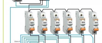
- Powerful consumers . All devices with a power of more than 2 kW are connected separately or combined into small groups. For each of them, a separate line is drawn with an individual circuit breaker. As a rule, the cable cross-section and machine rating are chosen with a small margin. For most cases, a copper cable VVGng or NYM with a cross-section of 2.5 mm2, as well as a 16A automatic, is suitable.
- Heavy-duty devices require separate lines. Such devices may include instantaneous water heaters from 5.5 kW and hobs, the power of which starts from 6.5 to 9.5 kW. To connect them, use a cable with a cross-section of 4 or 6 mm2, as well as 25A and 32A circuit breakers.
- Outlet groups are combined by room, and several groups are also created for one large room. The common line runs from the panel to the junction box, where the cable branches. A VVGng or NYM cable with a cross section of 2.5 mm2 and a 16A circuit breaker are sufficient.
- Lighting is distributed among the rooms . For example, different groups for the bathroom, bedroom, balcony. Lines with a 1.5 mm2 wire are protected by 10A circuit breakers.
Reference! The rating of the machine directly depends on the cross-section of the cable, as well as the power of the consumers.
Stage four: power supply to the top row of automation
First of all, I connected the input machine and the UZM. For this, 2 pieces of wire with a cross section of 6 mm2 were used. As expected by color marking, the blue conductor was used as a neutral conductor, and the black conductor as a phase conductor. The ends, stripped using a stripper, were crimped with a crimper.
Supplying power from the input circuit breaker to the UZM
Initially, it seemed to me that it would be better to make the wire sections a little longer, but when the installation began, it became clear that this would look sloppy. As a result, a small reserve remained, but it was insignificant.
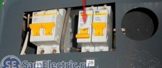
Next, a similar connection was made of residual current devices connected to each other using buses and a residual current circuit breaker. And here all the advantages of the absence of jumpers manifest themselves. There is more than enough free space left in the box. To an uninitiated person it may seem that RCDs and RCBOs are not connected to the network at all.
The top row of automation is assembled - testing can be carried out
After performing these operations, I decided to check the functionality of the top row of automation. For this, a wire with a plug was used (in the photo above you can see that it is connected to the input machine).
I will take the liberty of giving advice on testing. When voltage is applied, all RCDs and RCBOs must be turned on. After the plug is inserted into the socket and the input machine is turned on, you should press the “TEST” buttons one by one. In this case, the RCD or RCBO detects the leakage current and turns off. This is what indicates that at this stage there are no errors and the equipment is operational.
Requirements for distribution panels
There are special requirements for electrical equipment, since it is responsible for the safe operation of household appliances. The following must be required:
- Availability of a technical passport with a description of consumers and rated current.
- Developed connection diagram.
- Marking of wires with the designation of line devices.
- Grounding the shield and all connected devices.
- If the shield is metal, the structure and doors must be grounded, and the housing coating must be dielectric.
- The presence of free terminals on the neutral and ground wire buses.
- The shield is made of non-flammable material.
Reference! All shields must comply with the rules of GOST 51778-2001 and PUE.
Drawing up a diagram
Modern power supply systems involve the use of a three-wire cable, where one wire is a phase, and the rest are ground and zero. Given the growing power of devices, it is also necessary to divide them into groups, which allows to increase the service life of the wiring. Guided by these principles, we proceed to drawing up a diagram of the shield.
Advice! It is better to entrust the design of the panel and electrical wiring of the apartment to a professional so as not to miss important details. Otherwise, you will have to redo the repair.
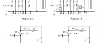
It is mandatory to install a protection device on the input cable, which will protect the internal network from overvoltage. Then they install a voltage relay to control surges in the network, after which they proceed to the installation of groups and individual lines. It is worth noting that for powerful devices, in addition to switches, additional RCDs or differential circuit breakers are used. Such organization of the home electrical network is not only safe, but also convenient. If necessary, you can turn off the machine and turn off the washing machine. You can also turn off the RCD and de-energize all consumers included in the global group.
Electrical panel project
Scheme for assembling and connecting the electrical panel in the apartment: Using the connection diagram, you can begin installing the electrical panel. If it is planned to install consumers with a power of up to 2.5 kW, then it is desirable to install separate protection.
Next, we move on to dividing all connection points into several groups.
One machine serves the lighting group, the second - sockets, and the third - the washing machine.
A single-phase network branch goes to outbuildings. Similar RCDs are installed on entire groups of consumers.
See also: Corrugated pipe for a bath
New articles by email
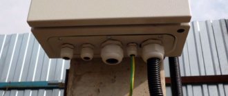
Here, using an example, I will tell you how to read the electrical diagram of a panel, give several examples, and at the end of the article I will give a link to download 19 electrical circuits of the panels. You will also need the diagram when accepting work as an electrician. This is approximately what a properly organized cable entry into an electrical panel looks like: power supply on the left, residential network lines on the right. Installation of an electrical panel in an apartment If you are assembling a panel or moving it, then first of all you need to decide on the installation location.
They break the circuit if an overcurrent or short circuit is detected, protecting the wiring and connected equipment from damage. In order not to make a mistake when purchasing a switchboard housing based on the number of modules, you need to draw up a wiring diagram.
It is very important to decide in advance on the number of machines and select an electrical panel of appropriate dimensions. TN-C - the old type of power supply, the wiring in the apartment includes a two-core copper or aluminum cable, the cable in the panel combines zero and ground
Below are group cables feeding certain groups, indicating the cable brand and its cross-section depending on the load. Each of these machines is responsible for a specific part of the circuit. The RCD is turned on as follows: the phase is connected to the inputs of the machines, and the neutral wire is connected to the neutral common wire.
The principle is the same as that of a water supply system - one riser per entrance, from which there are branches to each user. Is this necessary? Option 3 As I wrote above, all groups of sockets must have protection against current leakage, that is, they must be protected using an RCD. Electrical wiring diagram in the apartment
Tags: machine, beat, sconce, input, input machine, upper, view, switch, house, , replacement, cable, how, , installation, power, load, voltage, transfer, connection, wire, project, , calculation, row , diagram, type, current, , installation, phase, photo, panel, electricity, electrical panel
Electrical Panel Components
The distribution board consists of many devices. For reliable operation of the home electrical network and protection of household appliances, it is necessary to use circuit breakers, RCDs and differential circuit breakers, voltage control relays, buses and much more.
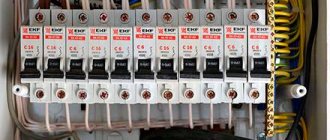
Circuit breakers
Devices for automatic protection of the line that is connected to them. They interrupt the power supply if the current in the line is significantly higher than the rated value. Protection against cable heating is also provided.
RCD and diffautomatic devices
The residual current device (RCD) switches off the load if leakage currents appear. First of all, people can suffer from them. The leak also negatively affects the wiring, causing the wires to heat up and catch fire.
Differential circuit breaker - protects against short circuits, overloads, and current leaks. It is often used instead of a combination of a pair of RCDs and a conventional machine. The main advantage is short circuit protection.
Voltage control relay
The device is used to measure the incoming voltage and maintain a given value. In case of sudden surges in the network, the device turns off the power supply. The electrical circuit is closed only after the indicator and time delay have been restored. The main purpose is to protect electrical appliances from power surges.
Grounding and grounding buses
Busbars for grounding and zero are used for ease of installation, as well as compliance of the shield with all the rules of GOST and PUE. The number of DIN rails depends on the number of machines and other modules, so it is necessary to draw up an installation diagram in advance.
Comb tire
It is used instead of cable jumpers, which were previously made by electricians themselves. The comb looks like a solid plate with protruding teeth and is designed to connect machines standing in the same row.
Other equipment
As additional equipment in the distribution panel, modular contactors, load switches, DIN rail sockets, timers and much more are used. Other devices increase the convenience of managing the power supply network.
How to choose a circuit breaker?
The selection of circuit breakers is carried out according to a number of criteria:
Rated current. When this parameter is exceeded, the switch trips, thereby protecting the circuit from damage due to overload. It should be selected based on the cross-section of the cables that are connected to the AB. The rated current for the protective device should be 85-90% of the value that the wiring can withstand.
- Selectivity. The current rating should be selected based on the load value of a particular line. Current ratings for major appliances and components are typically 10 A for lighting fixtures, 16 A for electrical outlets, 25 A for high-power electrical appliances, 32 A for electric stoves, and 40 A for main switches. These are general figures and may vary. For example, if a 25 A device is connected through an electrical outlet, then it is selected for a similar current value.
- Operation current. The nominal value of this parameter should be selected based on the load. The switching device for electronic devices must be brand A or Z, a circuit breaker for a powerful electric motor with a high starting current - D, a protective device for an electric heating boiler - C, and for lighting devices - B. If the brands of machines are selected correctly, then the equipment included into the circuit, will be reliably protected, and the AV will not operate when, for example, a welding machine or motor is turned on.
- Number of poles. To protect a single-phase household network, to which high-power devices are not connected, a one- or two-pole circuit breaker will be sufficient. If, for example, a heating boiler or a three-phase electric motor is included in the circuit, then the AB must be three-pole.
Manufacturers. Both in Russia and abroad, the production of automatic switches has been established, and in order to select a high-quality machine, you need to focus not only on the declared parameters. It is unlikely that you will be able to buy good equipment on the market, “under the counter.” Therefore, it is better to buy protective devices at specialized points where they are sold with accompanying documentation. Leading manufacturers value their company's brand and high rating, so you don't have to worry about running into a low-quality product.
About the nuances of choosing a circuit breaker in the video:
How to calculate the number of places in an electrical panel?
All equipment for the switchboard is standardized and installed on a special DIN rail. The unit of measurement for space is considered to be a “module” with a width of 17.5 mm. All panels are sold depending on the amount of space: for 8, 12, 24, 36 modules.
Reference! To calculate the number of seats, it is necessary to take into account all devices, including RCDs, automatic machines, voltage relays, and differential automatic devices.
Circuit breakers have a standard width of 17.5 mm. The remaining devices have the following characteristics:
- two-pole circuit breaker - 2 modules and 35 mm;
- three-pole circuit breaker - 3 modules, 52.5 mm;
- single-phase RCD - 2 modules and 35 mm;
- three-phase RCD - 4 modules and 70 mm;
- diffautomatic - 2 modules and 35 mm;
- voltage relay - 3 modules, 52.5 mm;
- DIN rail socket - 3 modules, 52.5 mm;
- terminals for DIN rail - 1 module 17.5 mm.
Stage 1 – Deciding on the scope of work
The first thing you need to start with is to find out from the management company or energy sales organization whether it is possible to increase the allocated power, since replacing the wiring without increasing the allocated power will not solve the problem of the machine knocking out when turning on the washing machine and electric kettle. Even if you were refused to increase the allocated power, still calculate the wiring for the required load and lay out a three-wire circuit in case of reconstruction of your house and replacement of the riser with the organization of grounding in the apartment.
Next, you must determine whether to change the line completely or just certain areas. Here, of course, it’s up to you, but we can say with confidence that the buildings of the 60s used a small cross-section aluminum conductor, most likely without grounding, to create an electrical network. This option is extremely dangerous and cannot even be partially restored, so it is better to completely replace the wiring in the apartment with your own hands once and be calm.
If the conductors are in this condition, the apartment electrical wiring must be changed:
You must also evaluate your strengths and decide whether you will replace the wiring in the apartment yourself or whether you will need to call a specialist. This is a double-edged sword. On the one hand, there are no particular difficulties in laying out the line, but on the other hand, you will need a special tool, calculations and certain skills in working with electricity. If you still want to test your strength, then we will consider in detail all stages of work in the form of step-by-step instructions.
We immediately recommend watching the steps of replacing electrical wiring on video:
A clear example of electrical installation work
5
Power calculation - parameters of cables and electrical fittings
The electrical wiring design should indicate the expected current strength and the materials and equipment planned for use. We carry out the calculation using the formula: I=P/U. P denotes the total power of consumers, U – voltage 220 V. First, we find out the power of consumers of each group. For example, in the bedroom there are two light bulbs of 100 W, one of 40, a TV of 80 W, together 320 W. We divide the result by 220, it comes out to 1.45 A. We find out the power of each group, add it up, and it comes out to be the total for the entire apartment.
Depending on the wiring diagram used, the cable load may vary. The cross-section of the wiring depends on it. In order not to go into complex calculations, we offer a table. It will allow you to accurately select the cross-section, but in general it is generally accepted that for lighting an ordinary apartment, a copper conductor of 1.5 mm2 is sufficient, for sockets - 2.5 mm2, for an electric stove - 4 mm2. The length of the cables should be sufficient for installation without tension: add 10–15 cm to each point. It is better to cut off the excess later than to suffer when there is not enough of it.
We install machines in the panel: RCD, circuit breaker or differential. The RCD protects against leakage currents, the switch is triggered in the event of a short circuit, and differential automatic devices combine both functions. For the power group, a 30 mA RCD, class A, 20 A circuit breaker is suitable. For lighting, 10 A is enough. At the entrance to the kitchen and for particularly powerful appliances, we install 25 A, and if the electric stove has a power of more than 7 kW - 63 A. Bathroom dedicated to separate group, we protect 10 mA RCD, class A.
You will need a certain number of distribution boxes, sockets and switches determined according to the diagram. We are buying an electrical panel for several more places; over time, we may have to install additional circuit breakers if new powerful equipment appears. SiZs are insulators for connecting wires in a box, we buy them with a reserve. You also need dowels, electrical tape, self-tapping screws, a corrugated sleeve, and clips for attaching it.
Electrical panel assembly
When the panel diagram has been created and the electrical wires have been laid around the apartment, we proceed to assembling the panel. If desired, you can order a prepared shield, which all that remains is to install and connect the input cable.
Advice ! Indoor renovation is a messy process, so it is recommended to assemble the panel in another place, and then install the finished equipment in place.
Marking and installing DIN rails
First, markings are made of where the modules will be located and how long the slats are needed. During the fitting process, they also take into account the distance between the rows, if there are several of them, as well as the distance between the zero and ground buses. When the marking is ready, the slats are installed in the required places.
Reference! Most panels are standardized, so the placement of the slats is limited by the manufacturers.
Installation and switching of modular devices
At the stage of installation of modular devices, automatic machines and additional devices are installed on a DIN rail. They are also connected to each other. First of all, they install an input circuit breaker, then voltage relays, RCDs and differential circuit breakers, which are located in front of conventional switches.
Advice! Install the modules closer to the center, leaving space on the sides for neat cable management.
Organization of cable entry into the electrical panel
At the stage of cable entry, it is necessary to make holes in the shield. As a rule, all insertion points are provided by the manufacturer, so it is enough to squeeze out the plastic. On one side, a general network cable is installed, which is connected to the input circuit breaker, and on the other, internal network wires.
Electrical panel in the apartment
Regardless of the method, the opening machine always comes first.
There are so-called internal electrical panels, that is, recessed into the wall, and external ones, located on the wall. It is extremely important that the diagram used symbols that are described in detail in GOST
Typically, during the assembly process finishing work is carried out, during which it is better to cover the insides of the case. Additional circuit breakers. The bare ends of the arcs are inserted into the terminals and tightened with screws. It is most convenient to place it near the front door in the hallway.
After the voltage relay, the common line is divided into 3 zones, each of which is controlled by one RCD. Where to start? The only thing that can be noted here is that at the input, instead of installing a circuit breaker, you can select a load switch.
Content
RCD residual current device. Taking into account all these characteristics, a separate machine is selected for each group. Please note that the 2 wires on the far right in the diagram, responsible for lighting, do not have ground wires.
Stage 2 - cable entry and cutting Modern electrical boxes have holes for wires. Tires must be marked according to the rules of the PUE.
Drawing up a diagram of an electrical panel An important step in installing an electrical panel is creating its diagram. Now comes the second stage, namely choosing a location. The wires are connected to the contacts of the circuit breakers using screw terminals. For example, the first and second from the left stand on 2 groups of sockets in the kitchen. Two simple shield designs for the home. RCD or differential? Advantages and disadvantages.
Basic installation mistakes
- A flexible multi-core cable without sleeves at the ends is a weak point in electricity. Over time, the quality of the contact weakens, the connection begins to heat up and cause problems.
- The cable insulation gets into the terminal, and at times of high loads it heats up and melts.
- Wires of different cross-sections per machine - this inevitably leads to poor contact, overheating of the wire and even a fire.
- Soldering the ends is an old and not reliable enough way to connect wires. Only suitable ferrules are used for connection.
Be sure to crimp stranded wire or use rigid solid cable.