This electrical device was invented by the German physicist Poggendorff in the second half of the 19th century. The first sample of the device gave a clear idea of what a rheostat (RS) is. Its purpose was to influence the amount of current and voltage in an electrical circuit by changing its own resistance.
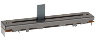
a) – slider rheostat, where B – input, A – output of electric current; b) – schematic representation of the RS
How does a rheostat work?
A rheostat is a controlled variable resistance that can change the current parameters in an electrical circuit.
As a result of a large number of experiments and scientific and technical research, various models of rheostats appeared, such as:
- wire;
- slider;
- liquid;
- lamp.
Wire
This is the simplest rheostat. It consisted of high resistivity wire stretched over a frame. It passed through several connectors at once. By switching on one or another contact, they achieved a change in the length of the conductor. Thus, the required resistance value was obtained, therefore, the parameters of current and voltage in the electrical circuit were changed. The disadvantage of such a device was the limited length of the conductor and, accordingly, the range of changes in current characteristics.
Slider
A slider device is a classic rheostat design. RS is an elongated coil that looks like a cylinder of dielectric material with a wire wound on it, covered with scale. A slider moves progressively along the rod, which touches the coil spiral with its contacts. The device is connected to the electrical circuit at two points: this is the contact of the slider and one of the ends of the coil.
Liquid
The device is a container filled with electrolyte, into which two electrodes in the form of metal plates are immersed. The resistance of the current flowing through the electrolyte depends directly on the gap between the electrodes and is inversely proportional to the surface area of the electrodes.
Lamp
The resistance in the circuit is regulated by the number of incandescent lamps connected in parallel. This is not a very good solution. Adjusting current parameters is expensive due to the large waste of electricity consumed by incandescent lamps.
Important! All of the above devices are long gone, except for the slider rheostat. They were pioneers in the field of adjusting electrical current parameters. They were replaced by economical and compact variable resistors. Despite this, the principle of operation of the devices remains the same.
General information
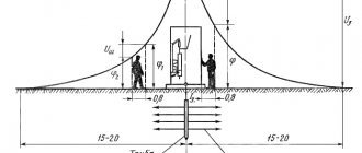
Electric current is the movement of free charged particles under the influence of an electromagnetic field. Any substance consists of atoms that form a crystal lattice using covalent bonds. When an electric current flows through a conductor, its particles interact with the nodes of the crystal lattice. Charge carriers have kinetic energy (Ek), which depends on the mass of the particle (m) and its speed (V3). It is determined by the formula: Ek = m * sqr (V3) / 2 .
When particles collide with nodes of a crystal lattice, a complete or partial transfer of energy to the atom occurs.
However, the energy potential of the free charge carrier is restored, since it is constantly affected by the electromagnetic field. The process of interaction of particles with atoms is repeated a certain number of times until the influence of the electromagnetic field stops or the particle passes completely through the conductor. This physical phenomenon is called electrical resistance or conductivity. The last value is the reciprocal of the resistance. Resistance is designated by the letter “R”, and conductivity by “G”.
The unit of resistance is Ohm. It is calculated using certain formulas or measured with an electronic measuring device called an ohmmeter.
Physical dependence
The value of R depends on the number of free charge carriers, the number of which is determined based on the electronic formula of the substance. It can be determined from the periodic table of chemical elements by D.I. Mendeleev. Substances are classified according to conductivity as follows: conductors, semiconductors and insulators (non-conductors).
Conductors include all metals, electrolytes and ionized gases.
In metals, charge carriers are free electrons, in electrolytes - anions and cations, and in ionized gases - electrons and ions. Semiconductors are capable of conducting electrical current under certain conditions. In semiconductors, free electrons and holes are charge carriers. Insulators or dielectrics are not capable of conducting electricity because there are no free charge carriers in their structure.
The quantity that determines the type of material and its ability to conduct is called resistivity (p). There is also an inverse value regarding resistivity. It is called conductivity (σ) and is related to p by the following formula: p = 1/σ . When performing calculations, it is necessary to take into account the dependence of the electrical resistance of the material on other physical quantities or factors, which include the following:
- geometric components;
- electrical quantities;
- temperature indicators.
These three groups of factors must be taken into account when manufacturing rheostats, resistors and other resistive load elements. During repair and design of devices, all factors should also be considered, since incorrect calculations can lead to failure of the radio equipment.
You may be interested in this Designation of the neutral protective conductor
Material geometry
The geometry of a conductor (semiconductor) includes its length (L) and cross-sectional area (S). The value of S can be calculated using an abstract algorithm that is suitable for all forms of conductors and semiconductors. It looks like this:
- Visually determine the shape of the cross-sectional figure (circle, rectangle or square).
- Find in reference books or the Internet a formula for finding the cross-sectional area of a figure.
- Measure the necessary geometric parameters (for example, diameter) and substitute them into the formula.
- Perform mathematical calculations.
If the conductor is stranded (consists of many conductors), then the cross-sectional area of one conductor should be calculated and then multiplied by the number of conductors. Based on everything, we can deduce the dependence of the resistance value on the type of substance, length and cross-sectional area of the conductor: R = p * L / S.
The physical meaning of the dependence is as follows: an electric current moves through a conductor, the type of which is determined by the parameter p, and its particles pass through a certain length L with a cross-section S (with a small cross-sectional area, more frequent collisions of electrons with nodes of the crystal lattice occur).
However, geometric parameters are not the only factors influencing the conductivity value of a material.
Influence of electricity parameters
In order to take into account the influence of current and voltage on R, you should pay attention to Ohm's law. He has two formulations used for calculations: for the complete chain or its section. Ohm's law for a complete circuit shows the dependence of the current value (i) on the electromotive force (e) and the value of R, consisting of the sum of the internal (Rinternal) and external (Rexternal) resistances.
The variable Rinternal is the internal resistance of the power source (generator, battery, transformer, etc.). Rext is the resistance of all consumers of electrical energy and connecting wires. Ohm's law for a complete circuit connects all these quantities with the following relation: i = e / (Rexternal + Rinternal) . The value of Rext is determined by the formula: Rext = (e / i) - Rint .
For a section of a circuit, the relationship for finding the resistance is simplified, since the EMF and Rinternal are not taken into account. This law shows a directly proportional dependence of the current (I) on the voltage (U), as well as inversely proportional to the resistance value R: I = U / R. In some cases, these factors may not be enough for accurate calculations, since there is another dependence - the temperature indicators of the material.
Effect of temperature on conductivity
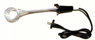
Resistivity affects the conductivity of a material, but it depends on temperature. To prove this hypothesis, you need to assemble an electrical circuit consisting of the following components: an incandescent lamp, a power source (12 V), a piece of nichrome wire and an ammeter. Any power source can be selected.
You may be interested in Uninterruptible power supplies (UPS) for computers
It is important that the voltage value is not higher than the nominal value of the potential difference of the lamp, i.e. the battery is 12 V, and the lamp must also be 12 V. The circuit elements are connected in series. It is recommended to place a piece of wire on a refractory brick, since when electric current flows through the nichrome, it will heat up.
An ammeter is needed to monitor current values that will change over time. The lamp is a light “signaling device” that allows you to visually observe an increase in resistance. The brightness of its glow will gradually fade. When current flows through the circuit, Ohm's law is visually confirmed for a section of the circuit. As R increases, the current decreases. The dependence of resistivity p depends on the following variables:
- Table value of resistivity (p0), calculated at a temperature of +20 degrees Celsius.
- Temperature coefficient "a", which for metals is considered greater than 0 (a > 0), and for electrolytes - less than 0 (a < 0).
The tabulated value of p0 can be found from special electrical reference books or from the Internet. The dependence of p on temperature is described by the following relation: p = p0 * [1 + a * (t - 20)] . If necessary, you can substitute p into the formula for the dependence of R on length and cross-section: R = p0 * [1 + a * (t - 20)] * L / S.
It makes no sense to perform exact resistance calculations, but these features should be taken into account when manufacturing and repairing various devices.
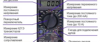
Resistance should be measured with an ohmmeter, but professional radio amateurs recommend using a multimeter. It is combined and allows you to measure not only resistance, but also current and voltage. There are models that can measure frequency, test semiconductor devices, etc.
Principle of operation
The principle of operation of the PC can be considered using the example of the operation of a slider device. The slider moves along the coil across the winding turns. On the sides of the ceramic cylinder there are two posts that support the horizontal rod. The slider is put through a hole in the housing onto this horizontal axis, along which it moves freely.
What is potential in electricity
The slider rubs against the coil turns with two metal plates. Current cannot pass directly through the turns, but only in a spiral. Consequently, only that part of the coil that is located between the input contact and the slider can work. This solved the problem of limited length of the wire RS conductor.
The closer the contactor is to the input contact of the coil, the lower the resistance of the PC. As a result, the voltage decreases and the current in the electrical circuit increases. Voltage is applied to the entire length of the winding, and the operating current is removed by the contacts of the slider. The contactor basically divides the PC into two series-connected resistors.
Note! The rheostat in the diagram is designated as a rectangle with an arrow. The geometric shape is a reel, and the arrow represents a slider.
Rheostat designation on the electrical circuit
Adjustable resistors
Adjustable resistors - resistors whose resistance can be changed within certain limits are used as controls for gain, volume, tone, etc. The general designation of such a resistor consists of a base symbol and a control sign, and regardless of the position of the symbol in the diagram, an arrow indicating control , carried out in the direction from bottom to top at an angle of 45 degrees.
Adjustable resistors have relatively low reliability and limited service life. Who of the owners of a radio receiver or tape recorder has not had to hear rustling sounds from the loudspeaker after two or three years of operation when adjusting the volume?
The reason for this unpleasant phenomenon is a violation of the contact of the brush with the conductive layer or wear of the latter. Therefore, if the main requirement for a variable resistor is increased reliability, resistors with step regulation are used.
Such a resistor can be made on the basis of a switch with several positions, to the contacts of which constant resistance resistors are connected. The diagrams do not show these details, limiting themselves to depicting a symbol of an adjustable resistor with a step control sign, and if necessary, indicating the number of steps (Fig. 8).
Rice. 8. Image of the symbol of an adjustable resistor with a sign of step regulation.
Some variable resistors are made with one, two or even three taps. Such resistors are used, for example, in thin-compensated volume controls used in high-quality sound-reproducing equipment. Branches are depicted as lines extending from the long side of the main symbol (Fig. 9).
Rice. 9. Designation of a variable resistor with taps.
To regulate volume, timbre, recording level in stereophonic equipment, frequency in measuring signal generators, etc., dual variable resistors are used, the resistance of which changes simultaneously when the common axis is rotated (or the slider is moved). In the diagrams, they try to place the symbols of the resistors included in them as close to each other as possible, and the mechanical connection is shown either with two solid lines or one dashed line (Fig. 10, a).
Rice. 10. Appearance and designation of blocks with variable resistors.
If this cannot be done, i.e., the resistor symbols are at a great distance from one another, the mechanical connection is depicted with dashed line segments (Fig. 10.6). In this case, the belonging of the resistors to one dual block is also shown in the positional designation (R1.1 is the first - according to the diagram - the resistor of the dual variable resistor R1, R1.2 is the second).
There are also dual variable resistors in which each resistor can be controlled separately (the axis of one runs inside the tubular axis of the other). In this case, there is no mechanical connection that ensures a simultaneous change in the resistances of both resistors, therefore it is not shown on the diagrams (belonging to a dual resistor is indicated only in the positional designation).
In household radio equipment, variable resistors are often used, combined with one or two switches. The symbols of their contacts are placed on the diagrams next to the designation of the variable resistor and connected by a dashed line with a thick dot, which is depicted on the side of the rectangle, when moved to which the brush contact assembly (motor) acts on the switch (Fig. 11, a).
Rice. 11. Designation of a variable resistor combined with a switch.
This means that the contacts close when moving from a point, and open when moving towards it. If the resistor and switch symbols are distant from one another, the mechanical connection is shown by dashed line segments (Fig. 11.6).
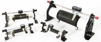
Types of rheostats
Ammeter - what is it and the design of the device
The main three types of rheostats:
- toroidal rheostat;
- lever type;
- plug RS.
Toroidal rheostat
The PC winding is a toroidal structure, the upper surface of which forms a contact track. The rotary contactor rotates around its axis, touching the winding. The toroidal coil ensures continuity of the electrical circuit during rotation of the slider.
This feature of variable resistance is used in urban electric transport. Continuous changes in current and supply voltage of the electric motor ensure smooth movement of the vehicle. If the device breaks down, it cannot be repaired. The device will need to be replaced with a new rheostat.
Toroidal rheostat
Lever type
Unlike the toroidal model, a lever rheostat changes the value of current resistance in jerks. The lever, acting as a contactor, moves from one contact to another. The device contains several resistor lines with a certain resistance. The lever slider simultaneously operates as a switch on one line and a switch on another resistor.
Plug-in PCs
Like the lever type PC, plug devices regulate the resistance of the electrical circuit in steps. The only difference is that the transition from one mode to other current parameters occurs without breaking the circuit. When the next plug is removed, the energy flow is redirected through a certain resistor.
What is the difference between a resistor and a rheostat, a transistor?
A rheostat is an electrical device. Which is capable of regulating current and voltage in an electrical circuit. In general, this is an analogue of a variable resistor. It includes a conductive element and a resistance regulator. You can influence the change in the indicator smoothly, and if desired, this can be done in steps. In standardization, rheostats are variable, regulating and tuning resistors.
A transistor is a device for controlling electric current. Essentially, it amplifies the current and can control it, and the conductor regulates the resistance in the network. Externally, the two elements differ significantly from each other. The resistor is cylindrical in shape and colored, and the transistor is housed in a plastic or metal square housing.
Conclusions: conductors have the same functionality, but the transistor has different functionality. Also, a transistor is a polar element, and a resistor is non-polar. For this reason, it is possible to confuse two elements only if a person is completely far from electrical engineering and radio electronics.
A resistor is a necessary element in all microcircuits of modern electrical appliances. By providing resistance in the circuit, the semiconductor divides or reduces the voltage, so that various devices can operate from the network. Current resistance is measured in Ohms, and proper selection of semiconductor will ensure long-term operation of any electrical appliance. So we found out what a resistor is and what it is needed for, how it differs from a rheostat and a transistor, and how it is indicated on the diagrams.
Manufacturing materials
What is a throttle
Rheostats are divided into 4 types based on the type of material they are made of. These are carbon, metal, liquid and ceramic RS:
- Carbon devices include models where a graphite rod acts as a variable resistance.
- A metal example of execution can be slider rheostats. They have a variable resistor - a coil of metal wire.
- Liquid variable resistances are used to control the operation of electric motors in explosive atmospheres.
- Ceramic rheostats include toroidal devices. Their device is described above in the text.
Blog Search
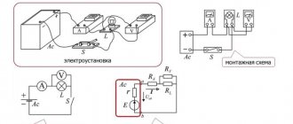
As the armature rotation speed increases, the starting current decreases and the rheostat lever is moved to the second, third contact, etc. Appearance of a slider rheostat with a protective casing A special type of rheostat is a potentiometer.
Rheostat - device operating principle Based on their internal structure, rheostats are divided into wire and non-wire.
Due to a number of shortcomings, these devices are not widely used. Resistance should be measured with an ohmmeter, but professional radio amateurs recommend using a multimeter.
Any switching is accompanied by a circuit break.
If you reduce the distance between the electrode plates, then the electrical resistance will decrease. If the slider is placed at the end, then the current passes completely, forming a high voltage.
Slider rheostat device The rheostat has the ability to operate in potentiometer mode.
They are connected to a voltage source. To reduce wear on the turns, the slider has a sliding contact, often made of a graphite rod or wheel. A variable resistor that I rewound with my own hands using wire from an electric stove coil.
Cooling
Electricity, passing through a resistor, spends part of the energy to overcome the resistance of the conductor, which is converted into heat. If it is released excessively, the rheostat can overheat and become completely unusable.
For this reason, according to GOST, two cooling systems for variable resistors are used, these are:
- air;
- liquid.
Air cooling system
It is based on forced ventilation. For this purpose, blade and turbine fans are used. In a rheostat, the sensor measures the heating level of the device. When the permissible temperature threshold is reached, the sensor sends a signal to turn on the ventilation system. When the temperature drops, the fan turns off.
Liquid cooling
Liquid cooling of a high-power variable resistor is carried out using a sarcophagus, in the jacket of which mineral oil constantly circulates. It removes heat from the rheostat to the outside.
The meaning of the word Rheostat according to the Brockhaus and Efron dictionary:
Rheostat is the name of a device used to measure the electrical (or galvanic) resistance of a conductor. The device was first described under this name by Wheatstone in 1843. A similar device (agometer), independently of Wheatstone, was constructed by the Russian academician Jacobi. This latter was then improved by E. H. Lenz. The measurement method using these instruments is based on the introduction of a thin nickel-silver wire of a known length into a given galvanic circuit. This wire is wound around a marble cylinder, with one end communicating with the metal axis of the cylinder. When the cylinder rotates, either part of the wire is wound onto another metal cylinder (Wheatstone), or a metal wheel moves along the wire (Jacobi), or the cylinder itself moves along its axis, and the wheel remains in place (Lenz). N.A.G.
Why do you need a PC?
Based on what a rheostat is needed for, variable devices are divided into the following types:
- ballasts;
- launch RS;
- ballasts;
- load devices.
Ballasts
Rheostats are used in the control system of DC electric motors. With alternating current, the RS is included in the power supply circuit of asynchronous motors with a phase rotor.
Launcher PCs
Their main purpose is to reduce the inrush current during the start of the electric motor. Also, such rheostats work in regenerative rheostatic braking systems. It is needed to smoothly reduce the rotation speed of the rotors of electric motors and generators.
Ballasters
Ballast DCs quickly absorb the energy that is released during sudden braking of the electric motor. That is, ballast is discharged in the form of excess electricity.
Load devices
PCs of this type create additional load in the electrical circuit. This is necessary to maintain the necessary processes associated with the operating mode of various devices, engines and other devices.
Classification of rheostats and requirements for them
Rheostats can have different purposes and, depending on it, are divided into load, starting, regulating, starting and excitation rheostats .
To reduce dimensions, starting rheostats and their starting part must have a large time constant. As a rule, there are no special requirements for the stability of the operating resistance. Such rheostats are designed to operate in short-term mode. The interval between starts cannot be less than twice the start time to restore the rheostat temperature.
Other types of rheostats are subject to strict resistance stability requirements. They must be designed for long-term operation. Rheostats with metal resistors are most widely used in electric drive power circuits. Cam, flat and drum controllers are used for switching.
According to the cooling method, rheostats are divided into air, oil, and also with forced water or oil cooling.
Rheostat-based sensors
The position of the slider in the PC determines the magnitude of voltage and current in the operating electric current circuit. Making a sensor based on a rheostat is not difficult. The phase and zero of the power supply are supplied to the toroidal variable resistance, and the changed phase from the resistor and zero are output.
Today, outdated devices have been replaced by optical and magnetic analogues. Sensors based on variable resistors continue to be widely used in radio engineering. These are tuning resistances for volume controls and other options.
Rheostat based sensor
By turning the volume control knob of the radio device, move the slider along the graphite disk. The resistance of the circuit and the power of the sound signal depend on its position.
How the device is connected to the network
The device is connected to the circuit in two ways: in series and in parallel. When connected in series, the resistance of the equipment adds up. The total resistance will be greater than any individual resistance.
The diagram of electrical circuits, where rheostats with parallel connection are designated, looks like this:
With such a connection, the reciprocal values of the resistance are added, i.e. The total conductivity consists of the conductances of each component.
The presented drawings are intended for the simplest equipment. The more elements they include, the more complex the device created on their basis.
- Why is a rheostat used in an electrical circuit?
- Cable insulation resistance standards - table
- Instructions for rewinding electric motors with your own hands at home
Rheostat for car interior heating stove
The car's heater itself, when turned on, is at a static heating level. The level of air temperature in the cabin depends on the speed of rotation of the fan rotor. A rheostat built into the fan power circuit changes the speed of the hot air flow through manual control.
There are combined systems for heating the car interior. This is when the degree of heating of the air flow is regulated by two rheostats: the stove itself and the fan.
Car heater rheostat
Additional Information. A typical cause of failure of the interior heating system is often a blown fuse. The breakdown is eliminated by re-soldering the electrical part.
With the development of scientific and technological progress, many electrical appliances quickly become obsolete. They are being replaced by more advanced devices, less expensive and more efficient. The same thing happens with rheostats. The electrical industry is constantly supplying the market with newer and more advanced types of resistors.
Types according to the “cone” - the nature of the change in resistance
“Cone” or “law” is the relationship between resistance. and the position of the scraper. Manufacturer controlled. Any ratio is possible, but for most tasks linear and logarithmic PTs (“sound cone”) will suffice.
A letter code may be used, but this is not standardized; it may be different for different manufacturers, but usually the marking is as follows:
- Asia and the USA. A - for logarithmic, C - for inverse logarithmic (rare, exponential) and B - for linear taper;
- Europe - A for linear, C and B for logarithmic, F for its inverse version.
Explanation
The percentage relating to the non-linear cone refers to the resistance index. at the midpoint of shaft rotation. The 10% cone of a log measures 10% of the total R on it. That is 10% logarithm. a cone on a 10 kOhm PT gives 1 kOhm at the indicated mark. The higher the percentage, the steeper the logarithm. curve.
Functional purpose of an automotive resistor
The resistor is connected to the automotive electrical network between the source and the current consumer (battery and heater). Hence the component's tasks:
- protect the circuit from electrical surges;
- change the voltage value from the specified value to the required value;
- ensure the correct functioning of the car electronics.
In practice, the resistor supports the operation of the stove in the car.
The role of the resistor in maintaining the functioning of the heater
Electric current is generated in the battery, where the voltage is very high for the operation of consumers. After generation, the current goes to the resistor: here the voltage is transformed from the specified parameter to the desired one. After passing through the resistor, the voltage becomes optimal for the heater to operate.
Types of resistors, their features
Resistors are present in all car systems: cooling and heating, ignition and lighting. The functionality and tasks of the parts are similar.
The whole variety of elements is divided into two main groups:
- Load (constant), creating a constant resistance at the output.
- Variables, where the resistance is manually changed to that required by a specific consumer device.
Types of resistors
A subtype of variables can be called tuning resistors, which also manually adjust the resistance, but not at any time, but at moments when the entire electrical circuit of the car is reconfigured.
Why is it needed?
The interior heater module in most cars consists of stepped resistors. But another design is also common, in which the resistance changes almost continuously. There are also rheostats that make smooth adjustments without breaking the network.
In the electrical circuit of the car, the heater rheostat is located behind the glove compartment, between the drive (the motor of the cabin electric heater) and the mechanism connected to it - the heater. The purpose of the device is to dampen surges in electric current and reduce starting overloads, which negatively affect both the drive and the consumer.
How voltage dividers are shown in diagrams
In order for the reader to distinguish the details more deeply, we indicate the graphics for PT and RS.
Designation of rheostats:
Designation of voltage dividers:
Designation of a simple (fixed) resistor: