Barium titanate (BaTiO3) is a ferroelectric substance first defined (identified) by scientists in 1944. The resistivity of barium titanate at room temperature becomes an n-type controlled valence semiconductor with a resistance of 1 -106 Ohm * cm. But for this, barium titanate must be supplemented with a small amount of rare earth elements. Scientists first produced something similar in 1951. And after another ten years (in 1961), the existing base of radio components was supplemented by a posistor - an electronic component launched into mass production.
Element properties
It is worth studying what a posistor is, how to check it in a circuit - it will become clear later. This element is capable of changing properties depending on temperature. Its physical value resistance is measured. At room temperature, the ohmmeter readings show units or tens of ohms.
When heated in operation, the resistance begins to change upward. The ohmmeter values already show hundreds of kilo-ohms, which indicates the normal state of the element - such a posistor is working. How to check if there is a suspicion of a faulty circuit? Below are ways to resolve this issue.
Due to their properties, posistors are widely used in microelectronics for various purposes:
- Protection of power circuits. With increased current consumption, the element heats up and increases the resistance to a maximum when a current cutoff is observed.
- In heating circuits. Thanks to posistors, an automatic heating control system is implemented.
- In thermal sensor circuits.
How to test a variable resistor?
The principle of operation in this case is not very different; we will describe them using the example of the part shown in Figure 7.
Rice. 7. Trimmer resistor (internal circuit marked with red circle)
The algorithm is as follows:
- We take a measurement between legs “1” and “3” (see Fig. 7) and compare the resulting value with the nominal value.
- We connect the probes to terminals “2” and any of the remaining ones (“1” or “3”, it doesn’t matter).
- We rotate the adjustment knob and observe the readings of the device; they should change in the range from 0 to the value obtained in step 1.
Internal structure of the element
A resistor changes its resistance with heating, just like a posistor. How to check the first element? This one is simple. The resistor values fluctuate within insignificant limits. A posistor is capable of completely blocking the current passing through it, just like a themistor. Only the latter exhibits an inverse dependence on temperature.
To know how to check the serviceability of a posistor, you should determine its main operating characteristics. These include:
- nominal resistance at normal ambient temperature (usually 20-25 degrees);
- The switching resistance is determined at the point of the resistance versus temperature characteristic when the first parameter increases by 2 times compared to the nominal value;
- the maximum voltage that the element can withstand without failure;
- current load values: rated, switching, maximum possible and stalling; For testing, these parameters are important only if the posistor will be used in high-precision circuits.
Application in analog technology
Over time, the varistor parameters change. Its response threshold may shift, which will lead to failure of the entire device.
To check the actual threshold voltage, in addition to a multimeter, you will need an LATR or a rheostat connected according to a potentiometer circuit, a fuse in a glass or ceramic case of 0.5-1 Ampere.
To do this, a circuit is assembled in which an electric potential exceeding the varistor response voltage is supplied to the rheostat. One terminal of the varistor is connected to the middle moving contact of the rheostat, and a fuse is connected to the second. The other contact of the fuse is connected to one of the extreme contacts of the rheostat.
The multimeter is connected in parallel to the varistor and switched to voltmeter mode. The switch selects a scale that covers the value of the input voltage of the assembled circuit.
Then, using the moving contact of the rheostat, the voltage smoothly changes from zero until the varistor operates. This is determined by a voltmeter. At first, the multimeter readings will increase, and then reset to zero.
The last maximum non-zero value will be the threshold voltage.
The fuse is there to protect the varistor. With a long-term passage of a current of 1 Ampere, a varistor can even explode from overheating, although in a short pulse it can withstand currents of thousands of amperes.
Everything is repeated after changing the poles of the supply voltage and replacing the fuse. If the multimeter readings are within the limits required for normal operation of the circuit, then the varistor is operational, otherwise it needs to be replaced. When using alternating current, reversing the polarity of the contacts is not required.
If a varistor in a circuit is used as an analog computer, then do not limit yourself to just measuring resistance by transferring test leads from one contact to another.
The use of a varistor in an analog computer for exponentiation, root extraction and other mathematical operations requires a certain accuracy in setting the parameters. In this case, it will be necessary to construct a current-voltage characteristic to verify the correctness of the calculations.
As in the previous case, you will need a rheostat, a fuse and two multimeters. First, according to the first scheme, the varistor is checked for serviceability.
Then the second multimeter is connected in series to the varistor in milliammeter mode. Now, using a rheostat, the voltage on the varistor changes from 0 to a value that does not reach the threshold.
Multimeter readings are recorded with such a voltage change step that it is possible to draw a high-quality current-voltage characteristic from them. Depending on the resulting parabola, other nonlinear elements will be added to correct it or the varistor will be replaced.
Element in the demagnetization circuit
How to check a posistor on a TV? The answer to the question follows from the principle of its operation. The malfunction of the element is manifested by distortion of the image due to magnetization. To eliminate this defect, the screen design uses a grid connected in series with a posistor. This design is called an external loop, covering the entire surface of the screen from the inside.
The posistor is often soldered into the screen mask circuit, making it difficult to test on site. Before taking measurements, you should unsolder at least one end from the grid. The best option would be to completely remove it from the circuit.
To heat the element, use a regular or hair dryer. To check without external heating, you will need to assemble an electrical circuit and determine the type of posistor by the markings. Based on the device’s passport data, the element’s operating current and the corresponding temperature are determined.
The serviceability of the posistor can be conditionally determined by heating it with a hairdryer. If the resistance increases, then the element is good. However, with this verification option, there remains the possibility of an erroneous result. After all, the resistance of circuit elements changes over the years, which leads to instability of the assembly.
Functional check
When devices malfunction, the state of the power circuits is first determined, and the task arises of how to check the varistor. First, an external examination is done.
Check for carbon deposits, blackening or mechanical damage. If any of this is present, the varistor needs to be replaced. Otherwise, unsolder at least one pin.
Without soldering the contacts, it will not be possible to measure the resistance of the varistor, since it is connected in parallel to the entire circuit of the device or some of its modules. Therefore, instead of determining the resistance of the varistor, at best, the total resistance of the entire device will be measured.
To desolder the lead, you need a soldering iron, desoldering pump, and pliers. The area around the terminal is heated with a soldering iron. The molten solder is pumped out using a desoldering pump. Use pliers to remove the varistor lead from the board.
Then a direct test of the varistor begins with a multimeter or ohmmeter. The operating mode switch is set to the “resistance measurement” position. The largest measurement scale (200 MΩ) is selected.
The probes are connected to the varistor terminals. Resistance is measured. Then the probes are swapped and the second value of the measured resistance is recorded.
The multimeter should show values in the tens of megohms. If in at least one measurement the multimeter shows values other than MOhm, it means that the varistor is faulty and needs to be replaced.
Some devices have a fuse in series with the varistor. Then just take it out and we get a version with one free contact. There is no need to solder anything.
Next, you should use a multimeter, and how the varistor is checked and measurements are taken was described above.
Why do we need a picture tube system?
On TV screens without a demagnetization system, the image would be distorted with a slight influence of the electromagnetic field. It is emitted by all household appliances, the surface of the Earth is penetrated by invisible waves.
Thus, amplifiers, large speakers, and heating elements are often located next to televisions. Without a screen mask, the image would be constantly distorted. During initial operation, a small current flows through the posistor, which does not cause it to heat up. In this case, the mask physically experiences tension from the emerging field.
This applied magnetic field demagnetizes the mask when the TV is turned on. Often this process is accompanied by a sound comparable to hitting a gong. The larger the screen diagonal, the higher the sound pitch. The posistor at this moment passes a high amplitude current through itself, which leads to its heating. The resistance increases and the element closes the circuit.
How to fix it yourself
Finding the device is not difficult; it is located behind the back cover, next to the plug, which includes a demagnetization loop.
If the reason is magnetization of the device, it must be demagnetized. To do this, the device is unsoldered from the TV and connected to a demagnetization system.
But in most cases, damage to the device requires its replacement. You need to unsolder the old one and solder in a new one with similar characteristics. If we select the wrong device, it will not work.
Source
Options for faults in picture tubes
If, when you first turn it on, the image is distorted or ripples and stripes are observed, then the posistor is most likely to blame. How to check an element in a circuit with a multimeter? It is easier to do this on a cold circuit, because the resistance of the posistor is minimal.
Often the soldered contacts simply fall off due to prolonged use. A posistor refers to circuit elements that constantly operate in a heated state. Using an ohmmeter, check the connection of the screen mask with the output of the second leg of the posistor. If it is minimal, this indicates a reliable connection. Perhaps the element does not trigger the cutoff.
If the posistor is faulty and short-circuited, then the power supply fuse blows when turned on for the first time. Provided that this occurs without a visible short circuit in the circuit, you can check the malfunction by completely disconnecting the screen mask and the posistor.
Types of markings
On components produced during the Soviet Union, it was customary to indicate the denomination on the body of the part (see Fig. 1). This option did not require decoding, but if the integrity of the structure was damaged or the paint burned out, problems with text recognition could arise. In such cases, you could always turn to the circuit diagram that supplied all household appliances.
Figure 1. “ULI” resistor, the part rating and tolerance are visible on the body
Surface-mounted components (for example, SMD resistor, diode, capacitor, etc.) began to be marked with numbers, but due to the small size of the parts, this information needed to be encrypted. For resistances, in most cases, a designation of three numbers is accepted, where the first two are the value, and the last is the multiplier (see Fig. 3).
Rice. 3. An example of decoding the value of an SMD resistor
Element in the cooler circuit
If the back of the refrigerator - the radiator - does not heat up, then for self-repair you need to familiarize yourself with how to check the posistor. Two types of starters can be used in the refrigerator: with posistors and with electromagnetic relays. The former spend part of the energy on heat loss in the resistance of the element, the latter are less reliable, but do not heat up.
Most posistors in refrigerators should have a resistance of about 20–30 ohms. When heated, there may be several kiloohms. If the values significantly exceed those given, the element must be replaced. It is important to let the posistor cool to room temperature before taking measurements.
Checking for a break
Actions are performed in the following order:
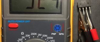
- We turn on the device in the “dialing” mode. In Figure 5 this position is marked as “1”.
Rice. 5. Setting the mode (1) and connecting probes (2 and 3) - We connect the probes to sockets “2” and “3” (see Fig. 5). Despite the fact that in our testing polarity does not matter, it is better to immediately train yourself to connect the probes correctly. Therefore, we connect the red wire () to socket “2”, and the black wire (-) to “3”.
If the model of the device you are using differs from the one shown in the figure, read the instructions that came with the multimeter.
- We touch the pins of the problematic element on the board with the probes. If the part “does not ring” (the multimeter will show the number 1, that is, an infinitely large resistance), we can state that the test showed a break in the resistor.
Please note that this testing can be carried out without desoldering the element from the board, but this does not guarantee a 100% result, since the tester can show communication through other components of the circuit.
PTC fault
Among modern color picture tube TVs, a faulty posistor in the picture tube demagnetization circuit is quite common.
Externally, a posistor malfunction can manifest itself as follows:
The TV does not turn on, the protective fuse burns out.
On the color screen of a CRT TV, areas of unnatural color rendering appear, simply colored spots.
As a rule, distorted color reproduction is noticeable in the corners of the screen. Rainbow spots in the corners of the screen do not appear immediately, but gradually, over time.
Such a malfunction sometimes misleads people, which leads to the misconception that the TV picture tube is faulty. In fact, the kinescope is completely intact, just highly magnetized.
Magnetization of the kinescope may appear if the TV has not been disconnected from the power supply for a long time, i.e. The device was working for a long time or was in standby mode. As a result, under the influence of the Earth’s magnetic field, a special plate was magnetized inside the kinescope; it is called a shadow mask.
Thanks to this mask, three electron beams are projected onto the phosphor layer of the screen: red, blue and green. Naturally, if it is magnetized, then this introduces distortion and the rays are brought together incorrectly. Because of this, areas of unnatural color rendition appear on the screen.
How does the degaussing circuit work in CRT TVs?
In practice, two demagnetization schemes are used. One uses a two-terminal posistor, and the other uses a three-terminal one. The difference is small, but it is there. Let's look at both schemes.
If you don’t know what a posistor is, then read the page about thermistors and their varieties.
In color picture tube TVs with small screen diagonals (21 inches or less), the picture tube demagnetization circuit is implemented according to a fairly simple scheme. Take a look.
The circuit consists of a posistor (PTC) and an inductor (“loop”). It is designated as L1. Coil L1 is a kind of electromagnet. Thanks to it, magnetization is removed from the kinescope mask.
Every time you turn on the TV, a fairly significant current begins to flow through the coil, with an amplitude of about 10 amperes and a mains frequency (50 Hz). This current in the coil generates an electromagnetic field. It demagnetizes the kinescope mask. In order for the electromagnetic field to fade smoothly and quickly, a posistor (PTC) is installed in series with the coil. Let me remind you that at room temperature, in the so-called “cold” state, its resistance is small and equal to only 18
Under the influence of a large surge of current, it instantly heats up and its resistance increases sharply. As a result, the current in the coil (“loop”) decreases, and, consequently, the electromagnetic field that was required to demagnetize the kinescope. That's all, the kinescope is demagnetized.
Further, while the TV is working or simply “resting” in standby mode, the posistor in the demagnetization circuit is in a “heated” state and limits the current in the demagnetization coil L1 to a minimum. This continues until the TV is disconnected from the 220V network and the posistor cools down. The next time you turn on the TV, it will work again together with the demagnetization loop.
This demagnetization circuit works only when the 220 V network is directly turned on. If the TV was not disconnected from the 220 V network for a long time, for example, it was in standby mode, then naturally the demagnetization circuit will not work when turned on.
Therefore, it is recommended to periodically, at least once a week, completely turn off the TV (using the Power or simply turning off the mains power by unplugging the plug from the socket). This way we will allow the posistor to cool down.
A demagnetization circuit that uses a three-terminal posistor is also very common. Take a look.
As you can see, there is a lot in common with the scheme that we saw earlier. It works in a similar way. When you turn on the TV, a large current begins to flow through the 2nd posistor and the demagnetization coil L1. Next, the resistance of the posistor increases sharply, and the current in the circuit drops sharply.
Also, at the moment of switching on, current begins to flow (blue arrow) through the 1st posistor. At the initial moment its resistance is high and equal to approximately 1.3
3.6 kOhm. The posistor heats up and its resistance increases. Subsequently, the weak current only warms it up, and, consequently, the second posistor, which is structurally installed next to it. Thanks to this heating, the residual current that flows through the 2nd posistor is reduced after the demagnetization loop has triggered. This eliminates “background”, weak magnetization.
It is worth noting that higher quality TVs use a circuit with a three-terminal posistor.
I also note that on more expensive and widescreen CRT TVs, the degaussing circuit turns on automatically every time it is turned on. Even if the TV was in “sleep”, the so-called standby mode.
Let's look at troubleshooting the kinescope demagnetization circuit using the example of repairing a DAEWOO KR21S8 .
Initially the TV did not turn on.
After an external inspection of the electronic board and replacing the mains fuse with a new one, an attempt was made to turn on the TV. The mains fuse burned out again, indicating a short circuit in the circuits of the switching power supply.
After measuring the resistance in the electronic circuit, it turned out that a failed posistor was to blame for the short circuit. The posistor had low resistance in operating condition, as a result of which a short circuit was formed, consisting of the posistor itself and the demagnetization loop coil. This led to the blowing of the mains fuse.
After disconnecting the demagnetization coil connector from the main board and reinstalling the protective fuse, the TV began to turn on and work properly.
The connector for connecting the demagnetization loop coil on the board is indicated by the inscription D/G COIL (from D e G aussing - demagnetization).
Replacing a posistor
It is also worth noting that for three-terminal posistors, one “tablet” has a resistance of around 18
24 Ohm. It is connected in series with the demagnetization loop. The second “tablet” is usually smaller in size, but its resistance at room temperature is 1.3
3600 Ohm). This “tablet”, or rather the PTC thermistor, plays the role of a heater for the main posistor.
A two-terminal posistor has a resistance at room temperature of 18
24 Ohm. It is not difficult to verify this by measuring the resistance with a conventional multimeter.
PTC resistors are marked differently, but many of them are interchangeable. Structurally, they differ little from each other.
If you don’t have the necessary posistor at hand, you can select one using this advice from TV experts.
We measure the resistance of the demagnetization loop and select a posistor with a similar resistance. For example, if the loop resistance is 18
20 ohms, then take a posistor with a resistance of 18 ohms. In a three-terminal posistor, only one section is low-impedance, the one that is connected in series with the loop. It needs to be measured. The marking of many posistors indicates the resistance of the loop for which the posistor is intended. For example, the MZ73-18RM posistor is 18 ohms and is suitable for a loop with a resistance of 18 ohms.
Purely technically, a faulty posistor can simply be removed from the board, the TV will work without a demagnetization circuit, but over time the kinescope will be magnetized and multi-colored spots will appear on the screen. At first, the spots will be invisible and appear in the corners of the screen. In the future, the entire kinescope will be covered in rainbow stains.
As a rule, this is how the defect appears when the TV turns on, but there are colored spots on the screen. In this case, the posistor simply does not work, has a high resistance, or passes a small current through the coil, which causes magnetization of the kinescope.
Demagnetization of a kinescope after replacing a posistor.
If the kinescope is not strongly magnetized , then the magnetization can be removed in a simple way.
After replacing the posistor, it is necessary to perform the procedure of turning on and off the TV several times with breaks of 15 - 20 minutes. Breaks between switching on are necessary for the posistor to cool down and its resistance to decrease. If this is not done, the posistor will have a high resistance, and no current will flow through the demagnetization coil.
If is strongly magnetized, you should use an external demagnetization loop.
Magnetized kinescope Demagnetized kinescope
After replacing the faulty posistor and the demagnetization procedure that was described, there is a clear blue field on the screen. This indicates that the magnetization of the kinescope has been removed.
And finally, a couple of examples for novice radio mechanics. Application of a two-terminal and three-terminal posistor. Examples are taken from actual circuit diagrams of televisions.
Serial connection of a two-terminal posistor and a demagnetization loop (Rolsen C2121, EX-1A chassis).
Switching on a three-terminal posistor in the demagnetization circuit (AIWA TV-C141).
Source