Discharge with a screwdriver
First we need a suitable screwdriver with an insulating handle.
As a rule, the handles are made of rubber or plastic. Both materials are capable of creating a safe barrier between the hand and the metal part of the screwdriver. If you are not sure that you have an insulating screwdriver, it is recommended to buy a new one that has a logo with the maximum permissible voltage.
Such tools are sold in the electrical goods department of any hardware department. Both a flathead and a Phillips screwdriver will do.
Now the discharge process itself.
- Grasp the element with one hand at the base, without squeezing too much;
- Place a screwdriver on both terminals;
- A discharge sound and slight sparking will be heard.
Hold the screwdriver so that it touches both legs at the same time, only then the discharge process will occur normally.
To check, you can close the terminals with a screwdriver again.
You can check the degree of discharge with the same multimeter.
It's better to check first
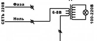
First, this element needs to be de-energized. It is clear that there is no need to deprive it of its power source. It is enough to turn off the electrical appliance and disconnect the plug from the socket. If you approach this issue radically, then for safety you can turn off all the circuit breakers at the switchboard that are responsible for supplying electricity to the room.
Now we need a special device - a multimeter - to find out whether the capacitor is charged.
- Select the mode for measuring DC voltage (direct current).
- We set the device knob to the maximum voltage measurement level.
- We connect the multimeter probes to the contacts of the electronic component. As a rule, two rods protrude from it. It is to them that you need to connect both probes of the detector. You need to press firmly enough so that digital readings appear on the device display. It makes no difference which probe goes to which contact. The resulting value will be the same in both cases.
We need to understand what voltage is at the terminals of the element. Depending on the indications, the discharge method is selected:
- If the reading is less than 10 volts, there is no need to discharge.
- If the display shows measurements between 10–99 volts, you can discharge it with a screwdriver.
- If values are 100 volts or higher, it is recommended to use a discharge device.
Discharge with a screwdriver
First we need a suitable screwdriver with an insulating handle. As a rule, the handles are made of rubber or plastic. Both materials are capable of creating a safe barrier between the hand and the metal part of the screwdriver.
If you are not sure that you have an insulating screwdriver, it is recommended to buy a new one that has a logo with the maximum permissible voltage.
Such tools are sold in the electrical goods department of any hardware department. Both a flathead and a Phillips screwdriver will do.
Now the discharge process itself.
- Grasp the element with one hand at the base, without squeezing too much;
- Place a screwdriver on both terminals;
- A discharge sound and slight sparking will be heard.
Hold the screwdriver so that it touches both legs at the same time, only then the discharge process will occur normally.
To check, you can close the terminals with a screwdriver again.
You can check the degree of discharge with the same multimeter.
Parameters and operating principle
The amount of electricity accumulated by the product, as well as the periods of discharge and charging cycles of the capacitor, are determined by characteristics that depend on the type of specific model. Due to the wide range of parameters and characteristics, these radio components can be successfully used for various purposes.
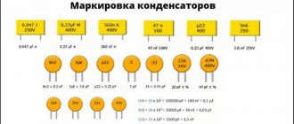
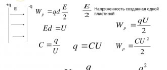
These parameters can be easily determined by the markings on the element body. Capacitors produced in Russia and the post-Soviet space are required to have alphanumeric markings indicating technology and type, TKE, rated voltage, capacitance value and production error, as well as the date of manufacture. For imported analogues, only the capacity designation is typical. In the diagrams, the capacitor is represented by two parallel lines.
Basic and additional parameters:
- Capacity (C) – the ability of a radio component to accumulate electricity (measured in farads). The capacity of the most powerful capacitors reaches several tens of farads.
- Specific capacitance - helps determine the ratio of capacitance to the mass or volume of the product (a very important parameter for microelectronics).
- Rated voltage (Uн) – allows you to determine the limit value at which the capacitor can be operated.
- Polarity is an important parameter, failure to comply with which can lead to failure of the radio element and even an explosion.
- Risk of destruction - to prevent explosion and short circuit, the device may be equipped with a safety valve or special notches on the cover.
There are also parasitic parameters that manufacturers try to reduce when manufacturing products. When choosing radio components, you should take into account stability, capacitance, leakage current, operating voltage, accuracy and temperature coefficient of capacitance.
The principle of operation is the accumulation of electrical charges due to the presence of dielectric material between metal plates on which electrons and ions are collected. Passing through this device, the current strength has the greatest value and the minimum voltage, but as electricity accumulates, the voltage increases, and the current strength, on the contrary, drops until it disappears completely. Under ideal conditions, the charging time of the capacitor is zero.
1.6. Electrical capacity. Capacitors
If two conductors isolated from each other are given charges q1 and q2, then a certain potential difference Δφ arises between them, depending on the magnitude of the charges and the geometry of the conductors. The potential difference Δφ between two points in an electric field is often called voltage and denoted by the letter U. Of greatest practical interest is the case when the charges of the conductors are equal in magnitude and opposite in sign: q1 = – q2 = q. In this case, we can introduce the concept of electrical capacitance.
The electrical capacity of a system of two conductors is a physical quantity defined as the ratio of the charge q of one of the conductors to the potential difference Δφ between them:
In the SI system, the unit of electrical capacity is called farad (F):
The value of electrical capacitance depends on the shape and size of the conductors and on the properties of the dielectric separating the conductors. There are configurations of conductors in which the electric field is concentrated (localized) only in a certain region of space. Such systems are called capacitors, and the conductors that make up the capacitor are called plates.
The simplest capacitor is a system of two flat conducting plates located parallel to each other at a small distance compared to the size of the plates and separated by a dielectric layer. Such a capacitor is called a flat capacitor. The electric field of a flat capacitor is mainly localized between the plates (Fig. 1.6.1); however, a relatively weak electric field also arises near the edges of the plates and in the surrounding space, which is called the stray field. In a number of problems, it is possible to approximately neglect the stray field and assume that the electric field of a flat capacitor is entirely concentrated between its plates (Fig. 1.6.2). But in other problems, neglecting the stray field can lead to gross errors, since the potential nature of the electric field is violated (see § 1.4).
| Figure 1.6.1. Field of a parallel-plate capacitor |
| Figure 1.6.2. An idealized representation of the field of a parallel-plate capacitor. Such a field does not have the property of potentiality |
Each of the charged plates of a flat capacitor creates an electric field near the surface, the intensity modulus of which is expressed by the relation (see § 1.3)
According to the principle of superposition, the field strength created by both plates is equal to the sum of the strengths and fields of each of the plates:
Inside the capacitor, the vectors and are parallel; therefore the modulus of the total field strength is equal to
Outside the plates, the vectors and are directed in different directions, and therefore E = 0. The surface charge density σ of the plates is equal to q / S, where q is the charge and S is the area of each plate. The potential difference Δφ between the plates in a uniform electric field is equal to Ed, where d is the distance between the plates. From these relations we can obtain a formula for the electrical capacitance of a flat capacitor:
Thus, the electrical capacity of a flat capacitor is directly proportional to the area of the plates (plates) and inversely proportional to the distance between them. If the space between the plates is filled with a dielectric, the electrical capacity of the capacitor increases by ε times:
Examples of capacitors with different plate configurations include spherical and cylindrical capacitors. A spherical capacitor is a system of two concentric conducting spheres of radii R1 and R2. A cylindrical capacitor is a system of two coaxial conducting cylinders of radii R1 and R2 and length L. The capacitances of these capacitors filled with a dielectric with dielectric constant ε are expressed by the formulas:
Thus, when connected in parallel, the electrical capacitances add up.
| Capacitors can be connected to each other to form capacitor banks. When connecting capacitors in parallel (Fig. 1.6.3), the voltages on the capacitors are the same: U1 = U2 = U, and the charges are equal to q1 = C1U and q2 = C2U. Such a system can be considered as a single capacitor of electrical capacity C, charged with a charge q = q1 + q2 at a voltage between the plates equal to U. It follows |
| Figure 1.6.3. Parallel connection of capacitors. C = C1 + C2 |
Series connection of capacitors.
When connected in series (Fig. 1.6.4), the charges of both capacitors are identical: q1 = q2 = q, and the voltages across them are equal to and Such a system can be considered as a single capacitor charged with charge q at a voltage between the plates U = U1 + U2. Hence,
When capacitors are connected in series, the reciprocal values of the capacitances are added.
The formulas for parallel and series connections remain valid for any number of capacitors connected to the battery.
| Model. Field of a parallel-plate capacitor |
Types and applications
There are many ways to classify modern capacitors, which allow them to be grouped depending on the type of design, operating voltage, types of polarization and purpose, change in capacitance, and type of dielectric.
Types of polarization:
- ionic and ion-relaxation;
- volumetric;
- dipole-relaxation;
- electronic and electronic relaxation;
- spontaneous.
Based on the design features, there are tubular and cylindrical, monolithic, plate and sectional, disk, pot-shaped and cast, barrel, and sectional varieties.
Scope of application of capacitors:
- Electronics – radio and television equipment, storage devices, automation and various telemechanics, telegraphy and telephony.
- Electrical power engineering - discharge welding, starting electric motors, radio interference suppression, voltage regulation, electric lighting, energy extraction, use in complex circuits and generators, and voltage protection.
- Industry – mining, metallurgy and metalworking.
- Equipment – medical, laser, electrical measuring, radar, photographic, automotive.
Depending on the change in capacitance, there are constant, variable (the change is carried out mechanically or electrically) and tuning capacitors (the change is carried out one-time or periodically).
What is a capacitor?
A device that stores electricity in the form of electrical charges is called a capacitor.
The amount of electricity or electric charge in physics is measured in coulombs (C). Electrical capacitance is calculated in farads (F).
A solitary conductor with an electrical capacity of 1 farad is a metal ball with a radius equal to 13 radii of the Sun. Therefore, a capacitor includes at least 2 conductors, which are separated by a dielectric. In simple device designs, paper is used.
The operation of a capacitor in a DC circuit is carried out when the power is turned on and off. Only during transient moments does the potential on the plates change.
The capacitor in the AC circuit recharges at a frequency equal to the frequency of the power source voltage. As a result of continuous charges and discharges, current flows through the element. A higher frequency means the device recharges faster.
The resistance of the circuit with a capacitor depends on the frequency of the current. At zero frequency of direct current, the resistance value tends to infinity. As the AC frequency increases, the resistance decreases.
Alternating current
Gentlemen, in today’s article I would like to consider such an interesting issue as a capacitor in an alternating current circuit
. This topic is very important in electricity, since in practice capacitors are ubiquitous in circuits with alternating current and, in this regard, it is very useful to have a clear understanding of the laws by which signals change in this case. We will consider these laws today, and at the end we will solve one practical problem of determining the current through a capacitor.
Gentlemen, now the most interesting point for us is how the voltage on the capacitor and the current through the capacitor are related to each other for the case when the capacitor is in the alternating signal circuit.
Why immediately variable? Yes, simply because the capacitor in the DC circuit is unremarkable. Current flows through it only at the first moment while the capacitor is discharged. Then the capacitor is charged and that’s it, there is no current (yes, yes, I hear people have already started shouting that the charge of the capacitor theoretically lasts for an infinitely long time, and it may also have a leakage resistance, but for now we are neglecting this). A charged capacitor for direct current is like an open circuit. When we have the case of alternating current, everything is much more interesting. It turns out that in this case, current can flow through the capacitor and the capacitor in this case is equivalent to a resistor with some well-defined resistance (if you forget about all sorts of phase shifts for now, more on that below). We need to somehow obtain a relationship between the current and voltage across the capacitor.
For now we will assume that in the AC circuit there is only a capacitor and that’s it. Without any other components such as resistors or inductors. Let me remind you that in the case when we have only resistors in the circuit, such a problem is solved very simply: the current and voltage are connected to each other through Ohm’s law. We have talked about this more than once. Everything is very simple there: divide the voltage by the resistance and get the current. But what about the capacitor? After all, a capacitor is not a resistor. The physics of the processes there is completely different, so it’s not possible to simply connect current and voltage with each other just like that. Nevertheless, this must be done, so let's try to reason.
First let's go back. Far back. Even very far away. To my very, very first article on this site. Old-timers may remember that this was an article about current strength. In this very article there was one interesting expression that connected the strength of the current and the charge flowing through the cross-section of the conductor. This is the very expression
Someone might object that in that article about current strength, the entry was in terms of Δq and Δt - some very small values of the charge and the time during which this charge passes through the cross section of the conductor. However, here we will use writing through dq and dt - through differentials. We will need such a representation later. If you don’t go deep into the wilds of matan, then essentially dq and dt here are not particularly different from Δq and Δt . Of course, people deeply knowledgeable in higher mathematics can argue with this statement, but right now I don’t want to concentrate on these things.
So, we remembered the expression for current strength. Let's now remember how the capacitance of the capacitor C , the charge q that it has accumulated in itself, and the voltage U on the capacitor that was formed are related to each other. Well, we remember that if a capacitor has accumulated some kind of charge, then voltage will inevitably arise on its plates. We also talked about this all before, in this article. We will need this formula, which just connects charge with voltage
Let's express the charge of the capacitor from this formula:
And now there is a very big temptation to substitute this expression for the charge of the capacitor into the previous formula for the current strength. Take a closer look - then the current strength, capacitance of the capacitor and voltage on the capacitor will be interconnected! Let's do this substitution without delay:
The capacitance of the capacitor is a constant
.
It is determined solely by the capacitor itself
, its internal structure, the type of dielectric and all that other stuff.
We talked about all this in detail in one of the previous articles. Consequently, the capacitance C
of the capacitor, since it is a constant, can be safely taken out as the sign of the differential (these are the rules for working with these same differentials).
But
you can’t do this
U The voltage across the capacitor will change over time .
Why is this happening? The answer is elementary: as current flows across the plates of the capacitor, obviously, the charge will change. And a change in charge will certainly lead to a change in the voltage across the capacitor. Therefore, voltage can be considered as a certain function of time and cannot be removed from under the differential. So, having carried out the above-mentioned transformations, we get the following entry: Gentlemen, I hasten to congratulate you - we have just received a very useful expression that relates the voltage applied to the capacitor and the current that flows through it. Thus, if we know the law of change of voltage, we can easily find the law of change of current through a capacitor by simply finding the derivative.
But what about the opposite case? Let's say we know the law of change in current through a capacitor and we want to find the law of change in voltage across it. Readers knowledgeable in mathematics have probably already guessed that to solve this problem it is enough to simply integrate the expression written above. That is, the result will look something like this:
In fact, both of these expressions are about the same thing. It’s just that the first is used in the case when we know the law of change in voltage across the capacitor and we want to find the law of change in the current through it, and the second when we know how the current changes through the capacitor and we want to find the law of change in voltage. To better remember this whole matter, gentlemen, I have prepared an explanatory picture for you. It is shown in Figure 1.
Figure 1 – Explanatory picture
It essentially depicts conclusions in a condensed form that would be good to remember.
Gentlemen, please note that the resulting expressions are valid for any law of change in current and voltage.
There does not have to be a sine, cosine, meander or anything else.
If you have some completely arbitrary, even completely wild, not described in any literature, law of change in voltage U(t) applied to a capacitor, by differentiating it you can determine the law of change in current through the capacitor. And similarly, if you know the law of change in current through the capacitor I(t) , then by finding the integral, you can find how the voltage will change.
So, we found out how to connect current and voltage with each other for absolutely any, even the most crazy options for changing them. But some special cases are no less interesting. For example, the case of sinusoidal current, which we all have already come to love. Let's deal with it now.
Let the voltage across a capacitor of capacitance C
changes according to the law of sine in this way
We discussed in detail a little earlier what physical quantity stands behind each letter in this expression. How will the current change in this case? Using the knowledge we have already gained, let's just stupidly substitute this expression into our general formula and find the derivative
Or you can write it like this
Gentlemen, I want to remind you that the only difference between sine and cosine is that one is shifted in phase relative to the other by 90 degrees. Well, or, if expressed in the language of mathematics, then . It is not clear where this expression came from? Google reduction formulas
.
It's a useful thing, it wouldn't hurt to know. And even better, if you are familiar with the trigonometric circle
, all this can be seen very clearly on it.
Gentlemen, I will immediately note one point. In my articles I will not talk about the rules for finding derivatives and taking integrals. I hope you have at least a general understanding of these points. However, even if you don’t know how to do this, I will try to present the material in such a way that the essence of things is clear even without these intermediate calculations. So, now we have received an important conclusion - if the voltage on the capacitor changes according to the sine law, then the current through it will change according to the cosine law. That is, the current and voltage on the capacitor are shifted relative to each other in phase by 90 degrees.
In addition, we can relatively easily find the amplitude value of the current (these are the factors that appear in front of the sine).
Well, that is, that peak, that maximum that the current reaches. As we can see, it depends on the capacitance C
Um
applied to it and the frequency
ω
. That is, the greater the applied voltage, the greater the capacitance of the capacitor and the greater the frequency of voltage change, the greater the amplitude of the current through the capacitor. Let's build a graph, depicting in one field the current through the capacitor and the voltage across the capacitor. Without specific numbers yet, we’ll just show the quality of the character. This graph is presented in Figure 2 (the picture is clickable).
Figure 2 – Current through the capacitor and voltage across the capacitor
In Figure 2, the blue graph is the sinusoidal current through the capacitor, and the red graph is the sinusoidal voltage across the capacitor. From this figure it is very clearly visible that the current leads the voltage (the peaks of the current sinusoid are to the left of the corresponding peaks of the voltage sinusoid, that is, they come earlier).
Let's now do the work in reverse. Let us know the law of change in current I( t)
through a capacitor of
capacitance C. And let this law also be sinusoidal
Let's determine how the voltage on the capacitor will change in this case. Let's use our general formula with the integral:
By absolute analogy with the calculations already written, the tension can be represented in this way
Here we again took advantage of interesting information from trigonometry that. And again the reduction formulas
they will come to your aid if it is not clear why it happened this way.
What conclusion can we draw from these calculations? And the conclusion is still the same as has already been made: the current through the capacitor and the voltage on the capacitor are shifted in phase relative to each other by 90 degrees. Moreover, they are shifted for a reason. Current leads
voltage. Why is this so? What is the physics of the process behind this? Let's figure it out.
Let's imagine that uncharged capacitor to a voltage source. At the first moment there are no charges in the capacitor at all: it is discharged. And since there are no charges, then there is no voltage. But there is a current, it appears immediately when the capacitor is connected to the source. Do you notice, gentlemen? There is no voltage yet (it has not had time to increase), but there is already current . And besides, at this very moment of connection, the current in the circuit is maximum (a discharged capacitor is essentially equivalent to a short circuit in the circuit). So much for the lag between voltage and current. As current flows, charge begins to accumulate on the plates of the capacitor, that is, the voltage begins to increase and the current gradually decreases. And after some time, so much charge will accumulate on the plates that the voltage on the capacitor will be equal to the source voltage and the current in the circuit will stop completely.
Now let's disconnect this very charged capacitor from the source and short-circuit it. What will we get? But practically the same. At the very first moment, the current will be maximum, and the voltage on the capacitor will remain the same as it was without changes. That is, again the current is ahead, and the voltage changes after it. As the current flows, the voltage will begin to gradually decrease and when the current stops completely, it will also become zero.
To better understand the physics of the ongoing processes, you can once again use the plumbing analogy . Let's imagine that a charged capacitor is a tank full of water. This tank has a tap at the bottom through which you can drain the water. Let's open this tap. As soon as we open it, water will flow immediately. And the pressure in the tank will drop gradually as the water flows out. That is, roughly speaking, a trickle of water from a faucet outpaces the change in pressure, just as the current in a capacitor outpaces the change in voltage across it.
Similar reasoning can be carried out for a sinusoidal signal, when the current and voltage change according to the sine law, and indeed for any signal. The point, I hope, is clear.
Let's do a little practical calculation of the AC current through a capacitor and plot the graphs.
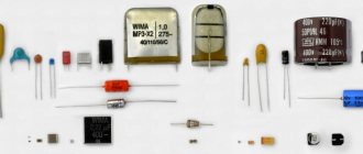
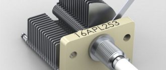
Let us have a source of sinusoidal voltage, the effective value is 220 V , and the frequency is 50 Hz . Well, that is, everything is exactly the same as in our sockets. 1 µF capacitor is connected to this voltage . For example, film capacitor K73-17 , designed for a maximum voltage of 400 V (and capacitors for lower voltages should never be connected to a 220 V network), is available with a capacity of 1 μF. To give you an idea of what we are dealing with, in Figure 3 I have placed a photograph of this animal (thanks to Diamond for the photo)
Figure 3 – Looking for current through this capacitor
It is required to determine what current amplitude will flow through this capacitor and construct graphs of current and voltage.
First we need to write down the law of voltage change in an outlet. If you remember, the amplitude
the voltage value in this case is about 311 V. Why this is so, where it came from, and how to write down the law of voltage changes in an outlet can be read in this article. We will immediately present the result. So, the voltage in the outlet will change according to the law
Now we can use the formula obtained earlier, which will relate the voltage in the outlet to the current through the capacitor. The result will look like this
We simply substituted into the general formula the capacitance of the capacitor specified in the condition, the amplitude value of the voltage and the circular frequency of the network voltage. As a result, after multiplying all the factors we have the following law of current change:
That's it, gentlemen. It turns out that the amplitude value of the current through the capacitor is slightly less than 100 mA. Is it a lot or a little? The question cannot be called correct. By the standards of industrial equipment, where hundreds of amperes of current appear, this is very little. And for household appliances, where tens of amperes are not uncommon - too. However, even such a current poses a great danger to humans! From this it follows that you should not grab such a capacitor connected to a 220 V network. However, on this principle it is possible to manufacture so-called power supplies with a quenching capacitor. Well, this is a topic for a separate article and we will not touch on it here.
All this is good, but we almost forgot about the graphs that we must build. We need to fix it urgently! So, they are presented in Figure 4 and Figure 5. In Figure 4 you can see a graph of the voltage in the socket, and in Figure 5 - the law of change in current through a capacitor connected to such a socket.
Figure 4 – Outlet voltage graph
Figure 5 – Graph of current through a capacitor
As we can see from these pictures, the current and voltage are shifted by 90 degrees, as they should be. And perhaps the reader has an idea - if current flows through a capacitor and some voltage drops across it, probably some power should also be released across it. However, I hasten to warn you - for a capacitor the situation is completely different . If we consider an ideal capacitor, then no power will be released on it at all, even when current flows and the voltage drops across it. Why? How so? More on this in future articles. That's all for today. Thank you for reading, good luck, and see you next time!
Join our VKontakte group
Questions and suggestions to the admin: This email address is being protected from spambots. You need JavaScript enabled to view it.
Social button for Joomla
It's better to check first
First, this element needs to be de-energized. It is clear that there is no need to deprive it of its power source. It is enough to turn off the electrical appliance and disconnect the plug from the socket. If you approach this issue radically, then for safety you can turn off all the circuit breakers at the switchboard that are responsible for supplying electricity to the room.
Now we need a special device - a multimeter - to find out whether the capacitor is charged.
- Select the mode for measuring DC voltage (direct current).
- We set the device knob to the maximum voltage measurement level.
- We connect the multimeter probes to the contacts of the electronic component. As a rule, two rods protrude from it. It is to them that you need to connect both probes of the detector. You need to press firmly enough so that digital readings appear on the device display. It makes no difference which probe goes to which contact. The resulting value will be the same in both cases.
We need to understand what voltage is at the terminals of the element. Depending on the indications, the discharge method is selected:
- If the reading is less than 10 volts, there is no need to discharge.
- If the display shows measurements between 10–99 volts, you can discharge it with a screwdriver.
- If values are 100 volts or higher, it is recommended to use a discharge device.
DIY discharge device
Before measuring the capacity, check the condensers for breakdown or leakage, or if you need to replace a faulty element, you need to discharge it. It is especially important to make the correct discharge for high-voltage, high-capacity radio components. The accumulated energy can persist for a long time and improper dismantling or storage can pose a threat to life.
An inexpensive, easy-to-implement electronic device can be assembled to safely discharge high-voltage capacitors. It discharges quite efficiently and safely.
Let's look at its circuit diagram:
The voltage from the high-voltage capacitor is supplied to the quenching resistor R1 and then goes to a double-sided diode voltage limiter.
The diode limiter itself consists of two parallel chains of diodes D1-D3 and D4-D6. This is done in order to remove a voltage of about 2 volts from any diode in the circuit for the operation of LED indicators D7, D8. The incoming current to the LEDs is limited by resistor R2.
The LED starts the process of discharging the high-voltage capacitor to a safe voltage of about two volts.
The discharge process may take some time from 10 seconds. and more. The discharge time depends on the capacity of the connected condenser and what residual voltage remains in it.
As soon as the LED goes out, you can carry out the final discharge by short-circuiting the terminals of the radio component using a screwdriver.
The scheme is quite workable.
The entire board can be assembled independently and placed in a plastic case.
Methods for charging and discharging a capacitor
When charging a capacitor, the energy of the power source is converted into the energy of the electric field that arises between the metal plates of the radio-electronic device. It is important to consider that at each section of the circuit there is explicit (resistor) or implicit resistance (wires, internal resistance). In this case, the charging rate of the capacitor will depend on its capacitance and resistance in the entire circuit. The process is considered complete when the applied voltage becomes equal in magnitude to the voltage on the metal plates.
The process of charging and discharging a capacitor is best determined with a multimeter or using a special measuring device - an indicator screwdriver.
You can charge a capacitor through a light bulb. To do this, you will need to connect the “plus” to the battery through a car light bulb, and connect the “minus” to ground (car body). The light will flash and go out. In the same way, you can charge a capacitor for a subwoofer if it does not have a charging current control system. This capacitor charging scheme is effective, simple and safe.
Discharging may be necessary when repairing household appliances and electronic devices. This can be done using a screwdriver with an insulated handle, closing the contacts one by one, while simultaneously touching the ground with the screwdriver shaft. If the capacitor is removed from the board, it is necessary, without touching the contacts with your hands, to apply the screwdriver rod to both terminals of the product (a spark should appear). You can also assemble a discharge device by soldering two wires with clamps to a resistor (several kOhms), and then connecting them to the terminals of the capacitor. It is important to check the voltage to make sure the device is sparse.
Purpose and functions of capacitors
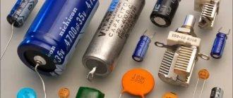
The capacitor plays a huge role in both analog and digital technology. They are electrolytic and ceramic, and differ in their properties, but not in their overall concept. Examples of using:
- Filters high-frequency interference;
- Reduces and smoothes pulsations;
- Separates the signal into constant and variable components;
- Accumulates energy;
- Can be used as a voltage reference;
- Creates resonance with the inductor to amplify the signal.
Examples of using
In amplifiers they are usually used to protect subwoofers, power filtering, thermal stabilization and separation of DC and AC components. And electrolytic ones in autonomous circuits with microcontrollers can provide power for a long time due to their large capacity.
In this circuit, transistor VT1 is constantly open to amplify the sound without distortion. But if the input gets stuck or a direct current flows into it, the transistor will open, go into saturation and overheat. To prevent this, you need a capacitor. C1 allows you to separate the constant component from the variable. The alternating signal easily passes to the base of the transistor, but the constant signal does not.
C2, together with resistor R3, performs the function of thermal stabilization. When the amplifier is running, the transistor gets hot. This may introduce distortion into the signal. Therefore, resistor R3 helps maintain the operating point when heating. But when the transistor is cold and stabilization is not required, a resistor can reduce the power of the amplifier. Therefore, C2 comes into play. It conducts the amplified signal through itself by shunting a resistor, thereby not reducing the rated power of the circuit. If its capacitance is lower than designed, it will begin to introduce phase distortion into the output signal.
For the scheme to work well, good nutrition is a must. When a circuit consumes more current at peak values, it is always a heavy load on the power supply. C3 filters power interference and helps reduce the load. The larger the capacitance, the better the sound, but up to certain values, it all depends on the circuit.
And the power supplies use the same principle as in the previous power supply scheme, but here the capacity is needed much more. In this circuit, the capacitance of the electrolyte can be either 1000 μF or 10,000 μF.
You can also connect ceramic capacitors in parallel to the diode bridge, which will bypass the circuit from high-frequency interference and noise from the 220 V network.
Phase distortion
A capacitor can distort the AC signal's phase. This occurs due to incorrect calculation of capacitance, total resistance and interaction with other radio components. We should not forget that any radio component has both reactive and active resistance.
Source
Educational program KO. Lecture No. 2 Capacitor.
Capacitor (capacitance) Capacitor (capacitance)
– an element capable of accumulating electromagnetic energy in its own electric field formed by the capacitor plates.
by
– C. The voltage and current at its contacts are related by the following relationship: The capacitance value is measured in farads (F). 1 farad
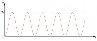
is the value of a capacitance across which a voltage drop of 1 volt occurs when there is a charge in the capacitance of 1 coulomb. 1 farad is a very large value, therefore the capacitors used in technology have the following values: - picofarads - 10-12; nanofarad – 10-9; microfarad – 10-6. The processes occurring in the capacitor on a time graph when the capacitor is connected to a source of a rectangular unipolar signal are shown in the figure. The figure shows that at the moment a rectangular pulse of the current source (red) is applied, the voltage at the terminals of the capacitor (purple) is initially zero and increases exponentially with time - the capacitor is charged, and the capacitor current (green), on the contrary, is at first maximum, but then As the charge increases, it decreases exponentially. When the pulse disappears, the voltage at the terminals of the capacitor decreases exponentially - the capacitor is discharged, and the current that has changed polarity is initially maximum, and as it discharges, it decreases from the negative region to zero. The rate of change of voltage and current depends on the value of the capacitance. The larger the capacity, the slower they change (the exponential is longer in time). The voltage and current across the load resistor behave the same and are shown in orange on the timing graph. Their relationship is described by Ohm's law. In fact, we looked at a “quadripole” consisting of a capacitor and a resistor, which is called a differentiating circuit.
Differentiation chain
used to convert long-duration rectangular pulses into short-duration rectangular pulses.
To make it clearer to you, the differentiating chain and pulse transformation are shown in the following figure. Following the differentiating chain, a threshold device is installed that does not pass through everything that is lower in amplitude of the set threshold, from the output of the threshold device, the cut off pulses are sent to a limiting amplifier, which amplifies the “curve” pulse and, limiting its amplitude “from above”, passes it to exit. In addition to the function of converting rectangular pulses, the differentiating chain can be used as a high-pass filter (HPF)
.
The capacitor is an inert element. If a low-frequency alternating voltage is applied to a capacitor with a large capacitance, due to its inertia, the capacitor will not be able to pass current through itself, because the capacitor will first need to charge and then release the charge. The property of a capacitor to resist alternating electric current is called capacitor reactance
, which is used in the design of frequency filters and oscillating circuits.
The reactance of a capacitor is designated Xc
or
Zc
and is measured in Ohms.
The reactance of a capacitor is related to its own capacitance and current frequency by the expression: From the formula it can be seen that the reactance of a capacitor is inversely proportional to frequency. In other words, the higher the frequency, the lower the reactance of the capacitor
.
Now imagine that the differentiating circuit is a voltage divider, where instead of the first resistor there is a capacitor. And we now know from the formula that a capacitor easily transmits high frequencies - its resistance is minimal and does not transmit low frequencies well - its resistance is maximum. In radio electronics, when frequency filters are calculated, the filter characteristic is considered to be the cutoff frequency, which is defined as the value of the signal frequency at which the amplitude of the output signal decreases (attenuates) to a value of 0.7 from the input signal. To make it clearer, I will depict this in a drawing. What is depicted is called the amplitude-frequency response
, or abbreviated as
frequency response
.
For a high-pass filter, the frequency response is purple, and the cutoff frequency is equal to the value f2
.
Knowing how the voltage divider and capacitor reactance are calculated at a certain frequency, you can easily calculate the simplest L-shaped filter
high frequency on a capacitor and resistor.
If we swap the capacitor and resistor in the differentiating chain, we get an integrating chain
.
All processes in the integrating chain occur in exactly the same way as in the differentiating chain. The time graphs shown in the first figure are absolutely valid for the integrating chain. The difference is that the output element is not a resistor, but a capacitor. Therefore, at the output of the integrating circuit there will be not pointed differentiated pulses (green), but voltage pulses that are present at the terminals of the capacitor (purple). Well, if the differentiating chain is a high-pass filter, then the integrating chain is a low-pass filter (LPF)
.
And it is calculated in the same way, through a voltage divider. For a low-pass filter, the frequency response in the figure is orange, and the cutoff frequency is equal to the value f1
.
It should be added that frequency filters made on capacitors and resistors have a flat amplitude-frequency characteristic. In other words, such filters have a weakly defined frequency cutoff. Filters consisting of capacitors and inductors (chokes) have a better cut, but more on that later, when we study the inductor. Parallel connection of capacitors
The total capacitance of capacitors in a parallel connection is equal to their sum.
Series connection of capacitors
The value inversely proportional to the total capacitance of the capacitors when connected in series is equal to the sum of the values inversely proportional to their capacitance. For two capacitors connected in series, their total capacitance is:
Tips and warnings
After the discharge process is completed, you can wrap its terminals with foil so that this radio component remains discharged. All capacitors can eventually discharge on their own after a few days, provided they are not connected to external power sources. But it is always better to assume that they are in a charged state and a test discharge will not be superfluous. It is necessary to constantly remember that large radio components that switch electricity are very dangerous.
Working with such radio components requires professional skills. Always take safety precautions when working with electrical devices.
Rated voltage
The second most important characteristic after capacitance is the maximum rated voltage of the capacitor
. This parameter indicates the maximum voltage that the capacitor can withstand. Exceeding this value leads to “punching” of the insulator between the plates and a short circuit. The rated voltage depends on the insulator material and its thickness (the distance between the plates).
It should be noted that when working with alternating voltage, it is the peak value (the highest instantaneous voltage value per period) that needs to be taken into account. For example, if the effective voltage of the power supply is 50V, then its peak value will be over 70V. Accordingly, it is necessary to use a capacitor with a rated voltage greater than 70V. However, in practice, it is recommended to use a capacitor with a voltage rating of at least twice the maximum possible voltage that will be applied to it.
Discharge with a screwdriver
First we need a suitable screwdriver with an insulating handle. As a rule, the handles are made of rubber or plastic. Both materials are capable of creating a safe barrier between the hand and the metal part of the screwdriver.
If you are not sure that you have an insulating screwdriver, it is recommended to buy a new one that has a logo with the maximum permissible voltage.
Such tools are sold in the electrical goods department of any hardware department. Both a flathead and a Phillips screwdriver will do.
Now the discharge process itself.
- Grasp the element with one hand at the base, without squeezing too much;
- Place a screwdriver on both terminals;
- A discharge sound and slight sparking will be heard.
Hold the screwdriver so that it touches both legs at the same time, only then the discharge process will occur normally.
To check, you can close the terminals with a screwdriver again.
You can check the degree of discharge with the same multimeter.
Characteristics and properties
Capacitor parameters that are used to create and repair electronic devices include:
- Capacity - C. Determines the amount of charge that the device holds. The value of the nominal capacity is indicated on the case. To create the required values, the elements are included in the circuit in parallel or in series. Operational values do not coincide with calculated values.
- Resonant frequency - fр. If the current frequency is greater than the resonant one, then the inductive properties of the element appear. This makes work difficult. To ensure the design power in the circuit, it is reasonable to use a capacitor at frequencies below resonant values.
- Rated voltage - Un. To prevent breakdown of the element, the operating voltage is set less than the rated voltage. The parameter is indicated on the capacitor body.
- Polarity. If the connection is incorrect, breakdown and failure will occur.
- Electrical insulation resistance - Rd. Determines the leakage current of the device. In devices, parts are located close to each other. At high leakage current, parasitic connections in the circuits are possible. This leads to malfunctions. Leakage current worsens the capacitive properties of the element.
- Temperature coefficient - TKE. The value determines how the capacitance of the device changes with fluctuations in ambient temperature. The parameter is used when developing devices for operation in harsh climatic conditions.
- Parasitic piezoelectric effect. Some types of capacitors create noise in devices when deformed.
How does he work
If you disassemble the capacitor, its structure is quite simple. These are two electrodes separated by a dielectric material:
- by air,
- ceramic material,
- impregnated paper.
The capacitor plates act as electrodes. It is in them that the process of accumulation of electrical energy occurs from the moment voltage is applied to the plates. If voltage is not applied, then under the influence of electrostatic attraction, the accumulated energy is stored on the plates of the capacitor.
Permanent type condensers are divided into:
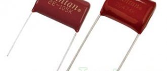
- Film. They consist of a three-layer film according to the electrode-dielectric-electrode scheme. The film is rolled up and placed in the housing. They are widely used in electrical circuits of household appliances.
- Ceramic. They consist of ceramic plates with metal electrodes. To discharge them, it is better to use a load with high resistance.
The unit of capacity of this element is considered to be the farad. That is, if a conductor has a capacity of 1 farad, then it is capable of generating 1 volt.
In electronics and electrical engineering, elements are used whose capacitance can be measured:
- picofarads,
- nanofarads,
- microfarads,
- millifarads.
The capacity indicated on the element’s body is a nominal value that is practically impossible to obtain. Therefore, the percentage tolerance of its capacitance is indicated on the capacitor. This should be understood as the percentage deviation of the real value from the nominal value.
Characteristics of capacitors
The main characteristic of a device is capacity, that is, the amount of energy that it can accumulate in the form of electrons. The total number of charges on the plates determines the capacitance value of the capacitor.
Note ! The capacitance depends on the area of the plates and the dielectric constant of the material. The larger the area of the capacitor plates, the more charged particles can fit on them and the higher the capacitance.
Capacity
The most important characteristics include specific capacitance, density, nominal charge force and polarity. Additional parameters include the number of phases, capacitor installation method, operating temperature, active electric current of alternating or direct type.
In electrical engineering, there are also concepts of negative factors that distort the operating properties of an oscillatory circuit. These include electrical resistance and equivalent series inductance. An example of a negative criterion is an indicator showing a drop in charge after a power outage.
You may be interested in this Determination of polarity
How to discharge high-voltage non-polar capacitors without damaging the capacitors themselves?
There is about 450VAC 700uF (connected in parallel), no matter where or how, the main thing is that we have charged capacitors and they need to be discharged. The option with shorted terminals is immediately bypassed - sooner or later this will kill the capacitors, and they will be charged and discharged frequently
The discharge should occur in 1-3 minutes maximum
Zero # 2022.09.30 07:01 0
User replies: score 0 : 0 won't hit anything
Well, then use a shunt of a few kilo-ohms or so, what’s the problem?
Oxotnick # 2022.09.30 20:45 0
User Answers:Simply….
Resistor 100 kOhm 2W parallel to the conductors
Olenka # 2022.10.01 11:40 0
User Answers: Balotelli anyway)
Have you tried using a resistor? Discharge time to 95% (those up to 5% of residual charge) t = 3 RC
Kradun # 2022.10.01 18:44 0
User Answers: Two-wheeled ****
These are by no means high-voltage capacitors...
DolmakimiOglan # 2022.10.02 01:06 0
User Answers: Lights up.
When operating in a 220 V network, as a starting capacitor in an engine, a current of at least 50 A will flow through it. The capacitance of a 700 µF capacitor will be about 4-5 Ohms. Therefore, the game is not worth the candle. You can discharge through a 30 Ohm resistor, preferably a 10 Watt. The flash lamp uses an 800 uF, 450 V capacitor and it discharges with almost a short circuit and nothing! Considering the huge area of the capacitor plates, the danger is only for the conductors leading to them. Yes, and even then, it is most likely exaggerated.
Elvis # 2022.10.02 06:54 0
User Answers: Why pay attention to a former chess player who has gone crazy?
well)))) if you have to, tell me - no answer - straight))))) - in public here!!!! vivalostioz # 2022.10.02 23:26 0
User answers: Free education and medicine...practically none, a rare product in rare salads on rare holiday tables)...Yandex to help!
Through a 5-10 kOhm resistor
BOKSYOR # 2022.10.03 01:05 0
User Replies:Lady Gaga
700uF/450V???? Two series-connected 60-100 watt lamps and the whole problem... or a 500 ohm 10 watt resistor, even a simple wire-wound one! You won’t even see sparks, but it’s painless for the wires and the resistor itself... it won’t even heat up... I did this myself when I soldered the drive at night and everyone was asleep... By the way: Kander won’t give a damn even from the short circuit!!! If it’s non-polar! Tested for years)))
Kill_Me_Gently # 2022.10.03 05:19 0
User Answers: I just took advantage of the opportunity to correct my figure - both ours and yours.
This is a large capacity, you cannot short-circuit, a resistor of about 10 - 50 kohm can be equipped with a thyristor, press the button, and there is no problem...
Zoot # 2022.10.03 05:51 0
User questions: Why is it necessary to undress completely in front of students before surgery, maybe I don’t want to be stared at? I’m constantly nervous about work, I don’t sleep well, I’m losing weight. I work as a teacher at school and the work is very stressful. Which is better i5 8400 or Ryzen 5 2600?
actually using a rod with a resistor and discharging it..
PEPBI3TSIK # 2022.10.03 09:33 0
User Answers:Your roof is on fire - call 01! You need a roof - call 02! You've gone crazy - call 03! Do you need......no.. they disappear somewhere on their own)
Bridge the resistance.
BRIQADIR # 2022.10.04 13:55 0
User replies:hate...It's difficult to find a song based on your information. Try online music recognition programs: Tunatic,...An ax to the head
I advise you to read this
WARLOCK # 2022.10.05 12:17 0
User replies: “...people stopped...” People, imagine, didn’t even start.
2 incandescent lamps 220V 100W in series. I turned on the toggle switch - the discharge began, and at the same time the indication began. If they go out completely, it means they are discharged
KRUTOY # 2022.10.06 00:29 0
User's responses: He wants to quickly get drunk on the road... You look through the sight... you aim... you shoot.. BINGOO... but no, you missed (that's how the sight works: D... Oooh, his look of loving eyes can incinerate...
Starting 700uF... This is a 7.5 kW motor. How will your network hold up? There, the starting current will sag the entire line, and the neighbors along the entire street will be indignant....
Capacitor energy
A capacitor, like any system of charged bodies, has energy. To charge a capacitor, work must be done to separate negative and positive charges. According to the law of conservation of energy, this work will be exactly equal to the energy of the capacitor.
It is not difficult to prove that a charged capacitor has energy. To do this, you will need an electrical circuit containing an incandescent lamp and a capacitor. When the capacitor discharges, the lamp will flash - this will mean that the energy of the capacitor has been converted into heat and light energy.
To derive the formula for the energy of a flat capacitor, we need the formula for the energy of the electrostatic field.
| Electrostatic field energy Wp = qEd Wp – electrostatic field energy [J] q —electric charge [C] E – electric field strength [V/m] d —distance from charge [m] |
In the case of a capacitor, d will represent the distance between the plates.
The charge on the capacitor plates is equal in magnitude, so we can consider the field strength created by only one of the plates.
The field strength of one plate is equal to E/2 , where E is the field strength in the capacitor.
In a uniform field of one plate there is a charge q distributed over the surface of the other plate.
Then the energy of the capacitor is:
Wp = qEd/2
The potential difference between the plates of a capacitor can be represented as the product of voltage and distance:
U = Ed
That's why:
Wp = qU/2
This energy is equal to the work done by the electric field when the plates are brought closer together.
Replacing the potential difference or charge in the formula using the expression for the electrical capacity of the capacitor C = q/U , we obtain three different formulas for the energy of the capacitor:
| Capacitor energy Wp = qU/2 Wp – electrostatic field energy [J] q —electric charge [C] U – voltage across the capacitor [V] |
| Capacitor energy Wp = q2/2C Wp – electrostatic field energy [J] q —electric charge [C] C —capacitance of the capacitor [F] |
| Capacitor energy Wp = CU2/2 Wp – electrostatic field energy [J] C —capacitance of the capacitor [F] U – voltage across the capacitor [V] |
These formulas are valid for any capacitor.
How to Calculate Impedance in a Circuit
Impedance is the total R of the current, which is denoted by Z. This parameter is a reflection of the time-varying value of the current. Impedance is a vector quantity that consists of two values: active and reactance.
The active part of the impedance, denoted R, is a measure of the degree to which a material will resist the movement of electrons between atomic particles. The more easily atomic particles release or accept electrons, the lower the resistance.
Materials with minimal resistance include steel, aluminum, and gold. The highest R values are glass, mica, polyethylene and are most often called insulators or dielectrics.
If resistors are used in sinusoidal current circuits, the term "impedance" will be used to indicate resistance R=Z.
Practical impedance calculations are most often performed using the following formula:
Z = Um/Im.
Reactance is denoted by X and is an expression of the degree to which an electronic component in a circuit will store or release electrical energy as the current and voltage fluctuate with each cycle. Reactance is expressed in ohms.
Energy will be stored and released in two types:
- Magnetic field. The reactive part is inductive.
- Electric field.
What is the difference between polar and non-polar?
Non-polar ones allow the inclusion of capacitors in a circuit without taking into account the direction of the current. The elements are used in filters for variable power supplies and high-frequency amplifiers.
Polar products are connected in accordance with the markings. If turned on in the reverse direction, the device will be damaged or will not work normally.
Polar and non-polar capacitors of large and small capacity differ in dielectric design. In electrolytic capacitors, if the oxide is applied to 1 electrode or 1 side of the paper, film, then the element will be polar.
Models of non-polar electrolytic capacitors, in the designs of which the metal oxide is deposited symmetrically on both surfaces of the dielectric, are included in circuits with alternating current.
Polar ones have a positive or negative electrode marking on the body.
Device energy
It is impossible to charge a capacitor instantly. This process requires some time. This phenomenon is used in radio engineering. So, with the help of a capacitor, pulse bursts are smoothed out. To a first approximation, a capacitor is similar to a battery. But at the same time, it differs from it in the principle of energy storage , capacity and charge-discharge rate. When a power source is connected to the terminals of the device plates, the capacitor accumulates charge on them.~
The operation of the device can be explained by analogy with the flow of water. Let there be a vessel with a liquid with a cross-sectional area S. In fact, this is the equivalent of a container. Then the water will be a charge, and the height of the water column will be a voltage. It turns out that energy is the product of charges and height. But if a battery can be imagined as a vessel in which there is a thin hose (lead) and through which water flows (charge), then in a capacitor its tube diameter will be equal to the size of the entire jar. That is, the device can instantly release all the accumulated charge.
When voltage is applied to the plates, the dielectric becomes electrified. As a result, a displacement occurs and energy is transferred to the plates. On one of them there will be an excess of electrons, and it will be conditionally charged negatively, and on the second there will be a deficiency - the conductor will become positive. Therefore, in the formula that determines the charge on the capacitor plates, the dielectric constant of a non-conducting substance is of great importance.
Force arises between the plates. The magnitude acting from the first side is equal to F = ε1 * q, and from the second side F = ε2 * q. Thus, we can write: F = ε1 * q = ε2 * q = E / 2 * q. When the distance between the plates increases from zero to d, the work will be performed: A = F * d. It is aimed at overcoming the interaction force between charged conductors.
That is: A = E / 2 * q * d. Based on the fact that ε = U/d it will be correct to write: A = 1 / 2 q * U. This means that the mechanical work A in accordance with the law of conservation of energy will be equal to the number of charges stored in the electric field of the capacitor: We = C * U2 / 2.
It should be noted that when an alternating signal is applied inside the dielectric, the charge signs constantly change. As a result, heating occurs, which causes the capacitor to fail. This phenomenon is characterized by the dielectric loss tangent. It is defined as the ratio of expended power to reactive power.