The flow of current in an electrical circuit is carried out through conductors, in the direction from the source to the consumers. Most of these circuits use copper wires and electrical receivers in a given quantity, having different resistances. Depending on the tasks performed, electrical circuits use serial and parallel connections of conductors. In some cases, both types of connections can be used, then this option will be called mixed. Each circuit has its own characteristics and differences, so they must be taken into account in advance when designing circuits.
Series connection of conductors
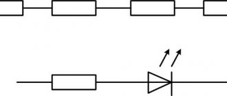
The serial connection scheme means that they are switched on in a certain sequence, one after the other. Moreover, the current strength in all of them is equal. These elements create a total stress in the area. Charges do not accumulate in the nodes of the electrical circuit, since otherwise a change in voltage and current would be observed. With a constant voltage, the current is determined by the value of the circuit resistance, so in a series circuit, the resistance changes if one load changes.
The disadvantage of this scheme is the fact that if one element fails, the others also lose the ability to function, since the circuit is broken. An example would be a garland that does not work if one bulb burns out. This is a key difference from a parallel connection, in which the elements can operate separately.
The sequential circuit assumes that, due to the single-level connection of the conductors, their resistance is equal at any point in the network. The total resistance is equal to the sum of the voltage reduction of individual network elements.
With this type of connection, the beginning of one conductor is connected to the end of another. The key feature of the connection is that all the conductors are on one wire without branches, and one electric current flows through each of them. However, the total voltage is equal to the sum of the voltages on each. You can also look at the connection from another point of view - all conductors are replaced by one equivalent resistor, and the current on it coincides with the total current that passes through all resistors. The equivalent cumulative voltage is the sum of the voltage values across each resistor. This is how the potential difference across the resistor appears.
Using a daisy chain connection is useful when you need to specifically turn a specific device on and off. For example, an electric bell can ring only when there is a connection to a voltage source and a button. The first rule states that if there is no current on at least one of the elements of the circuit, then there will be no current on the rest. Accordingly, if there is current in one conductor, it is also in the others. Another example would be a battery-powered flashlight, which only lights up if there is a battery, a working light bulb, and a button pressed.
In some cases, a sequential circuit is not practical. In an apartment where the lighting system consists of many lamps, sconces, chandeliers, there is no need to organize a scheme of this type, since there is no need to turn the lighting on and off in all rooms at the same time. For this purpose, it is better to use a parallel connection in order to be able to turn on the light in individual rooms.
Diagram and formula for series connection of conductors
A series connection is a closed circuit in which one end of the wire is in contact with the beginning of the other.
This electrical circuit may contain the following elements:
- galvanic cell, chemical source of electric current;
- battery, current source, power supply;
- connecting wires;
- key, its resistance takes either zero or infinite value;
- incandescent lamp, artificial light source;
- resistor has electrical resistance;
- fuse, performs a protective function;
- rheostat regulates current.
Electrical appliances use wires consisting of a conductive core and insulation. If the data is calculated incorrectly, insulation breakdowns occur in practice. This can result in injury and property damage.
Before connecting blocks into a circuit, it is necessary to carefully calculate the parameters of the circuit and connect them correctly using the laws of electronics.
When switched on one by one, all elements are connected one after another. The end of one wire contacts the beginning of the next in the circuit.
An elementary example of an electrical circuit with a similar connection:
- power supply, from the “plus” the wire goes to the incandescent lamp;
- from the incandescent lamp it goes to the second lamp;
- from the second lamp reaches for the key;
- the key is connected to the negative side of the power supply.
Electric current flows through all elements. If you remove one participant, the others will also stop working, because the circuit will be open.
Applications for serial connection of conductors
Thanks to Ohm's law, it became possible to use electromotive force for human purposes. Alternate connection of conductors is widely used in electrical appliances due to its peculiarity - the current value is the same in all sections of the wire. Accordingly, if the current disappears in some section, then the entire circuit becomes de-energized. This is the disadvantage of a serial connection. However, the man figured out how to turn a disadvantage into an advantage.
This property is used to protect systems from overloads by placing fuses in it.
Application examples for serial connection of conductors:
- New Year's garland;
- system overload protection;
- for voltage regulation;
- electric bell, the sound appears when the button is held (when closed);
- switches on electrical appliances.
Experienced electricians recommend using a multimeter and ammeter for service measurements. During installation work, these devices allow you to instantly obtain data.
The work of electricians involves the risk of electric shock. Regardless of the connection method, there is a risk of injury. If there is a break in the circuit, it is important to detect it in time before something irreparable happens.
We recommend reading: What are instrumentation and instrumentation systems: definition of the abbreviation, purpose
When working with a high number of volts, installers are required to wear protective clothing and shoes with thick rubber soles that protect against shock.
Alternate connections have a disadvantage. If one section is damaged, then the entire circuit is de-energized. They learned to use this property to protect networks from overloads. If one of the parameters increases sharply, the fuse trips, de-energizing the circuit. The device stops working, while remaining operational. The specialist can only carry out minor repairs by replacing the fuse. This method is used in household appliances, automobiles, and professional devices.
Photo of serial connection of conductors
Pros and cons of serial connection
The main advantages of electrical circuits made of series-connected devices are their following features:
- ease of design and construction of the circuit;
- low cost of equipment;
- the ability to connect devices designed for a lower operating voltage compared to the rated network voltage;
- performing the function of current regulation - ensures uniform loads on all devices.
However, this method of electrical circuit layout also has serious disadvantages. The main one is the unreliability of a chain of series-connected conductors. If any of the connected devices fails, the entire circuit is switched off.
In addition, the disadvantage is that the voltage decreases with an increase in the number of connected consumers. An example would be a series connection of several lamps. The more lighting fixtures connected to the power source in this way, the less bright the light they will produce.
Parallel connection
A parallel connection is a connection in which the beginnings of all conductors are connected to one point in the circuit, and their ends to another.
Points in a circuit at which several wires converge are called nodes. Sections of the chain connecting nodes to each other are called branches.
For parallel connection:
- the voltage on all conductors is the same;
- the current strength at the junction of the conductors is equal to the sum of the currents in the individual conductors;
- the reciprocal of the resistance of the entire connection is equal to the sum of the reciprocals of the resistances of the individual conductors.
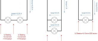
Example 3
Determine the currents and voltages of all sections of the circuit (Fig. 5), if you know:
- Rated network voltage Un = 220V;
- The filament resistance in lamps HL1 and HL2 is Rl1 = Rl2 = 122 Ohms.
- The filament resistance in the HL3 lamp is Rl3 = 153 Ohms.
Solution
We draw up an equivalent circuit for the circuit shown in Fig. 5.
1. Determine the conductivity of the entire circuit [L1, p.47] and according to table 1.8:
2. Determine the resistance of the entire circuit [L1, p.47]:
3. Determine the current strength of the circuit according to Ohm’s law:
4. Determine the currents for each circuit [L1, p.47]:
5. Let’s check that the current strength at the junction of the conductors is equal to the sum of the currents in the individual conductors:
Il1+ Il2+ Il3=Itotal=1.8+1.8+1.44=5.04=5.04 (the condition is met)
Resistance in a circuit when conductors are connected in parallel
Let's move on to the resistance. With a parallel connection, you can imagine all the conductors as one. This one conductor will clearly be larger in diameter than each of them individually. It turns out that the cross-sectional area of the conductor seems to increase with such a connection.
Resistance is calculated using the formula $R = frac{rho l}{S}$. The larger the cross section, the less resistance.
This means that the total resistance of the circuit decreases. It becomes less than the resistance of each of the conductors that are included in such an electrical circuit.
In the circuit in Figure 1 we have two identical lamps with resistances $R_1$. The total circuit resistance $R$ will be half the resistance of each lamp: $R = frac{R_1}{2}$.
The total resistance of the circuit when connecting conductors in parallel is calculated by the formula: $frac{1}{R} = frac{1}{R_1} + frac{1}{R_2} + … + frac{1}{R_n}$.
How does the total resistance of the branch change after increasing the number of conductors in the branch?
Obviously, the more conductors there are in the branch, the lower the overall resistance of the circuit will be.
Practical application of parallel connection
The load is connected in parallel when it is necessary to separately connect several consumers in one room. With a 220 V household network, this could be: a chandelier, TV, refrigerator, electric stove and many other household appliances. With this connection, the 220V voltage is not divided by the number of consumers, but is connected to the voltage source, each separately with its own switch.
Fig.2. Parallel load connection
To understand the ongoing actions with current and voltage in conductors when connecting a load, all processes are generalized into single rules, which have received the status of a law and are called the Law of Series and Parallel Connection of Conductors. One of the basic laws of the circuit section is Ohm's law. Ohm's law for parallel and series connections of conductors expresses the dependence of the current on the resistance in the section and its voltage: I=U/R - the greater the resistance, the less the current. Ohm's law parallel and series connections of conductors.
With a series connection, the total current value is distributed over each section: I = I1 = I2;
voltage is distributed over the number of load elements: U = U1 + U2 = I(R1 + R2) = IR; The resistance of the load elements in the circuit will simply add up to the total: R = R1 + R2. Parallel connection of conductors characterizes a circuit in which the voltage is equal across all loads: U = U1 = U2. The amount of current is equal to the sum of the current consumed in each load circuit with a parallel arrangement I = I1 + I2. The study of series and parallel connections of conductors and an understanding of the laws of current distribution provides the necessary basis for further study of electrical engineering and the application of this knowledge in practice.
We recommend reading: How to determine phase and zero: with an indicator screwdriver, multimeter, visually
To consolidate the material and better understand what follows, it is recommended to watch the video tutorial on serial and parallel connection of conductors
Pros and cons of parallel connection
When using parallel connection of conductors, the following set of advantages is provided:
- voltage stability on electrical appliances, regardless of their number;
- the ability to turn on or off individual sections at the right time without disrupting the operation of the entire electrical circuit;
- reliability – if one or more components fail, the electrical circuit itself continues to operate.
The disadvantage is a more complex calculation and complex circuit, the use of which increases the cost of completing the electrical network.
It is not allowed to connect devices with a rated operating voltage less than the network voltage. Parallel connection of batteries with different voltage values is associated with the flow of current into the battery with a lower value, which can cause accelerated wear of the battery.
How to measure electrical impedance
Let's connect all the parts together into a simple electrical circuit. Let's take a look at the figure below: This is a circuit with a DC power supply. Current flows through a resistor. Quite simple, right? The greater the resistance of the resistor in the circuit, the less current will be.
Simple DC circuit with resistor
at 100 ohms to limit current What happens if we add an AC power supply, an inductor, and a capacitor to an electrical circuit? Now there are two additional components in the circuit, each of which offers resistance to electrical current in its own way. Like a resistor, they both prevent the passage of electrical current while also influencing the current. If you add up the active resistance of the resistor and the active and reactance of the capacitor and inductor, you get the total electrical resistance or impedance.
In an AC circuit, a resistor, an inductor and a capacitor are connected in series
Wait! To calculate the total electrical resistance, it is not enough to simply add the active and reactive resistances. Usually, in most textbooks, an abundance of mathematical formulas begins from this point, so read on slowly.
Laws of series and parallel connection of conductors
For a detailed understanding in practice of both types of connections, we present formulas explaining the laws of these types of connections. Power calculations for parallel and series connections are different.
In a series circuit, there is the same current in all conductors:
I = I1 = I2.
According to Ohm's law, these types of conductor connections are explained differently in different cases. So, in the case of a series circuit, the voltages are equal to each other:
U1 = IR1, U2 = IR2.
In addition, the total voltage is equal to the sum of the voltages of the individual conductors:
U = U1 + U2 = I(R1 + R2) = IR.
The total resistance of an electrical circuit is calculated as the sum of the active resistances of all conductors, regardless of their number.
In the case of a parallel circuit, the total voltage of the circuit is similar to the voltage of the individual elements:
U1 = U2 = U.
And the total strength of the electric current is calculated as the sum of the currents that exist in all conductors located in parallel:
I = I1 + I2.
To ensure maximum efficiency of electrical networks, it is necessary to understand the essence of both types of connections and apply them expediently, using the laws and calculating the rationality of practical implementation.
Sample task
The lighting network of the room includes two electric lamps, the resistances of which are equal to $200 \space Ohm$ and $300 \space Ohm$. The network voltage is $120 \space V$. Determine the current in each lamp, the current in the conducting wires (that is, the current before the branching), the total resistance of the section consisting of two lamps.
It is assumed that the lamps are connected to the network in parallel. Let's write down the conditions of the problem and solve it.
Given: $R_1 = 200 \space Ohm$ $R_2 = 300 \space Ohm$ $U = 120 \space V$
$I_1 — ?$ $I_2 — ?$ $I — ?$ $R — ?$
Solution:
Let's write Ohm's law for the section of the circuit with the first lamp: $I_1 = \frac{U_1}{R_1}$.
We know the value of resistance. What about the voltage in this area? Since the lamps are connected in parallel, the voltage on each will be equal to the voltage in the entire circuit: $U_1 = U_2 = U = 120 \space V$ Then we can calculate the current in each lamp.
Current strength in the first lamp: $I_1 = \frac{U}{R_1}$, $I_1 = \frac{120 \space V}{200 \space Ohm} = 0.6 \space A$.
Current strength in the second lamp: $I_2 = \frac{U}{R_2}$, $I_2 = \frac{120 \space V}{300 \space Ohm} = 0.4 \space A$.
The current strength before the branching will be equal to the sum of the strengths of these two currents in the lamps: $I = I_1 + I_2$, $I = 0.6 \space A + 0.4 \space A = 1 \space A$.
We can determine the total resistance of the circuit in two ways.
Method No. 1 Using Ohm's law for a circuit section consisting of two parallel-connected lamps: $I = \frac{U}{R}$, $R = \frac{U}{I}$, $R = \frac{120 \space B}{1 \space A} = 120 \space Ohm$.
Method No. 2 Using the formula for calculating resistance when connecting conductors in parallel: $\frac{1}{R} = \frac{1}{R_1} + \frac{1}{R_2}$, $\frac{1}{R } = \frac{1}{200 \space Ohm} + \frac{1}{300 \space Ohm} = \frac{5}{600 \space Ohm} = \frac{1}{120 \space Ohm}$ .
Hence, $R = \frac{1}{\frac{1}{120 \space Ohm}} = 120 \space Ohm$.
When solving this problem, we made sure that the total resistance of the circuit is less than the resistance of each of the parallel-connected conductors: $R < R_1 < R_2$.
Answer: $I_1 = 0.6 \space A$, $I_2 = 0.4 \space A$, $I = 1 \space A$, $R = 120 \space Ohm$.
Mixed compound
A mixed connection of conductors, as the name suggests, can be a set of any combinations of series and parallel connections, and these connections can include both individual resistors and more complex composite sections.
The calculation of a mixed connection is based on the already known properties of serial and parallel connections. There is nothing new here: you just need to carefully divide this circuit into simpler sections connected in series or in parallel.
Let's consider an example of a mixed connection of conductors (Fig. 6).
Rice. 6. Mixed compound
Let V, Om, Om, Om, Om, Om. Let's find the current strength in the circuit and in each of the resistors.
Our circuit consists of two sections connected in series and the resistance of the section is Ohm.
The section is a parallel connection: two resistors connected in series and connected in parallel to the resistor Then:
Ohm.
Circuit resistance:
Ohm.
Now we find the current strength in the circuit:
A.
To find the current in each resistor, let's calculate the voltage in both sections:
B;
B.
(Note in passing that the sum of these voltages is equal to V, i.e., the voltage in the circuit, as it should be with a series connection.)
Both resistors are energized therefore:
A;
A.
(In total we have A, as it should be with a parallel connection.)
The current strength in the resistors is the same, since they are connected in series:
A.
Therefore, current A flows through the resistor.
Methods for connecting resistors, solving the problem of mixed connection of conductors: video
Parallel connection of elements in an electrical circuit
Which connection of conductors is called parallel?
Let's assemble an electrical circuit with such a connection. The circuit will consist of a current source, a key and two electric lamps. in parallel to the circuit (Figure 1).
Figure 1. Electrical circuit with parallel connection of electric lamps
The diagram of this electrical circuit is shown in Figure 2.
Figure 2. Electrical circuit diagram with parallel connection of electric lamps
The diagram shows two points A and B. Important point:
In a parallel connection, all the conductors included in it are connected at one end to point A , and at the other end to another point B.
So we can connect several more lamps or a number of other electricity consumers. , all the patterns that we will consider below will be valid for any number of conductors connected in parallel to the circuit between points A and B.
Examples of calculations
As practical examples, we can consider several options for calculating circuit parameters in different connection schemes.
For resistors
The simplest example of a calculation would be a chain of two resistances - 10 Ohms and 100 Ohms, connected in a chain. 12 volts are applied to the circuit.
A series circuit of two resistors.
First you need to find Rtotal, it is equal to the sum of R1 and R2. Rtot=100+10=110 Ohm. Hence the current in the circuit is I=U/R=12/110=0.109 amperes. The drop on each element can be calculated based on the equalities U1=I*R1 and U2=I*R2. Hence U1=1.1 V, and U2=10.9 V. Obviously, U1/U2=R1/R2. The first element will dissipate power P1=U1*I=1.1*0.109=0.12 watts (for practice, a standard component of 0.125 watts is suitable), and the second one will dissipate P2=U2*I=10.9*0.109=1 .19 watts (for practical implementation you will need a two-watt power supply).
If you connect these same two resistors in parallel and apply the same voltage, the parameters will be distributed differently.
Connecting elements in parallel.
We recommend reading: Direct electric current power
First you need to determine Rtot=R1*R2/(R1+R2)=110*10/(110+10)=1100/120=9.17 Ohm (less than the smallest value of 10 Ohm). The total current will be I=U/Rtotal=12/9.17=1.31 amperes. Through the first element I1=U/R1=12/10=1.2 amperes will flow, through the second I2=U/R2=12/100=0.12. Obviously, I1+I2=I (taking into account rounding errors). The power required is:
- P1=I1*U=1.2*12=14.2 watts;
- P2=I2*U=0.12*12=1.42 watts.
If there is a mixed connection of elements, you must first convert the circuit to the same type - parallel or serial. Let there be a diagram of the following type.
Conversion of a mixed circuit.
In this case, it is convenient to replace the parallel assembly of R1 and R2 with a resistor with an equivalent resistance of R12, and R3 and R4 with R34. First, R12=R1*R2/(R1+R2)=9.17 Ohm is found. Using the same method, R34=150*5/(150+5)=4.8 Ohm is calculated. Then the total resistance of the equivalent circuit will be equal to R12+R34=9.17+4.8=13.97 Ohms.
Hence I=U/R=12/13.97=0.86 amperes. On the “garland” R1R2 the drop is U12=I*R12=0.86*9.17=7.87 volts, and on R3R4 the drop will be U34=I*R34=0.86*4.8=4.13 volts. Next, we need to return to the original circuit and consider separately the section of the R1R2 circuit with the found parameters.
Section of the circuit containing R1 and R2.
Hence I1=U/R1=7.87/10=0.787 amperes, I2=U/R2=7.87/100=0.0787 amperes. By power – P1=U*I1=7.87*0.787=6.2 watts, P2= U*I2=7.87*0.0787=0.62 watts.
The section containing the R3R4 elements is calculated in the same way.
Series and parallel connection of batteries
For light bulbs
Using exactly the same methods, you can calculate the parameters of a circuit consisting of two or more incandescent light bulbs - in practice, this situation can be encountered more often. But there are two problems. The first of them is that the filament resistance is not indicated on the light bulbs and in the technical data on them. It will have to be recalculated based on the rated voltage and power. Since P=U*I, and I=U*R, then P=U2/R, and R=U2/P. So, for a 10-watt, 12-volt light bulb, the filament resistance will be 122/10=144/10=14.4 ohms. You can calculate the characteristics of a circuit for two light bulbs connected in series and in parallel.
Connecting lamps in a chain.
In the first case, the current flowing through each lamp will be common and equal to I=U/Rtotal=12/(14.4+14.4)=12/28.8=0.42 A. U/2 will drop at each lamp =6 volts. And the electrical power of each element will be 0.42 * 6 = 2.5 W, which is ¼ of the nominal value of the light bulb. This decrease was due to a twofold decrease in current and a twofold decrease in voltage. Naturally, the light bulbs will not glow at full intensity. To bring the brightness of the glow to normal, you will have to double the voltage, which will simultaneously double the current.
Connecting two light bulbs in parallel.
If the light bulbs are connected in parallel, then the nominal level of 12 volts will drop on each of them. I=U/R= 12/14.4=0.83 A will flow through each element, and the power on each light bulb will be equal to P=U*I=12*0.83=10 watts, that is, the nominal value. And each thread will shine at full intensity. But the entire circuit will consume 20 watts and 0.83 * 2 = 1.66 A will flow through it, which is twice the value for one lamp.
There is a second problem. In general, resistance depends on current and applied voltage, but for incandescent lamps this dependence is pronounced. The thread in the cold state has a low resistance, and reaches the nominal value when warmed up in the nominal mode. Therefore, the above calculations are correct only for a standard voltage of 12 volts. Under other conditions, the characteristics of the lamp will be different, and, by and large, the calculation for the parallel case is inaccurate - the filament resistance will be less than 14.4 Ohms. But this property allows the lamp to be used as a current stabilizer - as its value increases, the filament will heat up, the resistance will increase, and the current will drop to approximately the previous level. When it decreases, the reverse process will occur with a decrease in the filament level of the light bulb.
What is resistance
Current flowing through wires and various radio components wastes its energy. This phenomenon is quantitatively expressed by the magnitude of the resistance. In electrical engineering, it is divided into active and reactive resistance. In the first case, when a current passes, part of its energy is converted into a thermal form, and sometimes into others (for example, it manifests itself in chemical reactions). The value of active resistance depends on the frequency of alternating electric current and increases with its increase.
The second type of resistance has a more complex nature and occurs when a consumer of electricity is turned on or off in an AC or DC network. In a circuit with reactance, the energy of the electric current is partially converted into another form, and then transferred back, that is, a periodic oscillatory process is observed. Circuit impedance includes active and reactive types, which are taken into account according to special rules.