Today's post is about rectifiers.
.
What are they and what do they eat them with? Well, first of all, let's start with the fact that most electronic devices consume DC electrical energy for their operation. DC sources can be various galvanic cells (batteries), accumulators, thermoelectric generators, DC electric machines and rectifiers. The most common source of direct current is a rectifier
- a device that converts alternating current into direct current.
To assemble a radio-electronic device, you can pre-make a DIY KIT kit using the link.
As a rule, rectifiers consist of power elements
(most often diodes),
a transformer
(for converting alternating voltage and electrical isolation between the input and output circuits of the rectifier) and a smoothing filter (reduces voltage ripple across the load). Depending on the number of phases of the power supply system, single-phase and three-phase rectifiers are distinguished.
Germanium and silicon diodes are used as power elements of rectifiers. Silicon diodes have almost completely replaced germanium diodes. The only drawback of silicon diodes compared to germanium diodes is a high forward voltage drop of the order of 0.6...0.8 V instead of 0.1...0.3 V.
The general disadvantages of most high-power rectifier diodes are the long process of resorption of minority charge carriers and the long recovery time of the reverse resistance. This becomes especially noticeable when rectangular voltage is rectified with an alternating current frequency above 1 kHz and manifests itself in a decrease in the average value of the rectified voltage, an increase in ripple, and a decrease in rectifier efficiency.
Currently, Schottky diodes (diodes based on contact between a metal and a semiconductor) are becoming increasingly widespread. These diodes do not have the phenomenon of accumulation and resorption of minority charge carriers, which allows them to operate at frequencies of hundreds of kilohertz. In addition, their forward voltage drop is approximately half that of conventional silicon diodes.
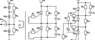
Series and parallel connections of diodes.
If for the rectifier circuit it is impossible to select the desired type of diode in accordance with the specified value of the reverse voltage or forward current, then two or more diodes of the same type with lower parameter values are used, including these diodes in series or in parallel.
Parallel connection of diodes
Parallel connection of diodes
When parallel connection of diodes
due to possible scattering of parameters, their currents will be different. One of these currents may exceed the maximum permissible value, which will lead to failure of first one and then the other diode. A more uniform distribution of current between parallel-connected diodes is achieved by connecting resistors Rd of the same value in series with each of them. The resistance of the resistors Rd should be 5...10 times greater than the resistance of the diode in the forward direction. In powerful rectifier devices, inductive current equalizers are used for the same purpose.
Calculation of parallel connection of diodes
To start the calculation, you need to determine the required number of parallel-connected diodes
, based on the fact that the current passing through one diode should not exceed the maximum permissible current value for a given type of diode, then the number of parallel-connected diodes will be equal to
, where Im is the maximum current value passing through the diodes, kT is the current load factor ( can take values from 0.5 to 0.8), Inp is the average forward current for a given type of diode.
For fractional values of the estimated number of diodes, rounding is carried out upward.
value of additional resistors
is determined by the formula
, where n is the number of rectifier diodes, Unp.cp is the constant forward voltage for a given type of diode.
The calculated resistance of additional resistors is rounded to the nearest standard resistance.
Example of calculation of parallel connection of diodes
Calculate a rectifier circuit that allows you to obtain a rectified current I rectified = 550 mA if D226B diodes are used.
Since the average forward current of the D226B diode Ipr. av = 300 mA, then it is necessary to use several parallel-connected diodes with additional resistors. Let's calculate the number of parallel-connected diodes, take kT = 0.8
Let's take n = 3.
Let's find the value of the resistance of additional resistors
Let's choose a resistor from the standard range of resistances E24 (± 5%) Rext = 6.2 Ohm
Online calculator for calculating the connection of rectifier diodes
Series connection of diodes
Series connection of diodes
To ensure that the selected type of diode can operate in a rectifier circuit with a reverse voltage exceeding its maximum permissible value, diodes of the same type should be connected in series
. If the parameters do not match, then one of the diodes is under significantly higher voltage than the other. This can lead to breakdown of one and then another diode. Equalization of the reverse voltage on series-connected diodes is achieved by shunting each of the diodes with a resistor Rsh. The current flowing through these resistors should be 5...10 times greater than the maximum possible reverse current of the diodes. In powerful high-voltage rectifier devices, for the same purpose, diodes are shunted with capacitors Сш or an RC circuit.
Calculation of series connection of diodes
To start the calculation, you need to determine the number of diodes connected in series
, based on the fact that the voltage drop on each individual diode should not exceed the amplitude voltage value, then the number of diodes connected in series will be equal to
, where
Um is the amplitude value of the voltage passing through the diode, kH is the voltage load factor (can take values from 0. 5 to 0.8), Uobp max - maximum permissible reverse voltage of the diode.
For fractional values of the estimated number of diodes, rounding is carried out upward.
Shunt resistor resistance values
is determined by the formula
, where
Iobp max is the maximum permissible reverse current of the diode at the maximum temperature.
An example of calculating a series connection of diodes
Calculate the rectifier circuit for a voltage with an amplitude value of 700V using D226B diodes.
Since the maximum permissible reverse voltage of the diode is Urev.max = 300V, for rectification it is necessary to use a chain of series-connected diodes with shunt resistors. Let's calculate the number of series diodes, take kH = 0.7
Let's take n = 4
Let's find the value of the resistance of the shunt resistors
Let's choose a resistor from the standard range of resistances E24 (± 5%) Rsh = 1 MOhm
The inclusion of additional and shunt resistors is inevitably associated with an increase in power losses and a decrease in the efficiency of the rectifier circuit.
Online calculator for calculating the connection of rectifier diodes
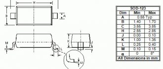
Marking of zener diodes
In order to find out the stabilization voltage of the Soviet zener diode, we need a reference book. For example, in the photo below there is a Soviet zener diode D814V:
We look for parameters for it in online directories on the Internet. As you can see, its stabilization voltage at room temperature is approximately 10 Volts.
Foreign zener diodes are marked more easily. If you look closely, you can see a simple inscription:
5V1 - this means the stabilization voltage of this zener diode is 5.1 Volts. Much easier, right?
The cathode of foreign zener diodes is marked mainly with a black stripe
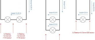
Basic rectification schemes and their comparative characteristics.
Amateur radio and household radio-electronic equipment is powered only from a single-phase alternating current network. Therefore, single-phase rectification circuits are discussed below.
Basic single-phase voltage rectification circuits: half-wave, full-wave with midpoint, full-wave bridge, voltage multiplier circuit. In practice, complex rectification circuits are also used, formed from two or more simple circuits by combining them. It is advisable to use combined rectification circuits only with a constant load across all output circuits; otherwise, mutual influence of the power supply output channels will be observed.
Half-wave rectification circuit
Single-phase half-wave rectification circuit
Can work both without an input transformer and with a transformer. Current flows through the diode VD only when the polarity of the corresponding half-cycle of the mains voltage will cause the diode to open. The diode current at any time is simultaneously the current of the secondary winding of the transformer and the load current. With an active load, it takes the form of unipolar pulses with a duration equal to half the network period. During the other half-cycle of the supply voltage Uc, the diode VD is in the closed state. When designing a transformer for half-wave rectification circuits, the magnetization of the magnetic core should be taken into account, therefore the overall design power of the transformer should be increased to the value Pr = (3.36...3.5) Po.
Single-phase half-wave rectification circuit
The advantage of the circuit is its simplicity, minimum number of valves.
The disadvantages of a half-wave rectification circuit are the large ripple value of the rectified voltage and the low ripple frequency, equal to the network frequency; poor transformer use; high reverse voltage on the diode (3.14 times the rectified voltage); large current pulse through the diode.
A half-wave rectification circuit is used for low output power (1...3 W) and low requirements for rectified voltage ripple. Most often, such a rectification circuit is used in combination with a single-ended voltage converter and a capacitive filter to convert a low-voltage DC supply voltage to a high-voltage one.
Full-wave rectification circuit with midpoint
Single-phase full-wave rectification circuit with midpoint
is a combination of two parallel-connected half-wave circuits operating alternately on one common load resistance. The circuit can operate from an alternating current network only if there is an input transformer that has a tap from the center point in the secondary winding. The voltage Uc supplied to the primary winding is transformed into secondary ones in such a way that one of them (for example, U'v) is opening for diode VD1, and the other (U''v) is closing for diode VD2. A current pulse similar to the pulse of a half-wave rectification circuit flows through the diode VD1 and the load resistance Rn during half the period of the mains voltage. In the next half-cycle, the polarity of the voltage on the half-windings is reversed, diode VD1 closes, and VD2 opens. In this case, the current pulse will flow through the diode VD2 and the load resistance Rн, that is, the current through the load flows during each half-cycle in one direction.
Single-phase full-wave rectification circuit with a midpoint
Since the currents in the secondary half-windings of the transformer flow alternately in opposite directions, there is no magnetization of the magnetic circuit.
The ripple frequency of the rectified voltage is equal to twice the network frequency.
A full-wave rectification circuit with a midpoint has a number of advantages over a single-half-wave rectification circuit: with the same output power, the dimensions and weight of the transformer are smaller (due to the absence of magnetization); the amplitude of the current through the rectifier diodes is half as large; the ripple frequency of the rectified voltage is twice as high. Compared to a bridge, a full-wave rectification circuit with a midpoint has a smaller number of diodes in the arm and, accordingly, a higher efficiency. Both diodes can be installed on a common radiator without electrical insulation.
The disadvantages of the circuit are the presence of a transformer at the input; worse use of transformer windings compared to other full-wave rectification circuits (current flows through each half-winding only for half a period); high reverse voltage on diodes; the possibility of ripples appearing at the output of the circuit at the network frequency due to the asymmetry of the arms.
The circuit is universal in application, however, due to the high reverse voltage on the diodes, it is rarely used for rectifying high-voltage voltage.
Bridge rectifier circuit
Single-phase bridge full-wave rectification circuit
is a rectifier made of four diodes connected in a bridge circuit.
One diagonal of the bridge contains the secondary winding of the transformer, and the other diagonal contains the load resistance. The mains voltage can be connected to the bridge rectifier directly. bridge full-wave rectification circuit
During one half-cycle of the mains voltage, the load current flows through two series-connected diodes, for example VD1 and VD4, during the next half-cycle through two other diodes (VD2 and VD3). In the presence of a transformer, current flows through the secondary winding during each half-cycle, but in opposite directions, so magnetization of the magnetic circuit is eliminated.
The advantages of a bridge rectification circuit over a circuit with a midpoint are lower overall transformer power; half the reverse voltage on a closed diode; the circuit can operate without an input transformer; if there is a tap from part of the secondary winding, it is possible to obtain two output voltages.
The disadvantages of the circuit are a large number of diodes, which reduces its efficiency; it is impossible to install all four diodes on a common radiator without electrical insulation.
The bridge rectification circuit is universal in application. However, it is rarely used to rectify relatively low voltages, since at output voltages commensurate with the voltage drop across the diodes, the efficiency of the rectifier sharply decreases.
How to check zener diode
How to check the zener diode? Yes, just like a diode! You can see how to check the diode in this article. Let's check our zener diode. We put the multimeter on the continuity test and attach the red probe to the anode, and the black probe to the cathode. The multimeter should show the voltage drop of the forward PN junction.
We swap the probes and see one. This means that our zener diode is in full combat readiness.
Well, it's time for experiments. In the circuits, a zener diode is connected in series with a resistor:
where Uin is the input voltage, Uout.st. — output stabilized voltage
If we look closely at the diagram, we get nothing more than a voltage divider. Everything here is elementary and simple:
Uin=Uout.stab +Uresistor
Or in words: the input voltage is equal to the sum of the voltages on the zener diode and the resistor.
This circuit is called a parametric stabilizer on one zener diode. The calculation of this stabilizer is beyond the scope of this article, but for those interested, Google
So, let's put together the circuit. We took a resistor with a nominal value of 1.5 Kilohms and a zener diode with a stabilization voltage of 5.1 Volts. On the left we connect the power supply, and on the right we measure the resulting voltage with a multimeter:
Now we carefully monitor the readings of the multimeter and power supply:
So, while everything is clear, let’s add more tension... Oops! Our input voltage is 5.5 Volts, and our output voltage is 5.13 Volts! Since the stabilization voltage of the zener diode is 5.1 Volts, as we can see, it stabilizes perfectly.
Let's add some more volts. The input voltage is 9 Volts, and the zener diode is 5.17 Volts! Amazing!
We also add... The input voltage is 20 Volts, and the output, as if nothing had happened, is 5.2 Volts! 0.1 Volt is a very small error, it can even be neglected in some cases.
Comparative characteristics of the parameters of rectifier circuits
Comparative characteristics of the parameters of rectifier circuits
is presented in a table that contains some information about the parameters of currents and voltages in rectifier circuits. In the table, the base voltage is considered to be the constant voltage U0 at the rectifier output
| Determined value and its designation | Half-wave rectification circuit | Full-wave circuit with midpoint | Bridge rectification circuit |
| DC component of rectified voltage, U0 | 1 | 1 | 1 |
| Effective value of voltage on the phase of the secondary winding of the transformer, UB | 2.22 U0 | 1.11 U0 | 1.11 U0 |
| The largest (amplitude) value of the reverse voltage applied to one diode, Urev | 3.14 U0 | 3.14 U0 | 1.57 U0 |
| Amplitude of the alternating component of the rectified voltage, Up max | 1.57 U0 | 0.67 U0 | 0.67 U0 |
| Load current, I0 | 1 | 1 | 1 |
| Effective current value through one diode, IB | 1.57 I0 | 0.785 I0 | 0.785 I0 |
| Maximum (amplitude) value of current through one diode, Imax | 3.14 I0 | 1.57 I0 | 1.57 I0 |