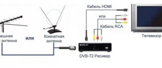
To reliably receive digital terrestrial signals and display television channels, you need the right antenna. The best way is to buy a factory design with an amplifier. This way you will be able to catch up to 30 terrestrial channels of the DVB-T2 standard on the territory of the Russian Federation, even if the repeater is very remote.
An alternative is a homemade antenna. It is possible to produce more than 10 design options that can accept “digital”. One of the designs that provides a good signal is the Kharchenko antenna.
In the circle of radio amateurs it is also called “biquadrat” (double square), “eight”, “diamond-shaped”, “double diamond”, “double zigzag”, “zigzag”.
In order for the biquad to work at the highest level, you need to make an antenna in accordance with the wavelength that is transmitted by the digital repeater. Therefore, it is necessary to make small calculations, since the quality of DVB-T2 signal reception depends on this.
The concept of the Kharchenko antenna
This is a zigzag antenna that looks like two squares fastened together. Each vibrator angle is 90°.
Signal reception at a sufficient level is ensured due to the design, compliance with the values, and wire length. It is for this reason that it is important to calculate the antenna for digital terrestrial television as accurately as possible. It is necessary to calculate the length of the conductor.
The biquad antenna can be used not only for receiving digital TV, but also as an amplifier for other types of signals. You can calculate the design in such a way that it turns out to strengthen the signal of mobile communications, mobile Internet (3G, 4G), Wi-Fi signal. In each case, when calculating, you will need to substitute different values into the formula.
The diamond-shaped antenna, in addition to its wide range of applications, has the following advantages:
- high gain;
- wide scope of application (described in a paragraph earlier);
- broadband – capable of receiving meter and decimeter waves simultaneously, which means you can tune in to digital and analog channels at once;
- ease and low cost of production. Even a beginner can make a Kharchenko antenna with his own hands for digital TV. You just need to make a simple calculation for the specific needs, bend a piece of copper wire according to the template and connect the antenna cable to the structure.
Types of television antennas for digital TV
A digital antenna differs from a conventional one not only in its design, but also in its ability to perceive signals. A device for television of a new format receives waves of a completely different frequency, while a traditional antenna picks up the frequency of familiar standards.
IMPORTANT ! A ton of new channels of improved quality are transmitted to your TV via a digital signal. This format is relevant for owners of widescreen TVs, which are capable of transmitting clear color and perfect image graphics. In order to choose the right antenna or make it yourself, you need to know what types of structures are suitable for using television of the new format.
| Photo | Antenna type | Description |
| Professional devices | ||
| Funke DCRS.1760/1−69 | This is a combined device designed to receive all digital waves. The body of the device is made of aluminum coated with a golden alloy. The design is equipped with an amplifier with parameters from 5 to 15 Db. Has three outputs for connection. The antenna is installed outside. | |
| Funke DCRS.1753/1−69 | Antenna model for digital TV, similar to the previous design. It has a similar structure, two outputs for connection and an amplifier with a range of 3−15 Db. | |
| Logo P-14 | A combined design that receives signals from all types of waves. The device is intended for installation outside of multi-storey buildings. The basis of the design is ferrous metal, it is considered strong and durable. | |
| DMV Funke BM4591/21−69 | The aluminum construction with gold alloy is an excellent device for high-quality viewing of digital broadcasts. The installation has 91 components, including amplification with a parameter of 16.7 Db. | |
| Room designs | ||
| Delta | An antenna intended for indoor use is connected directly to the TV socket. The device picks up UHF waves with a frequency of 470−790 MHz. Capable of receiving from 21 to 60 TV stations. | |
| Delta DIGITAL 5B | Suitable exclusively for DVB T and DVB T2 waves. An amplifier is included with the cable. | |
| Uralochka | The design is designed to receive digital television waves and analog TV. It has a long cable, so it allows you to place the structure in any convenient place. | |
| Outdoor models | ||
| UHF antenna | The design is designed to receive analogue waves and is capable of configuring from 21 to 69 channels. Has built-in amplification of 8.5−11 Db. | |
| Delta N111A.02F | Designed to receive a signal of horizontal polarization of frequencies in the range 470−790 Db. The installation is equipped with a splitter and amplifier. | |
When choosing an antenna for a digital TV, be sure to pay attention to the design features, as well as the presence of an installation manual. You can also design a suitable version of the “receiver” yourself.
Making a biquad antenna with your own hands
The time required for assembling the structure is a maximum of 1 hour. If you know how to handle tools, and have at least some skill in assembling other structures, you can do it in 30-40 minutes. Elements for the structure can often be found at home. As a last resort, the components can be easily purchased at the radio market or at a hardware store.
Materials and tools
Main list:
- copper wire with a cross-section of 1.5-5 mm (it is better not to use an aluminum conductor or other material, since it is difficult to solder on them, and these places directly affect signal loss);
- coaxial cable with a resistance of 75 Ohms (for digital television broadcasting), 3-5 m long (depending on the location of the antenna, the further the installation is from the TV, the longer the cable will be);
- pliers to bend the wire in the right places if the material is thick and making bends with your hands is problematic;
- material for cleaning the places to which the cable will be connected (file or sandpaper);
- tape measure, centimeter or ruler to accurately measure the length of the element;
- soldering iron, materials for easy and high-quality soldering (rosin, tin);
- F-plug, which is mounted on the second end of the cable and inserted into the antenna connector of the TV.
If the antenna is installed on the roof of a private house, you may need a long wooden, plastic or even metal bar. It will serve as a matcha on which Kharchenko’s design will be fixed.
To protect connections when installed outside buildings, it is better to protect the antenna from moisture. The easiest way to wrap the joint and solder joints is with electrical tape. This option is simple, since the electrical tape can be torn off at any time and access to the connections. An option that will reliably close the connections (but tightly) is to fill them with epoxy resin, silicone sealant, hot melt adhesive or varnish.
Video
Manual calculation
You don’t have to calculate the antenna for T2, but then you are not sure that you will be able to watch digital channels at all. Therefore, you need to have accurate data; this will allow you to catch at least 20 channels in your region. Thirty channels (the third multiplex) can only be watched in Moscow, the region and Crimea.
Let's perform the calculation using the example of the city of St. Petersburg.
- First you should find out the frequencies of the channel numbers that are broadcast in the region. Since the biquad antenna must operate in both frequency ranges, you need to find out the channel frequency of the first and second multiplex. Based on the parameters of the repeaters on the TsETV map, the first multiplex (TVK 35) broadcasts at a frequency of 586 MHz, and the second operates at a frequency of 666 MHz (TVK 45).
Using the same map you can find out your frequencies yourself. Enter your exact address in the search bar and click on your home on the map.
- Determine the average value. This will make it possible to make the antenna in an intermediate design and catch the radio signal from both multiplexes at once. We calculate the arithmetic average: (586+666)/2=626 MHz. The value will be used in further calculations.
We calculate the length using the formula: λ = c/F, where
- λ is the desired wavelength;
- C – speed of light (3*108 m/s, which is equal to 300 s);
- F – average frequency determined earlier (626 MHz).
If we substitute the available values into the formula, we get the following:
λ = 300/626 ≈ 0.4792 m ≈ 47.92 cm.
This is a figure that is equal to the length of the copper conductor to make one diamond.
In practice, when making a “biquadrat”, such dimensions can become very large. It is allowed to take a smaller value, exactly two or four times.
We have:
- λ = 47.92 cm/2 = 23.96 cm;
- or λ = 47.92 cm/4 = 11.98 cm.
Now it’s worth calculating the length of each side of the rhombus. We will use the original value of 47.92 cm.
- This means that the side will be equal to L = 47.92/4 = 11.98 cm ≈ 12 cm.
- The total length required to bend the entire antenna (two diamonds) of wire is 47.92*2 = 95.84 cm ≈ 96 cm.
Kharchenko antenna calculator
Instead of manual calculations, you can find out the most accurate dimensions of a digital antenna using the online calculator below. All you need to do is enter the average frequency in the first field of the calculator. Next, click on the “Calculate” button and the calculator will immediately display the final parameters. The advantage of the calculator is that it performs a full calculation, and not just determining the size of the outer side of the vibrator.
All dimensions are indicated in millimeters. The required values are indicated on the left in the figure.
Manufacturing
- On the wire, starting at one end, make 8 equal marks with a marker, with the same distance between each. The distance is equal to the length of the side, calculated earlier - 12 cm.
The last mark can be made a little further (for example, 13 cm), exactly, as well as leaving 1 cm before the first mark. At the end and beginning of the conductor there will be a small “shoot” that can be bent. It will be easier to join and solder to it. You will see an example of the process in the third image below.
- Consistently bend the wire along the marks until you get a “double square”.
- If you previously left small “extra” sections of copper wire, then bend them down, perpendicular to the entire structure. Make sure that there is no short circuit between one corner and another.
- Carefully strip the free ends of the wire and the adjacent solid corner. Use sandpaper or a file. Connect the ends together by winding them with thin copper wire.
- Perform final fixation through soldering.
- Remove approximately 2 cm of the cable's top insulation. Twist the shielding layer. Also remove some of the inner insulation that covers the center copper core. If possible, also strip the cable core and shield to make soldering easier. Solder the core to one center corner and attach the shield to the other fold. Do not allow the bends to close, otherwise the biquad will not work.
To prevent the cable from wobbling, thereby “losing” the connection, secure it to one of the adjacent sides with a plastic clamp or electrical tape. The first option is preferable.
Cable fixation - Cover the soldered areas with insulating agent. For example, varnish, silicone, hot melt adhesive, epoxy. As a last resort, wrap it with electrical tape.
Execution options (photo)
Plug installation
The antenna is connected to the television receiver using an adapter (plug). The part is mounted on the second free end of the antenna wire.
The adapter consists of two parts - the connector itself and the plug. The latter must be unscrewed before installation on the cable, and then screwed back in.
- Remove 10-12 mm of the top PVC layer of the cable. Cut the material carefully so as not to cut the inner insulating layer.
- Bend the entire screen (braid with foil layer, if any) back.
- Strip the cable from the internal insulation until approximately 2 mm of material remains.
- Screw the F-connector onto the cable on top of the screen. It is necessary to screw in until a small part of the central insulation enters the connector and the cable core protrudes from the connector. If putting on the connector is difficult, you can carefully clamp the part with pliers and continue screwing. You should not squeeze the connector too hard, as often the metal is not of the best quality and can crack.
- Screw the F adapter into the connector and insert the cable into the antenna socket (“RF IN”, “ANT IN”) on the rear panel of the TV. If the TV is hung on the wall and there is practically no free space behind it, then it would be wiser to use a corner adapter rather than a straight one.
One evening, wanting to calculate whether the Inv V would fit into my small garden at 80 meters, not finding the calculator in its usual place, on the shelf on the left, I typed “online calculator” into the search engine. And imagine my surprise when in line number 38 I saw “Online wire antenna calculator”! Well, I already translated it into English, it was slightly different, but the essence did not change. Of course, I went there, I think many people have already been to this site, but for me it was a discovery. I, being someone who understood how this is done, immediately “stole” it to my local machine. By the way, this does not threaten the performance of this calculator in any way, unless you start having trouble sleeping due to remorse over copyright infringement. But since there is ordinary arithmetic and physics, “charged” into a script to work on the client-server principle, I think that after my rework and indication of the original source of the idea, there can be no complaints even about my site. Especially for use on a local machine. In a word, here is the source https://www.ccdxc.org/ant_calc.htm, and here is my version, simpler and in the metric system. The comments are also creatively redesigned in the style of my site.
The calculator for short-wave wire antennas is not an invention and will not save you from the need to measure the calculated meters in wire, where the error may be much greater than in the calculator. Nevertheless, the calculation of the length for the middle of the range is carried out with more than sufficient accuracy. The dimensions of not only the horizontal canvases are taken into account, but also the lengths of the inclined rays and their projection onto the ground (whether it will fit or not fit into my garden :-). Along the way, explanations are given that will help non-radio engineers better understand the physics of antenna operation. Calculated frequencies from 1.8 to 30 MHz.
A simple formula for half-wave dipoles and Inverted Vee antennas fed from the middle of the arm: 142.65 ÷ frequency (MHz) = length (meters). Do not forget about the capacitive “end effect” (shortening factor), the correction of which is already contained in the formula. And the Inverted Vee antenna will be 2-5% shorter depending on the angle between the horizontal and the antenna arms.
| Standard half-wave dipole | Half-wave Inverted Vee dipole |
The resistance of a half-wave dipole is approximately 76 Ohms, which makes it possible to power them directly with a 75 Ohm cable; when using a 50 Ohm cable, you need to use either a tuner or a transformer (preferably with a balun). Inverted Vi, in which the ends (voltage antinodes) are much closer to the ground, and the resistance is closer to 50 Ohms, so such antennas can be fed directly with a cable with a characteristic impedance of 50 Ohms. The balun is still highly desirable.
The simplified formula for calculating the length of the wave frames is as follows: 306.3 ÷ frequency (MHz) = length (in meters).
| Full size square frame | Full size triangular frame |
The dimensions of the wave frames are, of course, larger than those of half-wave dipole antennas. But the signal levels from them are also greater, and the level of local electrical interference is less. Hence two comments. 1. It must be said that the characteristic impedance of the wave loop (triangle or square, it doesn’t matter) is in the range of 100-120 ohms. Unfortunately, I have met people who were looking to exchange a 100 ohm coaxial cable for a similar length 75 ohm. Don't do this. Read more and you will always find a solution. If you read the literature, you will see that frames can be powered for cases of horizontal (bottom) and vertical (side) polarization. It is possible to get a slight advantage for the low frequency ranges. 2. If you cannot raise the LOOP antenna to the required height, do not be discouraged: every cloud has a silver lining. 1-3 dB increase on the side where your delta (square) is inclined. Well, at the end there is a joke from the authors “... even a crummy antenna is better than no antenna!” I agree 100%
Antenna setup
The assembled antenna according to the instructions above can already pick up DVB-T2 channels.
- After installing the Kharchenko device on the street or inside an apartment or house, set up digital channels on your TV. You can either immediately perform an automatic channel search or check the signal through the manual tuning menu.
- If the auto search does not produce results, then you first need to make sure that the signal is even reaching the TV. Go to manual search on your TV and look at the signal strength scale. Sometimes called "Signal Quality".
To see at least some result, if there is one, you need to select the TVK number (we found out earlier on the interactive TCETV map). If a random channel is selected, then there will most likely be no broadcast on its frequency in your area, and therefore the signal will not appear.
How and where you need to go to see the necessary sections and settings, read the previous link. If the indicator is completely zero, then the problem is clearly in the antenna, cable, or connections. If all calculations are followed, it is most likely that the reason lies in the connections. There may be a short in the central part of the antenna. It is also possible that the antenna receiver may be placed very poorly. If it is located inside the apartment away from the window, then the signal may simply not reach the antenna. At a minimum, it is better to place the structure near a window or on a balcony. - If there is a signal, but the scale shows a weak value, then more precise adjustment is required. Try playing with the antenna, placing it closer to the window. Slowly rotate the receiver in the horizontal and vertical plane. At the same time, look at the scale in the TV settings. If the value changes, then experimentally you can achieve the highest TV signal level. When the maximum signal is reached, securely mount the antenna in the best position and perform the adjustment again.
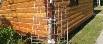
- If you can’t achieve an acceptable television signal level, take the antenna outside. The best placement option is as high as possible and when there are no obstacles to signal reception. The obstacles are dense, tall house buildings and hills.
You can strengthen the antenna if you equip it with a reflector.
Recommendations for antenna placement to achieve the best image
Making an antenna with your own hands and installing it is half the success. To obtain a high-quality image, it is necessary to correctly position and deploy the structure. Often, digital television antennas are directed to the nearest substation, which distributes the signal. You need to roughly calculate which side your TV tower is located on. Consider ways to install an antenna mast on the roof of a house. It is best to turn the designed antenna sideways towards electromagnetic waves, thus, according to experts, digital format channels will be shown clearly without snow and unnecessary noise.
NOTE! The antenna can also pick up analog television channels, however, such programs cannot be tuned perfectly. If you have any questions about the topic of the article, be sure to ask them in the comments. Gadgets-reviews editorial specialists will answer you as soon as possible.
Making a reflector
The reflector is a metal base located behind the main structure. It will reflect the signal to the main receiving element, thereby amplifying it.
What can a reflector for a “Kharchenko biquadrat” be made from:
- solid sheet of metal;
- an electrical board, one side of which is covered with a solid copper layer;
- any durable surface on which a layer of foil is glued on the reflective side;
- a grid of metal conductors (similar to an animal cage).
In the photo below, the reflector is represented by a piece of metal from the computer system unit case.
When installing a “double diamond”, the distance from the reflector to the main structure should be taken into account. The value should be equal to the seventh part (1/7) of the wavelength, that is, seven times less than one side of the rhombus.
The size of the reflector is maintained so as to completely cover the antenna area with a margin. You can take a sheet 20% larger than the area of the “bisquare”.
There should also be no short circuit between the reflector and the biquadrate. Therefore, the mounting legs must be made of plastic or other non-conductive material. A good solution would be to mount it on legs made of thin plastic pipe.
The example below shows a mount using a marker shell and a clamp. The inner ink rod is removed and a clamp is threaded through the shell.
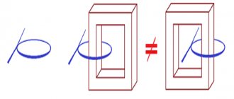
Evolution
The antenna, invented by Kharchenko, is a double square made of thick copper wire. The squares are connected to each other with open corners, and at this point the television cable is connected to them. To improve directionality, a grille made of conductive material is installed at the rear. The perimeter of each square is equal to the wavelength to which the reception is tuned. The diameter of the wire for 1-5 television channels should be about 12 cm. Because of this, for radio communications and meter range television (1-12 channels) it turns out to be very cumbersome.
To facilitate the design, a gasket with three wires of a smaller cross-section was used, but it still had a lot of weight and dimensions. The zigzag antenna created by Kharchenko received a second life when broadcasting appeared in the UHF range. Everyone remembers rhombuses, circles, triangles and other homemade figures as a TV antenna for receiving decimeter waves, which hung on many people’s balconies and outside their windows. They were one of the signs of that time.
In 2001, Professor Trevor Marshall (USA) proposed using this design in Bluetooth and WiFi networks.
Decimeter version
A design feature of the Kharchenko antenna is a fixed ratio between the perimeter of each of its two squares and the length of the received waves (they must be equal). To obtain the required induced field strength, it is also important to select the correct diameter of the frame wire. Since broadcasting was previously focused on the meter range, receiving such a signal would require a wire with a diameter of about 12 cm.
In this case, the zigzag antenna would be too bulky and inconvenient to use, and its dimensions would not allow it to be used at home. Kharchenko’s zigzag antennas experienced their second birth at the time of the advent of broadcasting in the decimeter bands. A zigzag antenna designed to receive a UHF signal must have fixed dimensions, which will be discussed in the following sections.
Related material: How to make an antenna for 4G.
The characteristic impedance for which such home-made structures are calculated is usually about 50 Ohms. This indicator, however, agrees well with a typical coaxial line with a corresponding parameter of 50 (75) Ohms. To expand the bandwidth of the television signal, such an antenna was made not from a simple wire, but from a flat copper or aluminum bus, the individual parts of which were connected into a biquadrate using pre-selected aluminum rivets.
At the junctions of the copper strips, the UHF antenna was additionally soldered; in this case, the distance between the rivets was taken as its length. In cases where, in order to obtain reliable reception, it was necessary to use a standard antenna amplifier, the developers did without the second square (one was enough for reliable reception).
Decimeter version of the antenna.
Execution in the DVB-T2 standard
Digital broadcasting, designated by the “dvb t2” standard, is carried out, as is known, at UHF frequencies corresponding to TV channels from 21 to 69, using the “multiplex” format. In many Russian cities, local television stations are gradually switching to the dvb TV broadcast format, which is causing some interest in ensuring its reliable reception.
In this regard, the user must know that a homemade design for T2 must have the same dimensions as a classic antenna for UHF digital broadcasting. Modern television receivers, which include an antenna for a digital signal, can weaken it if the transmitting station is close.
In special situations, when the transmitter for the T2 band is very close, when using the old frame design, you will either have to completely remove the second square (or screen), or choose a less sensitive amplifier.
The following solutions can be chosen as options for manufacturing a dcv structure:
- Make a completely new receiver for t2 with your own hands;
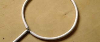
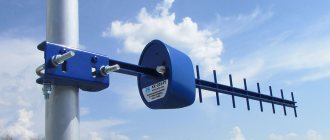
- Try to build a combined antenna containing an element in the form of a circle made of wire 55.5 cm long (see photo below);
- With its help it will be possible to receive all known formats (including 3g mobile communications).
It will be interesting➡ Ways to check transistors for functionality
In the case when you need to make a structure for receiving Internet signals, including Bluetooth, WiFi (3g, 4g) or mobile communication channels operating on ultra-short waves, the dimensions of such an antenna will be very miniature.
Kharchenko antenna made of two circles.
Due to the high frequency, the dimensions of the antenna for 3g will be limited to a length of 10 centimeters, and all possible varieties of a homemade product can be assembled using the same drawing. Significant differences regarding all possible versions of a miniature antenna (for Bluetooth or for a cell phone) will appear only in the dimensions of the receiving structure itself. The calculation procedure in this case is determined by the method of using a specific network resource (these methods are widely represented on the network for both T2 and other TV signal formats).
Improving WiFi and Bluetooth quality
It is known that the WiFi signal is transmitted, like other types of terrestrial communications, over a radio channel, which allows the use of an antenna design to improve the reception of a router or similar devices. According to a number of craftsmen from among the developers of 3g antennas, if in the design discussed above a parabolic dish is taken as a screen, the gain at WiFi frequencies can be increased to 31 dB.
Such a screen can be made from a tin can bent in a certain way. When making a reflector for 3g or WiFi, the curvature of its surface is usually selected experimentally. To do this, a program must be installed on the transmitting/receiving device (router, for example) that can record the level of the signal entering the device. Using such a program, it will be possible, by changing the curvature of the surface of a homemade screen, to monitor all changes in the gain (in real time).
Kharchenko antenna for different types of signals.
What about the amplifier
For maximum long-range reception, you can connect an amplifier to the antenna. The latter comes in two types:
- external (remote), which is attached after the antenna, cuts into the cable indoors;
- internal, connected directly to the antenna, hidden, as a rule, in a plastic case.
There are no internal issues; you just need to cut the cable in the right place and make the connection through two F-connectors.
But the outer one is attached to two bends on the diamond at once. Therefore, it is additionally necessary to consider the protection (box).
In addition to installing the amplifier, it is necessary to provide power to the antenna.
If the Kharchenko antenna is connected directly to the TV, then an external power supply is required.
Then the cable from the antenna is inserted into the TV through a separator, which is located on the power supply wire.
It is necessary to “crawl” the amplifier as close to the antenna as possible. Ideally, immediately after installing the cable into the apartment.
If a digital set-top box is connected to the TV, then you can supply power through the device search menu. In this case, an external power supply is not needed.
Connection
One end of the cable with a resistance of 50-75 Ohms is soldered to the finished antenna, the other to the plug. It is better to connect the cable to the upper part of the base, and use the lower part as fasteners.
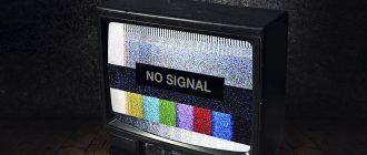
The quality of image and sound during digital television broadcasting will not depend on the distance at which the transmission will take place, unlike analogue broadcasting. If the antenna is manufactured correctly, signal transmission to the receiver will occur in normal quality and no difficulties should arise.
However, if a failure occurs, the signal will completely disappear (the sound and picture will disappear). Unlike analog television, the digital picture quality on all channels is the same and there can be no differences.
Double square for 3G and 4G
The manufacturing algorithm is identical to the antenna for receiving T2 channels. The only difference is in the calculations; the design will have different dimensions.
You need to find out the frequencies on which the 3G and 4G signal is broadcast. Each mobile operator transmits a signal on an individual frequency. But for all providers the valid range is 1.9-2.1 GHz. Applying these numbers to the formula, we get an estimated wavelength of 14-16 cm.
Based on this, the size of one side will be:
- 35 mm for 1.9 GHz;
- 40 mm for 2.1 GHz.
The reflector is mounted at a distance of 23 mm from the main frame. Instead of an antenna plug, a familiar 3.5 mm plug is mounted on the second end of the wire. It connects to the antenna socket of the Internet modem.
If the modem does not have a connector for an external antenna, then you need to disassemble the device and connect a homemade device.
Tests
And finally, a performance check and a rough
assessment of the quality of the resulting antenna.
In fact, everything is simple with the test - turn it on, it works! And to evaluate whether the game was “worth the candle,” let’s compare the parameters of the received signal from the manufactured antenna with the one I’m already using at the dacha, with a declared gain of 11dBi
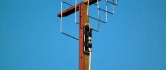
The antenna is installed in the attic of a country house, at a distance of approximately 16 km from the tower.
Signal level: factory stationary antenna on the left / homemade on the right
At first glance, the difference is only 1% (95 versus 94) - but this is not a completely correct comparison, since my external antenna is connected through a splitter, which further weakens the signal.
Mobile phone antenna
Phones operating on the GSM communication standard receive high-frequency ultrashort wave signals (900 or 1800 MHz). The higher the frequency, the further the transmission, but the less ability to bypass obstacles. This means that in built-up areas a signal with a frequency of 900 MHz works more efficiently. And in distant, spacious areas, for example, in the countryside, in a country house, a frequency of 900 MHz would be better.
Such an antenna for strengthening mobile communications is more relevant in the suburban area. Therefore, it is necessary to build a structure that will be calculated at a frequency of 900 MHz.
We obtain the wavelength using the basic formula: λ = 300/900 = 333 mm.
This means that the total length of the conductor is 333*2 = 666 mm. And the side size will be approximately 333/4 = 83 mm.
Modern mobile phones exclude the possibility of freely connecting an external antenna. It is possible to organize a connection only after disassembling the device. Therefore, the easiest way is to use the antenna in conjunction with an old phone that has a connector for an external receiver.
What is included in the initial data for antenna calculations?
In order for the image on the TV screen to be of high quality when using digital TV, it is important to correctly calculate the desired electromagnetic wavelength. Only with the help of accurate data can you count on an ideal result. You can find the length using a special formula:
λ = 300/F , where
F is the frequency of the received signal in MHz. Setting up an antenna is a labor-intensive process that requires time and patience. You can determine this parameter by checking the broadcast frequency in your locality. This can be done directly in the search engine or submit a request to the appropriate television and radio station. We divide the resulting result in half and get the value we need. Let's give an example: suppose a TV tower transmits a signal to the Moscow region with a frequency of 714 MHz. We substitute this value into our formula:
λ = 300 / 714 = 0.42 / 2 = 0.21 m = 21 cm
This is the length of the electromagnetic wave that the antenna will receive.
ATTENTION! In your case, the parameters will be completely different; the above calculations are performed as an example for guidance.