Television today and twenty years ago are two very different things. The number of channels, transmission range, and broadcast format have changed. But, in essence, the principle of transmitting a television signal remains the same. Radio waves of a certain frequency travel through the air; they can be received using an antenna and sent to the TV tuner. We will not consider cable and fiber optic TV signal transmission systems, as well as IPTV (broadcasting via the Internet and SMART TVs).
Just like a couple of decades ago, and today, thrifty owners have a reasonable question: how to make an antenna for a TV with your own hands? And if during the USSR there really was a problem in purchasing a high-quality TV antenna (total shortage), today a TV antenna is made with your own hands solely for reasons of economy.
Options for homemade designs: general principles
Depending on the distance between your TV receiver and the transmitting antenna of the television center, the signal level will change. Another negative factor affecting the quality of television wave propagation is the presence of obstacles. Ideal reception occurs when there is a direct line of sight between the two antennas. That is, you can see the mast of the television center, even through binoculars. If there are buildings or tall trees in the path of the TV signal, there will be no reliable reception. However, waves reflected from other objects can be received by a TV antenna amplifier. If even weak waves do not “break through” to your house, you will have to make a mast. The network of television and radio broadcasting stations is located in such a way that you can receive a signal in any locality.
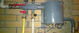
- Indoor antenna. Operates without an amplifier in relative proximity to the transmitting mast. If you can see the television center from your window, some of the channels can be caught literally with a piece of wire. How to make a television antenna with your own hands can be seen in the illustration.
The quality of workmanship in such conditions affects only the aesthetic component. But if you live on the 1st–3rd floor, and even surrounded by concrete boxes of a residential neighborhood, a simple design will not work. An indoor antenna, especially one made by yourself, will require a signal amplifier.Information: Indoor version, these are not necessarily the classic “horns” installed on top of the TV receiver. The product can be located on the wall, in a window opening, inside a glazed loggia.
The advantage of this design is that there is no need for weather protection.
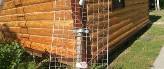
- Street TV the antenna may look exactly the same as an indoor one. In this case, a prerequisite is high strength (so that the wind does not change the geometry) and protection of the contact group from corrosion. It is usually placed in close proximity to the window (in high-rise buildings) or on the roof of a private household. The connecting cable is relatively short, so an amplifier is not required to reliably receive a digital or analog signal. Except when the transmitting center is far away.
The structure is accessible for maintenance and repair; this is an undeniable advantage of being located nearby. - Outdoor antenna for long-range TV. As a rule, this is a rather bulky design with a screen and additional elements that amplify a weak signal. An electronic amplifier is welcome, but with proper design it may not be needed. Perhaps to compensate for a long cable (there will definitely be losses in it). Such devices are mounted on the roofs of high-rise buildings or on masts in private households. The fastening must be strong, otherwise the wind can easily destroy the structure.
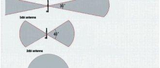
- The antenna type is selected based on the reception characteristics and wind load in the region. For example, the Kharchenko antenna (the most popular homemade option) should not have a high windage. It may be necessary to choose another, more complex project.
Next, let's look at examples of making antennas at home using scrap materials, from simple to complex.
Beer cans (Pepsi-Cola cans work too)
Why is this material so popular?
- firstly, the missing segment sizes are compensated by a large receiving area: if you unfold the can into a plane, you get a standard sheet;
- secondly, aluminum has excellent conductivity, falling slightly short of copper: accordingly, resistance losses will be minimal;
- thirdly, the aerodynamic shape reduces windage (which is especially important when placed outdoors), and the lightness of the structure does not require particularly strong fastening;
- and, finally, this is an affordable and absolutely free raw material; in addition, lacquered aluminum perfectly resists the influence of moisture.
Important!
Before making an antenna out of beer cans, make sure that there are no high-rise buildings between the television center and the reception point that could block the signal.
Despite the relatively high reception quality, this design does not have a high self-gain factor. Connecting a standard amplifier may not have an effect due to the complexity of selecting coefficients.
Necessary materials:
- Two identical liter beer cans, washed and dried. As a last resort, you can use half-liter ones, but the reception range will be reduced.
- Antenna cable RK-75 of the required length (a design with a wiring length of more than 10 meters will most likely not provide reliable reception).
- Antenna plug to match your TV.
- A dielectric fastening bracket for fastening cans: a wooden block, clothes hangers, a plastic pipe (metal-plastic will not work).
- Fastening elements: electrical tape, tape, or plastic clamps.
- Soldering iron, standard solder, flux for soldering aluminum.
- Knife, side cutters, sandpaper.
There is no point in describing formulas for calculating sizes based on the reception frequency; anyway, it will not be possible to change the sizes of the segments. This DIY antenna made from beer cans has been tested many times under various conditions, so we’ll just use a ready-made sample.
We cut the antenna cable. There will be a plug at one end, open the other end so that there is at least 100 mm from the central core to the screen wound into a bundle. To prevent the “bare” braid from being exposed to corrosion, it can be hidden in a heat-shrinkable casing.
We clean the areas for soldering the cable: at the upper ends of the cans. Fine sandpaper is suitable for this.
Important:
Stripping is carried out immediately before soldering and to the “bare” metal.
We roll each end of the wire into a ring 3–5 mm in diameter and carefully coat it with solder. Then we screw the resulting terminal to the can using a galvanized self-tapping screw. After that, we clean the joints with flux and solder until the solder “sticks” normally.
We fix the cans (from the point of view of the theory of radio reception, these are now symmetrical vibrators) so that there is exactly 75 mm between the ends with the cable. This is the optimal gap for receiving analog and digital television.
An important step: setting up the product for optimal TV signal reception. Most likely, you know the direction to the broadcast center tower. If not, Yandex cards will help you. Find a television center, your home, and conduct a virtual live broadcast. If you don’t want to bother with azimuth (this is impossible without a compass), determine the direction reference within your visibility zone. For example, a boiler room pipe or another object. For reliable reception, the home TV antenna is positioned strictly perpendicular to the vector to the tower, and horizontally.
If the signal is received reliably, you were lucky the first time. At a considerable distance from the transmitter, you can catch the reflected signal. Even a simple antenna made from cans requires correct orientation in space (although it is not a satellite dish). In an area of uncertain reception, all-wave technology can unexpectedly “shoot” in any direction.
A do-it-yourself “beer” decimeter antenna allows you to confidently catch analogue channels. How to make an antenna for digital TV? No additional secrets. Digital broadcasting is produced in the same range. If you have a DVB-T2 tuner, you can tune in to one or two multiplexes, and receive a free set of Russian channels on beer cans.
Information:
If the signal strength is still not enough, you can make an antenna amplifier yourself.
Typical diagram in the illustration:
However, in order to solder and configure such a device yourself, basic knowledge of radio engineering is required. Still, it’s easier to buy a ready-made device, especially since you’ve already saved on the antenna.
From coaxial cable
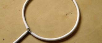
You can actually make a TV antenna manually using a cable:
- Cut approximately 530 millimeters of cable.
- Strip the cable on both sides, fastening the braid into a bundle and exposing the central core.
- Twist the cable into a ring or diamond shape and secure it with tape to the plywood. The distance between the cable rings should be 2 centimeters.
- Cut a piece of coaxial cable - 175 centimeters. Make a horseshoe-shaped matching device out of it. To do this, you need to strip the wire from both ends, as you did in the process of making rings.
- Prepare the antenna cable. The plug is put on one side, and the other is stripped. It is necessary to remove the central core and braid.
- Align the ring and matching device with the antenna cable.
As a base, you can use not only plywood, but also plexiglass.
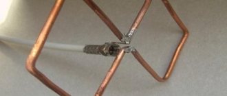
“Eight”, aka rhombus, aka “Z” shaped
Perhaps the most popular design for do-it-yourselfers. This fairly powerful Kharchenko antenna confidently receives meter and decimeter frequencies in analog and digital format. When the question arises: “How to make an antenna with your own hands?”, this option is first of all assumed.
What is its advantage? With compact dimensions, in most cases no amplifier is required. Unless you want to receive a signal on the 1st–3rd floor in a densely built-up microdistrict, where there are dozens of high-rise buildings between you and the television center.
How to make a homemade antenna without complex calculations? For a typical broadcast grid, there is a basic diamond arm size: 140 mm. Distance between wire connection points: 10–15 mm.
Kharchenko's antenna with such dimensions falls right in the middle of the typical broadcast range. If it is necessary to capture other channels (in some regions the grid may operate at non-standard frequencies), a wire structure can be made in several rows. The illustration shows a drawing from Radio magazine from 50 years ago.
Then the meter range was accepted, and the antennas had correspondingly gigantic dimensions. They were made from wire to reduce windage. This manufacturing technology requires patience and a large amount of material. Modern “homemade” people prefer a copper tube or an aluminum plate.
To make an indoor antenna using this technology, all you need is a piece of wire. The device hangs in the window opening (in the direction of the television center) and there is no need to worry about it being bent by the wind. Several diamonds can be made, and the reception range will be significantly expanded. An ideal option for digital television, which you can do yourself at the dacha or in a private home.
We amplify the signal without an amplifier
The reception efficiency (primarily this concerns the option under consideration) can be increased without additional electronics. It is enough to install a reflector or reflective screen. It will return television waves back to the antenna field, almost doubling the level. The canvas is located at a distance of 100 mm on the opposite side of the TV tower. A prerequisite is no electrical contact. Moreover, the reflector does not have to be solid. A series of metal tubes or openwork mesh is sufficient.
You can enhance the effect by using the “double biquadrate” design. The same dimensions apply, but the range remains the same. The extra length simply increases the signal strength.
Types of receiving antennas
- Linear. It is a horizontal metal rod with vertical iron dowels.
- Phased array. Made in the form of a huge air conditioner with many emitters.
- Mirror. A plate familiar to everyone, in the opening of which an electromagnetic field is formed.
- Horn. It is made in the form of a metal horn, consisting of a channel through which an electromagnetic wave passes.
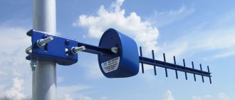
And finally, the most complex antenna for digital TV that you can make yourself
The log-periodic circuit allows you to get maximum gain without additional circuits.
The principle of operation of the design: in the direction of the signal source there are two conductive busbars, on which perpendicular vibrators are installed in strict sequence. Their length and distance between each other are calculated according to a strict algorithm. An error of 2–5% will lead to complete system inoperability. But a properly assembled antenna will receive analog and digital signals with the highest quality.
Note:
This type of antenna requires careful orientation towards the TV tower.
Can be used with a screen that helps strengthen a weak signal.
Vibrator connection
Considering the fact that the frame is symmetrical, and the connection is made to an asymmetrical antenna cable, you need to use a matching device. The best option is a short-circuited loop. It is made from pieces of coaxial cable. The left segment is a feeder, and the right one is usually called a train. In the place where the feeder and cable will be connected, we fix the cable, which is subsequently connected to the TV.
What should be the length of these segments? The calculation is carried out in accordance with the wavelength of the received TV signal.
At one end you need to cut the cable, removing the aluminum screen. The braid must be twisted into a tight rope. We cut off the central conductor down to the insulation. The feeder also needs to be cut. Remove the screen, made of aluminum, and then twist the braid. However, we leave the central conductor.
The further assembly process is carried out as follows:
- Solder the cable braid and feeder conductor to the left edge of the vibrator.
- The feeder braid needs to be soldered to the right edge of the vibrator.
- A metal jumper connects the cable braid to the lower end of the feeder. These elements can also be fastened with metal wire. The main thing is that there is proper contact with the braid.
- The braid determines not only the electrical connection, but also the distance between the sections of the matching device.
- If there is no metal wire and jumper, then twist the braided lower part of the cable into a bundle, after first removing the screen and removing the insulation. To ensure proper contact, you need to solder the wire harnesses using solder that melts easily.
- The cable pieces should be parallel to each other. Distance – 50 millimeters (small error is acceptable). To secure the distance, special clamps made of electrical insulating materials are used. You can also attach the matching device to the textolite plate.
- The cable that is inserted into the TV socket should be soldered to the feeder (to the bottom). The braids are interconnected, like the central conductors.
To reduce the number of connecting elements, the feeder and cable connected to the TV can be made one. Remove the insulation where the feeder ends. This is done in order to install the jumper.
A matching device is a mandatory element that helps prevent interference. It will be especially useful if the signal transmitter (TV tower) is located at a great distance.