Optosimistors refers to a type of optocouplers with excellent electrical parameters. They create extremely reliable galvanic isolation that can withstand a voltage of about 7.5 kV between the connected controlled load and the control circuit.
These radio components are constructed from a gallium arsenide IR LED coupled to a silicon dual-channel switch. In turn, this switch may contain an unlocking element, which is turned on at the moment the AC supply voltage crosses zero.
Optosimistors are unusually useful in monitoring more powerful triacs. Similar optosimistors were designed to implement communication between a load that is powered by 220 volts AC and low-voltage logic.
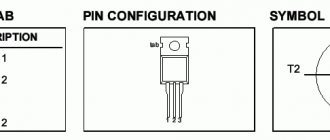
An optosimistor, as a rule, is produced in a compact DIP package with six contacts. Its internal circuit, parameters, as well as pinout are shown below.
Parameters MOC3061, MOC3062, MOC3063
Low-voltage part of the thyristor optocoupler
Maximum permissible voltage between input and output part: 7500 V AC at 50 Hz, exposure time 1 second. So this circuit eliminates breakdown even in the event of very strong voltage surges in the network.
Maximum reverse voltage on LED: 6 V.
Maximum forward voltage: 1.5 V.
Maximum forward LED current: 60 mA.
Minimum turn-on current (current through the LED at which the optothyristor turns on): MOC3061 – 15 mA, MOC3062 – 10 mA, MOC3063 – 5 mA.
High-voltage part of the thyristor optocoupler
Maximum closed voltage: 600 V.
Pulse current: 1 A with a duration of less than 100 μs.
Maximum open voltage: 3 V.
Maximum continuous current in open state: 50 mA.
Holding current (minimum current at which the thyristor does not close): µA.
Turn-on time: 1 µs. Turn-off time 10 µs. The data is approximate and is not given in the reference book; we obtained it as a result of measurements on one specimen.
Voltage at which the photothyristor can open: 5 – 20 V. This parameter has a large technological spread and strongly depends on the current through the LED. If the voltage exceeds the specified value at the corresponding input current, then the thyristor does not open. This occurs due to the operation of the zero detector circuit.
The operating mode of the optocoupler should be selected so that the control current is 10% - 15% higher than the minimum turn-on current. Then the switching on will occur only at a minimum voltage value on the photothyristor. An increase in the control current leads to additional power dissipation and an increase in voltage at which the photothyristor can be turned on, which is undesirable.
Triac key
For galvanic isolation of control and power circuits, it is better to use an optocoupler or a special triac driver. For example, MOC3023M or MOC3052.
These optocouplers consist of an infrared LED and a phototriac. This phototriac can be used to control a powerful triac switch.
In the MOC3052, the voltage drop across the LED is 3 V and the current is 60 mA, so when connecting to a microcontroller, you may have to use an additional transistor switch.
The built-in triac is designed for voltage up to 600 V and current up to 1 A. This is enough to control powerful household appliances through a second power triac.
Consider a circuit for controlling a resistive load (for example, an incandescent lamp).
Thus, this optocoupler acts as a triac driver.
There are also drivers with a zero detector - for example, MOC3061. They switch only at the beginning of the period, which reduces interference in the power grid.
Resistors R1 and R2 are calculated as usual. The resistance of resistor R3 is determined based on the peak voltage in the power supply network and the unlocking current of the power triac. If you take one that is too large, the triac will not open; if it is too small, the current will flow in vain. A powerful resistor may be required.
It would be useful to recall that 230 V in the electrical network (the current standard for Russia, Ukraine and many other countries) is the value of the effective voltage. The peak voltage is .
Managing a Powerful AC Load
| Thyristor |
Connecting a potentiometer to Arduino
smart homerelay
In fact, the relay is a complete mess. Firstly, they are expensive, and secondly, to power the relay winding you need an amplifying transistor, since the weak leg of the microcontroller is not capable of such a feat. Well, thirdly, any relay is a very bulky design, especially if it is a power relay designed for high current.
If we are talking about alternating current, then it is better to use triacs or thyristors. What it is? And now I’ll tell you.
| Triac BT139 |
| Connection diagram from datasheet on MOC3041 |
If you look at it on your fingers, then a thyristor looks like a diode, even the designation is similar. It allows current to flow in one direction and does not allow it to flow in the other. But it has one feature that fundamentally distinguishes it from a diode - the control input. If the opening current is not supplied to the control input, then the thyristor will not pass current even in the forward direction. But as soon as you give even a brief impulse, it immediately opens and remains open as long as there is direct voltage. If the voltage is removed or the polarity is changed, the thyristor will close. The polarity of the control voltage should preferably match the polarity of the anode voltage.
If you connect two thyristors back-to-back in parallel, you get a triac - an excellent thing for switching AC loads.
On the positive half-wave of the sinusoid one passes, on the negative half-wave the other. Moreover, they pass only if there is a control signal. If the control signal is removed, then in the next period both thyristors will shut down and the circuit will break. Beauty and nothing more. So it should be used to control household loads.
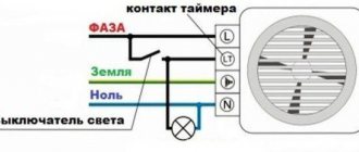
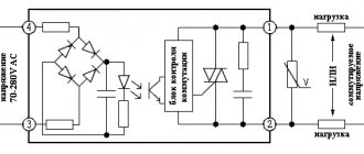
But there is one subtlety here - we are switching a high-voltage power circuit, 220 volts. And our controller is low-voltage, it operates at five volts. Therefore, in order to avoid excesses, it is necessary to make a potential decoupling. That is, make sure that there is no direct electrical connection between the high-voltage and low-voltage parts. For example, make optical separation. There is a special assembly for this - the MOC3041 triac optodriver. A wonderful thing! Look at the connection diagram - just a few additional parts and you have the power and control parts separated from each other. The main thing is that the voltage for which the capacitor is designed is one and a half to two times higher than the voltage in the outlet. You don’t have to worry about power interference when you turn the triac on and off. In the optodriver itself, the signal is supplied by an LED, which means you can safely light it from the microcontroller pin without any additional tricks.
In general, it is possible without decoupling and it will also work, but it is considered good form to always make a potential decoupling between the power and control parts. This includes the reliability and safety of the entire system. Industrial solutions are simply filled with optocouplers or all sorts of isolating amplifiers.
Well, I recommend BT139 as a triac - with a good radiator, this thing can easily carry a current of 16A through itself
How does it work and what is it for?
A triac is a semiconductor device. Its full name is symmetrical triode thyristor. Its feature is that it is possible to conduct current in both directions. This circuit element has three terminals: one is control, and the other two are power. In this article we will look at the operating principle, structure and purpose of a triac in various circuits of electrical appliances. The table below shows the characteristics of popular triacs:
Table of characteristics of popular triacs.
Design and principle of operation
The peculiarity of the triac is the bidirectional conductivity of the electric current passing through the device. The design of the device is based on the use of two back-to-back thyristors with common control. This principle of operation gave it its name from the abbreviation “symmetrical thyristors”. Since electric current can flow in both directions, it makes no sense to designate the power terminals as anode and cathode. The control electrode completes the overall picture. The triac has five transitions that allow you to organize two structures. Which one will be used depends on the location of formation (specific power terminal) of the negative polarity.
Triac.
Triac optocouplers | Techniques and Programs
One of the areas of application of optocouplers is contactless control of high-voltage circuits operating on alternating or pulsating current. For these purposes, devices are manufactured based on a photothyristor (triac - two photothyristors in one housing). Its structure and operation in circuits is similar to conventional thyristors (can be in one of two stable states). In addition to directly controlling a low-power load, such elements can be used to trigger (turn on) more powerful thyristors and triacs.
The main parameters of the most common optocouplers of this class are given in table. 8. Some of them have a built-in control circuit for detecting zero - ZCC (Zero Crossing Control), which ensures that the triac is turned on only when the supply voltage phase passes through “zero”. This implies that the switch is turned on at a voltage of about 5...20 V (due to the physical principles of operation at zero, it is impossible to turn on such elements, unlike transistors).
Table 8. Basic parameters of triac optocouplers
Note on the table
UpK - maximum permissible peak voltage between input and output; URMS - maximum permissible insulation voltage (rms value).
End table 8
Information on the interchangeability of single-channel triac optocouplers from different manufacturers is given in Table. 9.
Table 9. Options for replacing triac optocouplers
| Basic type | Complete foreign analogues (domestic version of the analogue) | Frame | Output Features |
| MOS8YU | TLP532, TCDT1110, CNY17F-2, PC714V | DIP-6 | |
| MOC811 | TLP632, IL2B | DIP-6 | |
| MOC3020 | TLP3021, K3020P, BRT12H, OPI3020, MCP3020, GE3020 | DIP-6 | |
| MOC3021 | TLP3021, GE3021, ECG3048, OPI3Q21, MCP3021, GE302t | DIP-6 | |
| MOC3022 | TLP3022, OPI3022, MCP3022, GE3022, (AOU163A)________ | DIP-6 | |
| MOC3023 | TLP3023, OPI3023, MCP3023, GE3023_ | DIP-6 | |
| MOSZOZO | TLP3041, ORTOBZO | DIP-6 | There is a ZCC scheme |
| MOSZOE1 | TLP3041, ORTOBZO | DIP-6 | There is a ZCC scheme |
| MOSZOE2 | TLP3042, ORTOBZO | DIP-6 | There is a ZCC scheme |
| MOC3040 | TLP3041, TLP3042, ORTOBZO | DIP-6 | There is a ZCC scheme |
| MOC3041 | TLP3042, ORTOBZO | DIP-6 | There is a ZCC scheme |
| MOC3042 | TLP3042, ORTOBZO | DIP-6 | There is a ZCC scheme |
| MOC3043 | TLP3043, ORTOBZO | DIP-6 | There is a ZCC scheme |
| MOSZOBO | TLP3061, ORTOBZO | DIP-6 | There is a ZCC scheme |
| M0c3061 | TLP3061, (AOU179A), ORTOBZO | DIP-6 | There is a ZCC scheme |
| MOC3062 | TLP3062, ORTOBZO | DIP-6 | There is a ZCC scheme |
| MOSZOBZ | TLP3063, ORTOBZO | DIP-6 | There is a ZCC scheme |
Note on the table
It should be taken into account that it is possible to replace optocouplers of a similar structure with better parameters, for example with a higher operating voltage: MOSZOBZ with MOC3083, etc.
When the output triac of the optocoupler is in the open state, the maximum voltage that remains at its terminals can be from 1.8 to 3 V (depending on the current in the circuit). At
Rice. 5. Pin layout and internal structure of triac optocouplers
In this case, the short-term pulse current through the load should not exceed 1 A. In order not to damage the input LED, the direct current through it should not exceed 60 mA (the voltage drop across the LED does not exceed 1.6 V, which is true for all low-power optosimistors).
Advantages and disadvantages
What is the semiconductor device in question needed for? The most popular use case is switching in AC circuits. In this regard, a triac is very convenient - using a small element you can provide control of high-voltage power. Popular solutions are when they replace a conventional electromechanical relay. The advantage of this solution is that there is no physical contact, which makes turning on the power more reliable, switching is silent, the resource is orders of magnitude longer, and the performance is higher. Another advantage of the triac is its relatively low price, which, together with the high reliability of the circuit and time between failures, looks attractive.
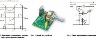
The developers were unable to completely avoid the disadvantages. Thus, devices become very hot under load. It is necessary to ensure heat dissipation. Powerful (or “power”) triacs are installed on radiators. Another drawback that affects use is the creation of harmonic interference in the electrical network by some circuits of triac regulators (for example, a household dimmer for adjusting lighting).
Note that the voltage to the load will differ from a sinusoid, which is associated with the minimum voltage and current at which switching on is possible. Because of this, only loads that do not have high power requirements should be connected. When setting the task of achieving a sinusoid, this switching method will not work. Triacs are highly susceptible to noise, transients and interference. High switching frequencies are also not supported.
Restrictions
Connecting a button to Arduino
There are limitations when using a triac, particularly with inductive loads. The limitations relate to the rate of change of voltage (dU/dt) between the main electrodes of the triac and the rate of change of operating current di/dt. Exceeding the rate of change of voltage on the triac (due to the presence of its internal capacitance), as well as the magnitude of this voltage, can lead to unwanted opening of the triac. Exceeding the rate of current rise between the main electrodes, as well as the magnitude of this current, can lead to damage to the triac. There are other parameters that are subject to restrictions in accordance with the maximum permissible operating conditions. Such parameters include the current and voltage of the control electrode, case temperature, power dissipated by the device, etc.
The danger of exceeding the rate of current rise is as follows. Thanks to the deep positive feedback, the transition of the triac to the open state occurs like an avalanche, but despite this, the unlocking process can last up to several microseconds, during which large values of current and voltage are simultaneously applied to the triac. Therefore, even though the voltage drop across a fully open triac is small, the instantaneous power during the opening of the triac can reach a large value. This is accompanied by the release of thermal energy, which does not have time to dissipate and can lead to overheating and damage to the crystal.
One way to protect a triac from voltage surges when working with an inductive load is to connect a varistor in parallel with the main terminals of the triac. To protect the triac from exceeding the rate of voltage change, a so-called snubber chain (RC circuit) is used, which is connected in a similar way.
The resistance of a triac to destruction when the permissible rate of current rise (dI/dt) is exceeded depends on the internal resistance and inductance of the power source and load. When working with a capacitive load, it is necessary to introduce appropriate inductance into the circuit.
Optosimistors in microcontroller circuits
Connection and installation of voltage relay UZM-51m
The optosimistor, as the name suggests, is turned on by illuminating the semiconductor layer. In essence, this is a combination of an optoemitter and a triac, but in one housing. The advantage is a simple control circuit and circuit isolation.
Optosimistors can switch the load themselves (Fig. 2.108, a...c) or serve as galvanic isolation for MK (Fig. 2.109, a...g).
a) direct control of the powerful optosimistor VU1 (Sharp) from MK;
b) optosimistor VU1 (optotriac from Teledyne Technologies) controls the RH load in an alternating voltage network of 220 V/16 A and has a built-in resistor Rx 440 Ohm;
c) turning on the optosimistor VU1 (replacement S201S05V) through the buffer transistor VT1, which protects the MK port in the event of an accident. Load power RH no more than 100 W.
Rice. 2.109. Schemes for galvanic isolation of triacs using optosimistors (beginning):
a) three-stage control circuit using an optosimistor VU1 and two triacs KS7, VS2. For a 220 V network, triacs (aka triacs) should be selected for a voltage of at least 600 V;
b) low-power optosimistor VU1 controls powerful triac VS1. The resistances of resistors R2, R3 vary in different circuits. Available options: VU1 - MOC3021, MOC3052; VS1 - TS112...TS142 with permissible switching voltage of at least 400 V;
c) similar to Fig. 2.109, b, but with a damping chain R4, C1, as well as with a different load location relative to the triac VS1 and a different polarity of the signal from the MK output. Possible replacements: VS1 – BT138-600, VU1 – MOC3062, MOC3063, MOC3051…MOC3053;
d) circuit diagram for connecting the triac VS1, designed for a voltage of 600 V and a current of 8 A. The capacitors must withstand an alternating voltage of at least 275 V. To increase stability, you can install a 220...470 Ohm resistor between the middle and lower terminals of the triac;
e) similar to Fig. 2.109, d, but with an active HIGH level at the MK output, a mains voltage of 120 V and with other ERI ratings. Filter L1, C2 reduces switching noise;
Rice. 2.109. Schemes for galvanic isolation of triacs using optosimistors
(ending):
e) similar to Fig. 2.109.6, but with additional noise filtering and reducing the rise of the control signal edge using capacitors C/, C2. The following options for replacing elements are: VU1 - MOC3041, VS1 - BTA12-600, R2 = 470 Ohm, R4 and C2 are absent in some circuits;
g) optosimistor VU1 controls two relatively low-voltage triacs VS1, VS2 connected in series (it is advisable to select a pair with the same leakage currents). Resistors RS, R6 distribute approximately equally the mains voltage at the midpoint of connection VS1, VS2. LEDs HL1, HL2 indicate the emergency state of the triacs or a significant asymmetry of their current-voltage characteristics. Instead of low-voltage triacs KU208B, you can install triacs KU208G with twice the permissible voltage. As a result, the reliability of the device will increase and operability will remain in the event of a breakdown of one of the triacs.
Electric motors operating on direct current
These mechanisms have a fairly wide range of uses:
- fans of computer devices;
- vehicle starters;
- powerful diesel stations;
- grain harvesters, etc.
The magnetic field of the stator of these mechanisms is created by two electromagnets, which are assembled on special cores (magnetic cores). Around them there are coils with windings.
The magnetic field of the moving element is formed by the current that passes through the brushes of the commutator unit along the winding laid in the grooves of the armature. We will definitely touch on the topic of electric motor rotor malfunction, but a little later.
MOC3041 Datasheet, MOC3041 PDF Datasheet
Manufacturer Catalog Number Components Description View
Isocom MOC3041
OPTICALLY COUPLED BILATERAL SWITCH LIGHT ACTIVATED ZERO VOLTAGE CROSSING TRIAC
Unspecified MOC3041
OPTICALLY COUPLED BILATERAL SWITCH LIGHT ACTIVATED ZERO VOLTAGE CROSSING TRIAC
Motorola => Freescale MOC3041
6-Pin DIP Zero-Cross Optoisolators Triac Driver Output
Fairchild Semiconductor MOC3041
M_
2005
6-Pin DIP Zero-Cross Optoisolators Triac Driver Output (250/400 Volt Peak)
Fairchild Semiconductor MOC3041
M 6-Pin DIP Zero-Cross Optoisolators Triac Driver Output (250/400 Volt Peak)
Isocom MOC3041
X OPTICALLY COUPLED BILATERAL SWITCH LIGHT ACTIVATED ZERO VOLTAGE CROSSING TRIAC
Unspecified MOC3041
X OPTICALLY COUPLED BILATERAL SWITCH LIGHT ACTIVATED ZERO VOLTAGE CROSSING TRIAC
Fairchild Semiconductor MOC3041
-M 6-Pin DIP Zero-Cross Optoisolators Triac Driver Output (250/400 Volt Peak)
Fairchild Semiconductor MOC3041
SM_
2005
6-Pin DIP Zero-Cross Optoisolators Triac Driver Output (250/400 Volt Peak)
Fairchild Semiconductor MOC3041
SM 6-Pin DIP Zero-Cross Optoisolators Triac Driver Output (250/400 Volt Peak)
Fairchild Semiconductor MOC3041
TM_
2005
6-Pin DIP Zero-Cross Optoisolators Triac Driver Output (250/400 Volt Peak)
Fairchild Semiconductor MOC3041
TM 6-Pin DIP Zero-Cross Optoisolators Triac Driver Output (250/400 Volt Peak)
Optosimistor: parameters and connection diagrams
Optosimistors are a type of optocouplers with excellent electrical parameters. They create extremely reliable galvanic isolation that can withstand a voltage of about 7.5 kV between the connected controlled load and the control circuit.
These radio components are constructed from a gallium arsenide IR LED coupled to a silicon dual-channel switch. In turn, this switch may contain an unlocking element, which is turned on at the moment the AC supply voltage crosses zero.
Optosimistors are unusually useful in monitoring more powerful triacs. Similar optosimistors were designed to implement communication between a load that is powered by 220 volts AC and low-voltage logic.
An optosimistor, as a rule, is produced in a compact DIP package with six contacts. Its internal circuit, parameters, as well as pinout are shown below.
Connection diagram of active load to optosimistor
There are two components in this circuit that need to be calculated, but such parameter calculations are not always actually performed. But anyway, we present these calculations of parameters for information.
Calculation of resistor parameter RD. The calculation of the resistance of this resistor depends on the smallest forward current of the IR LED, which ensures the opening of the triac. Thus,
RD = (+VDD -1.5) / If
Let’s say for a circuit with transistor control (which is used quite often in temperature controller circuits), having a 12V supply and an open transistor voltage (Uke) of 0.3 V; VDD = 11.7 V and therefore the If range is approximately 15mA for the MOC3041.
It is necessary to make If = 20 mA, taking into account the decrease in the efficiency of the LED glow during the service life (add 5 mA), we get:
RD=(11.7V - 1.5V)/0.02A = 510 Ohm.
Calculation of the resistance parameter R. The control electrode of the optosimistor can withstand a certain maximum current. Increasing this parameter disables the optocoupler. Therefore, it is necessary to calculate the resistance so that at the highest network voltage (for example, 220 V) the current does not exceed the maximum permissible parameter.
For example, let's take the maximum permissible current of 1A, then the resistance will be equal to:
R=220 V * 1.44 / 1 A = 311 Ohm.
It must be borne in mind that too much resistance of this resistor may disrupt the stability of the optosimistor.
Calculation of the resistance parameter Rg. Resistor Rg is connected only if the triac electrode has increased sensitivity. Typically, the resistance Rg is in the range from 100 ohms to 5 kohms. It is advisable to use 1 kOhm.
If the controlled load has an inductive component, then it is necessary to use a different connection circuit with protection for the power triac and optosimistor.
Connection diagram of an inductive load to an optosimistor
The signal coming from the optosimistor to the control electrode of the triac is only needed to open it. But at a high switching frequency of the switched voltage, there is a high probability of spontaneous activation of the controlled triac, even if there is no control signal.
Factors of false alarms can be voltage surges when turning on a switch connected to an inductive load, impulse noise in the load power lines. An effective way to eliminate these unpleasant moments is to use a snubber (damping) RC circuit in the circuit, which is connected parallel to the output of the key block.
The capacitor in the snubber RC circuit is metal film with a rating of 0.01 to 0.1 μF, the resistor resistance is 20...500 Ohms. These element parameters should be considered as approximate values only.
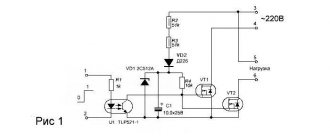
Triac switching circuit
The above circuit shows a simple triac switching circuit with a DC trigger. When switch SW1 is open, no current flows into the gate of the triac, and therefore the lamp is turned off. When SW1 is closed, gate current is supplied to the triac from battery VG through resistor R and the triac is driven into full conduction, acting as a closed switch, and the full power is consumed by the lamp from the sine wave power supply.
- Voltage stabilizer without feedback
Since the battery supplies positive gate current to the triac whenever switch SW1 is closed, the triac is constantly in the g + and ΙΙΙ + modes regardless of the polarity of the MT 2 terminal.
Of course, the problem with this simple triac switching circuit is that we would need an additional positive or negative gate power supply to drive the triac into conduction. But we can also activate the triac by using the actual AC supply voltage as the gate trigger voltage. Consider the diagram below.
The circuit shows a triac used as a simple static AC power switch providing an ON-OFF function similar in operation to the previous DC circuit. When switch SW1 is open, the triac acts as an open switch and the lamp passes zero current. When SW1 is closed, the triac is switched "ON" through current limiting resistor R and self-latching shortly after the start of each half cycle, thus transferring full power to the lamp load.
Since the power supply is sinusoidal AC, the triac is automatically switched off at the end of each AC half-cycle as an instantaneous supply voltage, and thus the load current briefly drops to zero, but is re-latched again using the opposite half-cycle of the thyristor in the next half-cycle, until the switch remains closed. This type of switching control is usually called full-wave control because both halves of the sine wave are controlled.
Since the triac is actually two SCRs connected to each other, we can continue this triac switching circuit by changing the gate firing method as shown below.
Modified triac switching circuit
As above, if switch SW1 is open in position A, then there is no gate current and the lamp is off. If the switch is in position B, then the gate current flows in each half cycle in the same way as before, and the lamp receives full power when the triac is operated in the Ι+ and ΙΙΙ– modes.
However, this time, when the switch is connected to position C, the diode will prevent the gate from firing when MT 2 is negative since the diode is reverse biased. Thus, the triac operates only in positive half-cycles, operating only in I+ mode, and the lamp lights up at half the power. Then, depending on the switch position, the load is switched off at half power or fully switched on.
Powerful power supply 0-30 V do it yourself
Features of application
Optocouplers are produced in plastic cases with six terminals. Pin 1 is marked with a dot on the body.
The manufacturer recommends connecting a 360 Ohm resistor in series with the photothyristor in power thyristor control circuits to keep the current through the high-voltage part of the optocoupler at a safe level. But this recommendation seems strange, since the optocoupler can only open if the voltage is near zero (less than 20 V or so). To ensure a safe current value, a resistor of only 20 ohms is required, provided that the opening time of the power thyristor is less than 100 μs. After all, after opening the power thyristor, the voltage on the optothyristor of the optocoupler drops to a minimum value. For common power thyristors, for example, KU201, KU202, the opening time is 10 - 20 μs.
The last remark is important, since it allows the use of these optocouplers with common power thyristors, for which 360 Ohms is too high a resistance to ensure the opening of the power thyristor at the very beginning of the half-wave with a minimum delay. For power thyristors, it makes sense to choose this resistor equal to the resistor connecting the control electrode and the cathode, which in turn is usually selected 50 - 100 Ohms.
Unfortunately, errors are periodically found in articles; they are corrected, articles are supplemented, developed, and new ones are prepared. Subscribe to the news to stay informed.
Thyristor load switching, switching (on/off). The use of thyristors as relays (switches) of alternating voltage.
Do-it-yourself uninterruptible power supply. Do it yourself UPS, UPS. Sine, sinusoid. How to make an uninterruptible power supply yourself? Pure sinusoidal output voltage, at.
Single-phase to three-phase voltage converter. Operating principle. Operating principle, assembly and commissioning of a single-phase voltage converter in three.
Thyristor switch, switch, commutator. Thyristor (SCR. Thyristor in AC switching circuits. Solid state relay circuit. .
Mobile lighting control. Sound relay. On/off. Sound relay and circuits for turning on lighting using a call on a mobile phone.
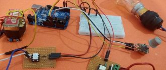
When automating a house or apartment, it is necessary to control electrical appliances operating on 220 volts. Unfortunately, the arduino controller cannot switch such a high voltage directly. A mediator is needed. The first thing that comes to mind is RELAY.
This method has both pros and cons. The advantages include galvanic isolation, the ability to switch whatever your heart desires (DC or AC, any voltage up to 250 volts)
Cons: Contacts bounce and click. Not such a big minus, but it is there.
As I have said more than once: “The main thing is family!” and if someone close to you is not comfortable, you need to try to fix it.
After my relatives said that “something clicks and scares me…” I decided to assemble a semiconductor AC switch. It was not difficult to find a detailed description and diagram of this device on the Internet.
The main characters of the AC voltage switch are a triac and an optocoupler.
The triac itself is already an AC voltage switch, but to control the triac we will use an optocoupler in order to provide galvanic isolation.
Considering various options, I decided to take the MOC3063 optocoupler. The fact is that it has a switching voltage zero transition detector. In other words, the triac will open and close at the moment when the sine wave passes through zero. This property will extend the life of switched devices...
But stop beating around the bush.
Based on my needs, I decided to make a two-channel key.
download PDF or in SprintLayout6 format download
download the program for editing printed circuit boards SprintLayout6
I made the board using the good old “laser iron” (LUT) method. Only instead of an iron a laminator was used.
Cost of parts:
- optocoupler MOC3063 — 38 rub. x2 pcs.
- triac BT138-600 — 30 rub. x2 pcs.
- resistors 6 pcs. per ruble.
- a piece of foil fiberglass - free (approximately 10-15 rubles)
- terminal blocks - can be considered free because I bought 100,500 of them a long time ago.
- We do not count ferric chloride, solder and soldering iron.
Total about 150 rubles.
Pros:
- useful for dial-up devices
- galvanic isolation
- SILENTLY!
Minuses:
- AC voltage only
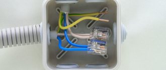
Photo of what happened:
MOC3041 Datasheet, MOC3041 PDF Datasheet
Manufacturer Catalog Number Components Description View
Isocom MOC3041
OPTICALLY COUPLED BILATERAL SWITCH LIGHT ACTIVATED ZERO VOLTAGE CROSSING TRIAC
Unspecified MOC3041
OPTICALLY COUPLED BILATERAL SWITCH LIGHT ACTIVATED ZERO VOLTAGE CROSSING TRIAC
Motorola => Freescale MOC3041
6-Pin DIP Zero-Cross Optoisolators Triac Driver Output
Fairchild Semiconductor MOC3041
M_
2005
6-Pin DIP Zero-Cross Optoisolators Triac Driver Output (250/400 Volt Peak)
Fairchild Semiconductor MOC3041
M 6-Pin DIP Zero-Cross Optoisolators Triac Driver Output (250/400 Volt Peak)
Isocom MOC3041
X OPTICALLY COUPLED BILATERAL SWITCH LIGHT ACTIVATED ZERO VOLTAGE CROSSING TRIAC
Unspecified MOC3041
X OPTICALLY COUPLED BILATERAL SWITCH LIGHT ACTIVATED ZERO VOLTAGE CROSSING TRIAC
Fairchild Semiconductor MOC3041
-M 6-Pin DIP Zero-Cross Optoisolators Triac Driver Output (250/400 Volt Peak)
Fairchild Semiconductor MOC3041
SM_
2005
6-Pin DIP Zero-Cross Optoisolators Triac Driver Output (250/400 Volt Peak)
Fairchild Semiconductor MOC3041
SM 6-Pin DIP Zero-Cross Optoisolators Triac Driver Output (250/400 Volt Peak)
Fairchild Semiconductor MOC3041
TM_
2005
6-Pin DIP Zero-Cross Optoisolators Triac Driver Output (250/400 Volt Peak)
Fairchild Semiconductor MOC3041
TM 6-Pin DIP Zero-Cross Optoisolators Triac Driver Output (250/400 Volt Peak)