Hi all! Not long ago I installed an electric Carlson instead of a forced one. I installed it on standard wires, that is, the circuit was closed stupidly through the sensor and there was no talk of any relays. Moreover, they were smart enough to parallel the button with the sensor. But after a major overhaul of the engine, there was a need to drive for some time with the propeller constantly on. Accordingly, after some time, the negligent connection made itself felt by the smoke of burning wires from behind the tidy.
Having rummaged through the Internet and books, I found, as it seemed to me, a successful connection diagram via a relay and even with a button (www.vaz2101.spb.ru/articl…ventilyatorom_p2_connect/). Everything seemed fine, but in order to assemble it all you needed not only wires and tools, but also a deep understanding of what you were doing, and since I’m not very good at auto electrics, to put it mildly.
That same deep understanding came with the study of hardware, namely the operating principle of a 4-pin relay through which all this obscenity is connected.
To be brief, the principle of its operation is identical to the operation of an electromagnetic starter, i.e. currents in the control circuit (pins 86 and 85) are closed on a coil, which closes a contact in the power circuit (30 and 87)
Thus, using the button, the coil is controlled.
The author's diagram has been slightly corrected. It took 6 meters of wire, a relay, a button in the dashboard (a fan is drawn on it).
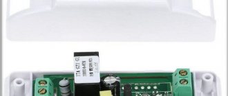
Using an electromagnetic relay
Using a simple relay will slightly complicate the circuit, but will relieve the temperature sensor from the presence of high current. A large current will flow through the relay contacts. It is cheaper and easier to replace the relay than the temperature sensor to turn on the electric fan. To carry out the upgrade, you will need a wire and a relay with a bracket for mounting to the body.
Disconnect the temperature sensor, and the wires that were on it must be connected to the normally open pair of contacts of our relay. Half the job is done, the power part is ready. Now control. We connect one terminal of the temperature sensor to ground, but connect the second to the relay coil.
From the second terminal of the coil you need to stretch the wire to the positive terminal of the battery. It is advisable that the connection be made through a fuse, the operating current of which can be 1 Ampere. The coil consumes a small amount of current, so the worst thing that can happen is a short circuit in the wiring. Subsequently, you can connect a forced activation button in parallel with the temperature sensor, which you will install in the car interior.
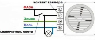
Connecting wires
Now the following connections must be made in the junction box:
- Connect the neutral wire from the supply network to the zero wire of the fan.
- Connect the phase conductor from the supply network to the conductor that goes to the incoming contact of the switch.
- Connect the phase conductor of the fan to the conductor of the wire that comes from the output contact of the switch.
In the case of a two-key switch, the distribution box will additionally have the following connections:
- The neutral conductor from the supply network will still be connected to the neutral of the lamp.
- The phase core of the lamp must be connected to the wire core that comes from the second output contact of the switch.
As you can see, nothing complicated. Be sure to consider installing a fan in the bathroom. Nowadays they come up with a lot of fashionable electrical gadgets, but half of them are complete whims. But the ventilation of a room such as a bathroom is really not an unimportant issue. So this article is relevant and useful.
Semiconductor Applications
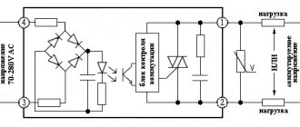
Instead of an electromagnetic relay, you can use a thyristor switch, or a design based on field-effect transistors. The essence is the same, only there are no moving contacts; their functions are performed by electrons and holes in the semiconductor crystal. But do not forget about cooling the thyristors and transistors, install radiators that will be able to provide the necessary heat transfer.
Soft engine start is a very useful function for engine control. This innovation will ensure a gradual increase in the load on the electric motor. This idea is accomplished by using PWM modulation. But along with all the innovations, you can use a second temperature sensor in the cooling system, whose response temperature is 5 degrees lower than the main one.
Fan composition
A typical fan includes:
- AC, DC motor;
- flywheel;
- buttons, relays, contactors;
- automatic regulation circuit.
Optionally there are no elements, the repair diagram looks like this:
- First of all, let's ring the motor windings. Regardless of the design, there are coils inside that give (on the tester screen) a resistance of a few to tens of ohms. Please note: the starting windings of asynchronous motors ring after the capacitor. The obvious point is that ignoring the rule leads to confusion. The capacitor rotates the voltage phase by 90 degrees, helping to create the correct field distribution inside the stator. If the motor is a commutator motor, the windings are connected in series (there is no capacitor). It is wise to ring the motor at the input, since the fault may be hidden in another place. Whether the break is detected or not, remove the brushes and take care of the commutator second. We call the sections one by one. If a malfunction is detected, the maintainability of the cooling fan is assessed by design. It's difficult to do, try to find a new manifold. Needless to say, the drum does not break in asynchronous motors with a squirrel-cage rotor. The current of the “squirrel cage” is relatively small; the copper rolled inside, on the contrary, is thick.
- Secondly, the serviceability of cores, relays, and buttons is assessed. The circuit rings, including the conditions for the thermostat to operate. The implementation method is determined by the design. Simulate heating by using a lighter to heat the sensor. The approach is reasonable in kitchen hoods and other appliances where the temperature is relatively high. The buttons are checked for the passage/interruption of electric current in their respective positions. Do-it-yourself repair of household fans often concerns switching. The buttons are pressed inaccurately and liquid spills. It is necessary to restore the correct functioning of the mechanical part and clean the contacts. Anyone who spilled jam on the TV remote control will understand the situation. The mechanism is disassembled, the contacts are cleaned. It would be useful to recall that the capacitor passes alternating current; in the best case, two operations are performed: they call the element to check for a short circuit (this is a breakdown), apply alternating current power and check the passage of the signal from the winding. We can say with complete confidence whether the capacitor is broken.
Before assembly, do not forget to lubricate the mechanical part; oil should not get between the rotor and stator. Ideally there is a uniform gap. Once you notice the difference, center the rotor (a difficult task). Sometimes bearings are missing. In domestic fans, the load is not so great that it is necessary to improve the glide. However, rubbing areas occur in any case. Rough areas are lubricated.
Button connection diagram
To be able to turn on the fan manually, the VAZ 2114 fan button is installed in the on-board network parallel to the thermal relay, which is triggered when the coolant temperature rises. There are two options for connecting the button: directly or using an electromagnetic relay.
In the first case, too much current will flow through the button contacts and will quickly fail. Therefore, correct connection of the fan must be done only through a relay. In this case, only a small current will pass through the button, controlling the relay electromagnet. A pair of wires is connected to the terminals of the relay contacts (those that are open when there is no power to the electromagnet): one from the output of the thermal relay, the other from the input. In this case, when voltage is applied to the relay electromagnet, the radiator fan will turn on. The “ground” of the relay can be connected to the nearest bolt, and the “plus” can be connected from the fuse block. Moreover, it is better to connect it to the output of the fuse, which is de-energized when the ignition is off. For example, to fuse F10. In this case, even if you forget to turn off the fan, it will stop working after turning off the ignition. Otherwise, there is a risk of draining the battery to zero by leaving the car in the parking lot with the fan on.
Connection options
If the number of contacts on the cooler connector and the fan itself matches, then there is no problem. The connectors are connected to each other, non-compliance with polarity is excluded due to the presence of a key . If they do not match, then options are possible.
3-pin to 4-pin
The three- and four-pin connectors are fully compatible with each other , both electrically and mechanically. Structurally, they are designed in such a way that the key allows the connection to be made, and there will be no pinout conflict.
Connecting a 3-pin fan to a 4-pin connector.
If the cooler has a connector with 3 pins, and a harness with 4 pins comes from the computer, then the power wires are connected at the terminal, as well as the speed measurement circuits. The PWM control wire remains unconnected.
Connecting a 4-pin fan to a 3-pin connector.
If the cooler has a connector with 4 pins, and a terminal with 3 pins comes from the computer, then on the electric motor side will remain unconnected In both cases, speed control via PWM is not possible.
Connecting directly to power supply wires
In cases where automatic airflow control is not required (usually case fans), they can be powered directly from the power supply. In this case, the coolers will turn on when the power supply starts, and stop when it turns off. It is rational to make such a connection for fans with two pins (without speed control). There are no fundamental restrictions for using 3- and 4-pin coolers in this capacity, but they are more expensive.
Molex male-female adapter with a branch to the cooler.
The easiest way is to connect a two-pin fan directly to an empty Molex connector. It is more convenient to do this using a Molex male-to-female adapter with a branch for the cooler connector. If there is no free Molex in the harness from the power supply, but there is, for example, an unused SATA power terminal, you can switch from it to Molex, and then to the fan.
The number of detachable connections should be minimized. It’s even better (if you have the skills and qualifications) to cut off the terminals, and then twist the power wires together with the following soldering and insulation of the connection point.
Installing a forced fan button for VAZ 2114
You should start work by disconnecting the ground terminal from the battery so that a short circuit does not occur during the connection of the electrical circuit. The procedure for installing the button is as follows:
- Prepare a block to which the button for forced activation of the VAZ 2114 fan will be connected. To do this, you need to leave 4 terminals with wires on it: two central ones for illuminating the button and two corner ones for controlling the power circuit of the electromagnetic relay.
- Connect two wires with lugs to the electric fan power wires that go to relay K1 (pins 30 and 87). To do this, you need to strip off some of the insulation on the wires approaching the relay and screw the pieces of wire that will go to the relay to them. Ideally, it is better to solder the connection, but you can get by with just a tight twist. The connection points must be carefully insulated.
- Connect the tips of the connected wires to the relay block to pins 30 and 87.
- Connect the control wire from the button block to terminal 85 of the relay, and connect terminal 86 with a wire to the vehicle ground. Install the fan switch button into a free slot on the dashboard, having first removed the plug.
- Install the relay in a convenient place, for example, under the dashboard of a car, and secure it.
- Connect ground to the battery.
- Turn on the ignition and press the fan button. The relay should click and the fan motor should turn on.
This completes the installation of the forced fan button on the VAZ 2114.
If the cooling fan does not work
To drive the fan, a DC electric motor with excitation from permanent magnets ME-272 or similar is installed. Technical data of the electric fan and fan switch sensor:
- Rated rotation speed of the electric motor shaft with impeller, 2500 – 2800 rpm.
- Electric motor current consumption, 14 A
- Sensor contact closure temperature, 82±2 degrees.
- Sensor contact opening temperature, 87±2 degrees.
The cooling system fan may not turn on due to:
- electric drive malfunctions;
- blown fuse;
- faulty thermostat;
- a failed thermal sensor for turning on the cooler;
- faulty VO relay;
- broken electrical wiring;
- faulty expansion tank plug.
To check the VAZ fan electric motor itself, we apply 12 V voltage from the battery to its terminals - a working motor will work. If the problem is with the fan, you can try to repair it. The problem is usually the brushes or bearings. But it happens that the electric motor fails due to a short circuit or break in the windings. In such cases, it is better to replace the entire drive.
The BO fuse is located in the mounting block of the car's engine compartment and is designated F7 (20 A). The test is carried out using a car tester turned on in probe mode.
- In a car with a carburetor engine, you need to check the sensor - turn on the ignition and short-circuit the two wires going to the sensor. The fan should turn on. If this does not happen, the problem is definitely not with the sensor.
- For injection cars, it is necessary to warm up the engine to operating temperature and disconnect the sensor connector, disconnecting it from the vehicle’s on-board network. In this case, the controller must start the fan in emergency mode. The electronic unit perceives this as a failure in the cooling system and forces the fan drive to operate in constant mode. If the drive starts, the sensor is faulty.
Installation of a hood switch
It is necessary to lay a two-wire or three-wire cable to the installation site of the switch, depending on the type of switch used. When using plasterboard walls, the wires are laid in a corrugated pipe. The ends of the cable should be located with a small margin in the distribution box and in the switch socket. The cable reserve is left for further manipulations when connecting the cores.
Before connecting the cable cores to the switch, you must remove the keys and housing. A single-key switch has two terminals: one is used to connect the phase conductor of the network, and the second is used to connect the phase output of the ventilation device.
A two-gang switch has three contact terminals. The first two have the same purpose, and the third terminal is used to connect a lighting device. A two-button switch can independently control the activation of the exhaust fan and the lighting in the bathroom.
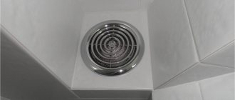
Benefits of installing a fan
The first sign of the need to install a forced ventilation device in the bathroom is the appearance of condensation, mildew or mold on surfaces in the room. Microorganisms can be a source of deterioration in the health of people living in an apartment.
Installing an exhaust device has a positive effect on the sanitary condition of the bathroom. When the hood is turned on, air masses circulate in the room: the unpleasant smell of dampness disappears, the appearance of new rust on metal surfaces stops, the growth of mold fungi stops, and damp deposits on tiles and mirrors disappear. Modern fan models do not create excessive noise, are small in size and have an aesthetic appearance.
Household fans
Household fans vary in design and use similar technical solutions. Here is a short list of places where a rotating impeller is useful:
- Refrigerator compressors certainly have forced airflow;
- Repairing the power supply fan is a common problem;
- each asynchronous motor contains a pair of impellers on the shaft for blowing the stator coils;
- no vacuum cleaner is complete without a motor with blades;
- The processor cooler is a smaller copy of a household fan;
- without a heater fan, not a single car interior will warm up properly, and repairing the fan fluid coupling has set some drivers on edge;
- kitchen, toilet and other hoods include a motor and an impeller.
An incomplete list of household appliances that use fans. The computer system unit is excessively noisy - the coolers will need to be lubricated. Carefully peel off the sticker on the fan housing with tweezers, the end of the axis comes out right here. Place a couple of drops on the sliding point and the noise should decrease. Where fans are found, the repair techniques listed above apply. Difference in size, purpose and other details.
Having studied the principles of inductance formation, begin replacing the motor stator coils. It’s a long, tedious process, it’s not recommended to do it, whoever decides to do it, take a photo of the part being repaired, bite out the wiring, wind the turns correctly, and make the reverse connection as needed. It sounds difficult, but it is more difficult to do. Often the coils have no casing. A coil of wires is inexplicably connected to neighboring coils. A household fan looks scary when disassembled. The stator has cuvettes under the wire, where it is difficult to place the turns. Nobody repairs household fan motors.
Ladies generally think that a disassembled fan is unusable, and they throw away the parts that were scattered here and there. Do not leave the opened device unattended.
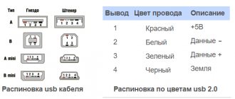
Types of cooler plugs and their pinouts
In principle, the purpose of all existing fans is to cool the hardware installed in the system unit. But there are different diagrams for connecting coolers to the power supply and depend on their design. Now there are three main types of these units, differing in the number of pins in the block, and therefore in the circuit and order of connecting the fan.
2 pin
This type of cooler, designed to cool a system unit or power supply, is perhaps the oldest. Now it is practically out of production, but you can still find it in the store. The socket of such an electrical device has two contacts.
The purpose of the wires in such a block is as follows:
- black - minus (general);
- red - +12 V.
Everything is simple here. We supply 12 volts, observing the polarity, the impeller rotates. Speed adjustment, of course, is not provided for in this design.
3 pin
This type of electric fans replaced the two-wire one. An additional wire that appears in the connector allows the computer to measure the rotation speed of the impeller and monitor the health of the cooling system using software.
3 pin connection block
The purpose of the wires in such a block will be as follows:
- black - minus (general);
- red - +12 V;
- yellow - signal from the rotation sensor.
4 pin
The most “advanced” type. Its block is equipped with another additional wire, with which the processor can change the speed of rotation of the impeller at its discretion.
Let's look at the purpose of the wires in this block:
- black - minus (general);
- yellow - +12 V;
- green - signal from the rotation sensor;
- blue—rotation speed control.
Please note that in a four-pin design, the green wire, not the yellow wire, is responsible for the signal from the rotation sensor. And yellow is now responsible for nutrition. Why such modernization was made is unknown. Possibly to confuse the average user and force him to contact a service center, and to force the especially cunning ones to burn their brand new cooler.