Ensuring good ventilation in the bathroom is a very important task. The lack of proper air exchange in this room will not ensure a comfortable stay for a person. A timer for a bathroom exhaust fan is an incredibly convenient feature. It will turn on the hood when the light in the room is turned on and turn it off after a certain time has passed after it has been turned off.
In residential and public buildings, a ventilation system is necessarily provided, which functions due to the natural flow of air, but ventilation ducts tend to become dirty over time and can no longer fully perform their main function. You can determine this in the bathroom by the following simple signs:
- the unpleasant odor lasts for a long time;
- mirror surfaces sweat;
- Condensation accumulates on walls and plumbing.
If one of these signs is present, you need to take care of installing an exhaust fan. You can purchase a timer for a fan and install it yourself, or buy a fan with a built-in timer.
How does the device work?
If the bathroom lights are turned off, the hood fan will also be turned off. In this case, the current consumption will be minimal, which will not even be recorded by electricity meters. This is the so-called standby mode.
When you turn on the lighting in the bathroom, the timer begins counting the period of time before turning on the hood, which lasts approximately 15 seconds (deviations by 1-2 seconds are possible). If you manage to turn off the light before this time is up, the fan will not turn on at all. For example, a person entered the bathroom to put or take something, which took a matter of seconds, but the hood would not turn on. This is very convenient because there is no need for the hood to operate. When the light is on for more than 15 seconds, the timer will turn on the hood fan, and it will work as long as the light is on and after it is turned off for 5 minutes. In addition, for every 2 minutes the light is on, the fan operating time after turning off is extended by another 1 minute. After turning off the light, the hood can operate for a maximum of 30 minutes. For example, if a person went into the bathroom and turned on the light, after which he stayed there for 15 minutes (took a shower or bath), then the operating time of the hood after turning off the light will be 13 minutes (5 minutes + 15 minutes/2 = 13 minutes).
The fan timer also provides the following program: after the light is turned off, the fan operating time will be the same as it worked when the light was on. Different timer fan models may have different operating intervals.
If the fan is running and the light in the bathroom is turned on again, then the duration of the fan operation will be determined as the sum of the remaining time that has not yet ended and a new period of time, which can be calculated using the described method.
The LED flashes every second to indicate that the device is operational and ready for use.
Kinds
As a rule, a timer intended for a plumbing unit means a time counter for forced ventilation systems. In fact, timers are different:
- Systems for calculating the amount of water used, which emit signals when a certain amount of liquid used is reached. This is useful when you need to fill the container with a precise amount of water, save consumption, and so on;
- Ventilation shutdown control systems, which we will talk about in more detail;
- Lighting timers;
- Timers to turn off water supply from faucets.
Photo of the purchased timer
It's no secret that when leaving home, forgetting to turn off the lights is not a problem for us at all. But electricity is far from cheap now. That's why some people use built-in timers in switches that allow them to automatically turn off the lights.
If we talk about timers on mixers, this is also a useful thing. They are used on touch-sensitive faucets, which are activated by holding your hand near a special sensor that responds to movements. Typically used in public restrooms, although some have had success at home. The time counter operates after the configured amount of time, causing the water supply to stop. Relevant for situations when we run away from home in a hurry, forgetting to turn on the valves.
Design and operating rules
The timer is a single-sided printed circuit board on which the elements are mounted. Component DD1 is connected on the conductor side, the remaining components are installed on the other side.
To protect the printed circuit board from moisture, it is recommended to open it with moisture-resistant varnish.
The most common type of timer is connected to a 220 V network and has a signal wire input from a lighting lamp. In other words, the timer is always connected to power, and the fan is already connected to it. When you turn on the light in the bathroom, a signal is sent to the timer and the time begins counting down, after which the hood turns on. When the light is turned off, the power on the signal wire disappears and the countdown begins until it turns off.
Connecting a fan in the bathroom
In residential and public buildings, small exhaust fans are often installed in bathrooms. Why they are installed, I think there is no need to explain =) Let's consider several main options for connecting such exhaust systems.
The essence of all possible ways to turn on fans in bathrooms is that their operation is associated with turning the lighting on and off.
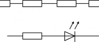
1 The fan is turned on in parallel with the lamp of the bathroom lamp.
Turning on the fan in the bathroom
This is the simplest and most inexpensive way to turn on the fan. No additional equipment is required to turn on the fan. When the lights are turned on, the fan in the bathroom also turns on.
Advantages: simple connection circuit.
Disadvantages: the fan turns off immediately after turning off the lighting.
2 Turning on the fan using the timer for bathrooms BZT-300.
Timer BZT-300 is designed to turn on and off bathroom exhaust ventilation.
The fan switching circuits together with lighting and timer are presented below:
Turning on the fan in the bathroom using the BZT-300 timer
When the switch is turned on (off) the timer first turns on the lighting, and then after 30 seconds turns on the exhaust fan. After turning off the lighting, the fan continues to run for another 5 minutes.
The power of the exhaust fan connected to the BZT-300 timer should not exceed 0.3 kW.
The timer is connected by three pairs of wires:
- A white pair of wires is connected to the fan.
- A pair of blue (gray) wires must be connected to a 220 V network.
- A pair of black wires is connected depending on the voltage of the lamps: for 220 V bathroom lighting lamps - parallel to the lamp; for 12 V lamps - parallel to the primary winding of the step-down transformer.
The timer has overall dimensions of 54x45x16mm, which allow it to be mounted in a small mounting box.
3 Turn on the fan using a time relay.
RO-406 or RO-415 (EUROAUTOMATIKA “F&F”) is suitable as a time relay. RO-406 (RO-415) – time relay with switch-off delay and control input. These relays are used to turn on bathroom fans for a specified time.
Connection diagram for fan and lighting lamp:
Time relay with switch-on delay and control input
When you turn on the lighting in the bathroom (switch S), the fan turns on simultaneously with the lighting. After turning off the lighting, the timer starts counting down, after which the fan also turns off.
Compared to the BZT-300, the RO-406 (RO-415) timers allow you to set a shutdown delay from 1 to 15 minutes and allow you to switch a larger load: 8 and 16A, respectively.
4 Turn on the fan using pass-through switches.
The most unusual way to turn on the fan in the bathroom. I only used it once. I once built a restaurant and the exhaust fan was designed for two bathrooms, the bathrooms were located next to each other, but the entrances were from different corridors. I installed two pass-through switches to turn on the fan from each corridor, but the circuit for turning on the fan is not connected with turning on the lighting.
If possible, turn on the fan in the bathroom using the second or third option. As a last resort - according to the first one.
I recommend reading:
Distance between down conductors according to TKP 336-2011
How to determine the category of electricity supply?
Is there a future for designing in AutoCADe?
Can a working light be a backup?
Fan connection diagrams
How can you implement the wiring diagram for a fan with a timer from Era or any other manufacturer? It’s worth noting right away that you don’t have to entrust such work to specialists; you can do everything yourself. At the same time, installing the device itself is not a problem, and that’s only half the battle. The main thing is to apply voltage to it. And since we are considering fans that are equipped with a timer, there are not many options:
- Connection via a switch - that is, parallel to the lighting.
- Connection directly to the distribution box - a fully automated system without human intervention.
It is worth noting that all these options are best implemented at the stage of renovation or construction of a new facility. Then the wires will be securely hidden under the tiles or plaster. Otherwise it presents certain difficulties.
DIY installation instructions
There is no need to call a specialist; you can install the device yourself.
Preparatory work
First you need to select the appropriate unit model. Then the cable is laid and brought to the structure. Its dimensions must correspond to the dimensions of the ventilation duct - the device must fit tightly into it.
Required tools and materials
You need to prepare in advance:
- drill;
- drill;
- insulating tape;
- pliers;
- screwdriver;
- screws.
The connected device requires:
- screwdriver;
- knife;
- electrical wire;
- terminals;
- switch.
It would be a good idea to install a decorative wiring box.
Connection methods
There are three ways to optimize the operation of an exhaust fan:
- The device and lighting turn on at the same time. The advantages include simplicity and affordable cost. The disadvantage is that you have to leave the light on until the moisture disappears.
- Direct connection. The electrical appliance operates when necessary.
- Device with built-in switch. Switching on/off is done via a cord.
- Exhaust fan with timer. The engine starts at a certain time.
Connection diagram and connection of wires in the distribution box
Connection diagram and connection of wires in the distribution box
Connect directly
You can directly connect the device from an existing lamp.
Connection via one-key switch
Several electrical appliances are connected in parallel or a power supply is used. Since these devices often use metal components, grounding is necessary, especially in humid conditions.
Connection via two-button switch
The connection is based on two contacts of the switch, where different phase wires go off. The options are independent of each other.
Electrical diagram for connecting a fan from a two-key switch
Fan connection diagram from a two-key switch
Fan with built-in switch
The built-in switch eliminates the need to use an external switch or other switching systems. More often it is made in the form of a cord, which is quite convenient to use.
Combined connection of fan and lighting via a single-key switch
A good connection option is to connect the ventilation structure and light using a single-key switch. Of course, you have to turn on the system even if your visit to the bathroom is short. But fan models with an electronic timer are produced. The mode switch in such designs consists of three pins, two of which are connected by a jumper, so there are 2 operating modes.
Fans with a timer are a good solution
We have already become familiar with the need for a forced ventilation system - it is enough to install an exhaust device. However, in comparison with conventional models, analogues with a clock device have much greater advantages. By implementing in practice the connection diagram for a fan with a timer, you can bring the ventilation to almost ideal.
First of all, we are talking about saving electrical energy. The fan, which is powered in parallel with the lighting, will turn on even when the owner simply goes into the bathroom to wash his hands or load dirty laundry into the washing machine. That is, the device starts working even if there is no need for air exchange.
The operation of models with a timer is due to a long stay in the bathroom and in this case it is no longer possible to do without air circulation. As a result, the fan functions, as they say, strictly to the point.
Option - manual switching on, switching off delay
Here you will need a special fan with a built-in timer. On average, it is about 500 rubles more expensive than usual. You need to place a button on the wall (monostable switch), pressing which will turn on the fan for a specified time. That is, we can turn on the hood ourselves when we need it. You need to provide this button in advance and put some clear pictogram on it, but the fan will not make noise when it is not needed.
If you take a slightly more advanced fan with a humidity sensor, it will automatically turn on when the humidity rises, that is, when someone uses the shower.
By the way, I have implemented this option at home. I personally find it the most convenient.
Features of the right choice
When using a fan connection diagram with a timer in a bathroom or toilet, the choice of the device itself is also of considerable importance. To do this, you must first pay attention to its main characteristics:
- performance;
- electrical safety;
- noise level.
The performance of the appliance is largely determined by the volume of the bathroom, including the number of people using it. To calculate this parameter, you need to remember one formula, well known from school: multiply three quantities together: length, width and height.
After this, the obtained result must be multiplied by the frequency of ventilation. According to SNiP, this figure for a family of three is 6, for a larger number of people it is 8. The number will ultimately be the fan’s performance. In this case, it is better to choose a device with a value slightly larger than the calculations obtained.
In the connection diagram for a fan with a Vents timer, for example, the degree of electrical safety is no less important than performance, if not more. And since the device must operate in a room with a high level of humidity, then this indicator should vary from IPX3 to IPX5. This indicates that the device body is reliably protected from splashes and moisture, including direct contact with a jet of water. It is not worth purchasing one of the options with a higher protection class for a bathroom in an apartment or private house due to its inexpediency. This is not an industrial premises.
Regarding the noise level, there is only one condition: the quieter the fan is, the better. That is, you should choose those models whose operating volume is no more than 30 dB. This is especially true if it is necessary to carry out ventilation at night.
Fan characteristics
The correct choice of device cannot be made without knowing its technical parameters and characteristics. The timer fan has the following features:
- power. In order to determine the required performance, you need to measure the volume of the bathroom and multiply the result by 8 (the air exchange rate recommended by sanitary standards). The resulting power is the minimum required;
- noise level. Fans are produced both with and without noise suppressors. The exact value of the noise produced can be found in the device data sheet. If it exceeds 30-35 dB, installing such a fan in the bathroom is not advisable;
- control type. The timer on the fan can be set in a variety of ways. By pressing buttons on the device, turning a mechanical relay or a signal from the control panel. You need to choose the most convenient method, although it will not have to be adjusted too often;
- humidity sensor. Using this sensor, it is possible to automatically turn on when a critical humidity level is reached and turn off when it drops to the required level, or turn on after a person enters, and turn off after a decrease in humidity or by a timer signal. This helps reduce energy consumption.
electrical safety
Compliance with safety rules in rooms with high humidity is very important. There must be a mark on the body of the device indicating the possibility of its use in such a place. It is acceptable to use a fan with a timer with a class of IPX3 or higher.
| Class | Water protection level |
| IPX0 | No protection |
| IPX1 | Only from drops falling vertically |
| IPX2 | From drops falling at an incline of <15 degrees |
| IPX3 | From spraying water |
| IPX4 | From splashes |
| IPX5 | From water jets |
There is no need to use devices with a class higher than IPX5.
Reasons for installing a fan
The main sign that indicates the need to install a fan in the ventilation duct is the appearance of condensation and, as a result, mold and mildew on various surfaces of the room. These pathogenic microorganisms can serve as a source of various types of infections that affect residents of an apartment or private country house. In addition, the premises of an apartment or house can be filled with odors from neighbors below or above. This also suggests that natural ventilation is not working well.
The use of a connection diagram for an extractor hood fan with a timer in the bathroom helps improve the sanitary environment of the room. When the device is turned on, the air mass circulates, which leads to the disappearance of unpleasant odors. On metal surfaces (again due to the high level of humidity), the appearance of new rust is stopped.
As for the proliferation of fungi, their growth also stops. In addition, damp deposits on tiles (and such material is present in the design of many bathrooms) and mirrors disappear.
There are different models of fans on sale, among which you can find modern devices that operate silently. In addition, they have a rather attractive design and compact size.
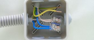
Wiring diagram in the bathroom for a fan with a timer
As you can see, you need to run a three-wire cable to the exhaust fan.
Now, knowing the connection diagram, you can proceed directly to installation.
Option - delayed shutdown
This is an evolution of option 2, and quite significant. Let's look at the control units for the exhaust fan from Noolight (Belarus).
The BZT-300-SU unit is connected to a 230V power supply, an exhaust fan (to control it) and a bathroom lighting (to understand when it turns on). The timer turns on the fan 30 seconds after the lights are turned on and turns off the fan 5 minutes after the lights turn off. Not bad already. If we logged in for less than 30 seconds, then we won’t hear it. And 5 minutes of work will be enough for ventilation.
The BZT-300-SUF block is even cooler. There is no need to connect a lamp to it; it has a built-in photocell that will understand when the light turns on. And the turn-on delay and turn-off delay times are adjusted with knobs on the block, as is the sensitivity of the light sensor. The block costs about 500 rubles, but greatly adds comfort.
Hood timer
During the last apartment renovation, I thought about improving the living standards.
One of the amenities implemented was a timer for the hood in the bathroom. On the one hand, this increased comfort, since the device itself turned off the fan, on the other hand, it had a positive effect on saving electricity. The following describes the description and implementation of the timer. It can be easily adapted for short-term switching on of any power load up to 1 kW. A household exhaust fan operates on 230 Volt AC power and contains a motor with a power of 15 ... 60 W. Therefore, when developing the timer, it was decided to use a BT134 triac as a switching element. It can handle DC current up to 4 Amps and can operate without a heatsink for this load. The control part is made on a cheap 8-pin microcontroller. This allows you to modify the program to suit your specific needs. For example, add a humidity sensor or change the operating mode and counted time interval.
In this version, two operating modes are implemented. After pressing the button, the timer turns on the fan and goes into mode 1, signaling with a green LED light. After the set time (5 minutes) the hood turns off. If you press the button again during mode 1, the timer will switch to mode 2, turning on the red LED. In this mode, the fan runs continuously until the button is pressed again.
Electrical circuit diagram:
The power supply is made on the LNK302 chip manufactured by Power Integrations. Thanks to this, the resulting IP is small in size, with high efficiency and a small number of parts. The microcircuit implements all the basic protections: against short circuit, against feedback loss, against input emissions, and overheating. I will not dwell on it in detail, since all the necessary information, if desired, can be found in the datasheet. Resistors R4 and R3 form a divider that determines the level of voltage stabilization at the output. Resistors R1 and R2 are used as a fuse, so it is advisable to use output MLT-0.25.
ATTENTION! The power source has a galvanic connection with a 230 Volt network, so all installation and adjustment work must be carried out with the device turned off and in compliance with safety precautions!
The timer and control part are made on a PIC12F629 microcontroller. A two-color LED, a button and an optosimistor that controls the VS1 key are connected to it. A fuse is installed in the load circuit, not indicated in the diagram. Its value is selected based on the fan parameters.
The implementation of the design depends on specific conditions. For example, I had a free switch box, so it was decided to mount the timer in it. A TV socket purchased from an electrical goods store was adapted for the exterior design. The antenna connector was removed from it, the housing was drilled to mount a two-color LED, and a button was selected. Then the printed circuit board was laid out and manufactured. Therefore, be careful, the supplied printed circuit board may need to be adjusted to suit your case.
The printed circuit board is made of single-sided fiberglass measuring 45 x 45 mm. Some elements on it are duplicated with SMD cases so that you can install what is available. I installed an SMD choke, but if there is only an output choke, you can drill holes for it in the pads.
Printed circuit board drawing (view from the solder side):
Installation of output elements:
Installation of SMD elements:
Program source code:
title “TimerVent”; Timer program for hood control errorlevel 0, -207, -302 #include CBLOCK 0x020 ;Definition of tmp variables; temporary registers del, del_m; to generate delay cfg ; configuration register time_h, time_l ; to count the operating period ENDC __CONFIG _CPD_OFF & _CP_OFF & _BODEN_ON & _MCLRE_OFF & _PWRTE_ON & _WDT_OFF & _INTRC_OSC_NOCLKOUT #define SET_LED_K bsf GPIO, 5 ; Light up the red LED #define SET_LED_Z bsf GPIO, 4 ; Light up the green LED #define ZERO_LED_K bcf GPIO, 5 ; Turn off the red LED #define ZERO_LED_Z bcf GPIO, 4 ; Turn off the green LED #define SET_MOTOR bsf GPIO, 2 ; Turn on the load (motor) KNOPKA equ 1 ; The button is connected to port 1 org 0 goto INIT ;Start the program DEL_MK movwf del ;Delay subroutine (in microseconds, 770 µs max) M1 decfsz del, F ;(Before calling, place the delay value in W) goto M1 return DEL_M movwf del_m ;Delay subroutine (in milliseconds, 256 ms max) movlw 0xa5 ;(Before calling, place the delay value in W) M2 call DEL_MK call DEL_MK decfsz del_m, F goto M2 return INIT bcf STATUS, RP0 ;Bank 0 selected movlw B'00000111′ movwf CMCON ;Disable built-in comparators clrf GPIO bsf STATUS, RP0 ;Bank 1 selected movlw B'00000010′ movwf WPU movlw B'00000000′ movwf OPTION_REG call 3FFh ;Load generator calibration constant movwf OSCCAL movlw B'00000010′ movwf T RISIO; movlw B'00000010′ ; movwf IOCB bcf STATUS, RP0 ;Bank 0 selected clrf cfg ;———————-[ SELECT NEXT MODE ]————————— SM btfsc GPIO, KNOPKA goto SM bcf T1CON, TMR1ON ;Turn off timer 1 movf cfg, F btfsc STATUS, Z goto MOD1 btfsc cfg, 0 goto MOD2 OUTP clrf GPIO ;Preparing for “shutdown” clrf cfg movlw 0xfa ;Delay for 0.5 seconds call DEL_M movlw 0xfa call DEL_M goto SM ;————— ——-[ SHORT ON MODE ]————————- MOD1 clrf cfg bsf cfg, 0 ZERO_LED_K SET_LED_Z SET_MOTOR movlw 0xfa ;Delay 0.5 seconds call DEL_M movlw 0xfa call DEL_M movlw b'00110100′ ;Configuring the timer 1 movwf T1CON clrf TMR1H clrf TMR1L clrf time_l clrf time_h bsf T1CON, TMR1ON ;Enable timer 1 M3 btfss GPIO, KNOPKA goto SM btfss PIR1, TMR1IF ;Overflow check goto M3 bcf PIR1, TMR1IF ;There was an overflow, checking the account incf time_ l, F btfsc STATUS, Z incf time_h, F movlw 0x58 ;Low byte of the time counter xorwf time_l, W btfss STATUS, Z goto M3 movlw 0x01 ;High byte of the time counter xorwf time_h, W btfss STATUS, Z goto M3 goto OUTP ;—————— —-[ MODE CONSTANTLY ON ]————————— MOD2 clrf cfg bsf cfg, 1 SET_LED_K ZERO_LED_Z SET_MOTOR movlw 0xfa ;Delay 0.5 seconds call DEL_M movlw 0xfa call DEL_M M4 btfsc GPIO, KNOPKA goto M4 goto OUTP END ;————————————————————————— ; Delay table for subroutine DEL_MK: ; 0x20 - 100 µs; 0xa5 — 500 µs ;—————————————————————————— ; Bit description cfg: ; “0” - if set, the “short on” mode is active (green); “1” - if set, the “always on” mode is active (red); "2" - ; "3" - ; "4" - ; "5" - ; “6” — ;—————————————————————————
Installation stage
With the diagram for connecting a fan with a timer to the electrical line, everything is now more or less clear; now it’s time to get down to the installation procedure. However, an electrical cable must first be laid to this place. To do this, a groove is made from the distribution box.
Now it is clear why such work is planned to be done during scheduled repairs or during the construction stage. After this, you should connect the wires to the contacts on the fan (this has already been written in more detail above).
Before installing the fan, the decorative grille is removed from the shaft channel (if it has been cleaned, it is already open). If you chose the installation method using self-tapping screws, you should drill holes for the dowels, where they will then be screwed in during the installation of the fan. At this point, the dowels themselves should already be pre-inserted into the holes made.
If necessary (if it is not possible to fasten it with self-tapping screws), you can go the other way - attach the body of the exhaust device to a special glue or sealant. At the final stage, the removed decorative panel is returned to its place.
Connect directly to the junction box
Fans with a humidity or motion sensor allow you to make air exchange in the bathroom fully automated (they are in any case equipped with a timer). That is, the participation of the home owner is not necessary at all. Even in a simple connection diagram, a fan with a timer and a humidity sensor should not include the cheapest one. In addition, you should pay attention to another point if the bathroom is separate:
- Devices with a humidity level sensor - for the bathroom.
- Fans equipped with a motion sensor – for the toilet.
The first ones will be activated automatically, as soon as the humidity level exceeds the established limits. Moreover, the hood will work until it reaches the normal parameters.
As for models with motion sensors, they are turned on when a person appears in the range of the sensors. The fans will automatically turn off after the delay set on the timer.
And since the system is fully automated and operates without human intervention, switches are not included in its connection diagram as unnecessary. For this purpose, the wires from the distribution box (phase, neutral, ground) go directly to the fan contacts.
Electrical connection
Diagram for connecting the fan to the electrical network.
Typically, the fan is connected to a lighting fixture. In this case, it starts working simultaneously with the person entering the bathroom, and ends some time set by the timer after the lights are turned off.
The cables are connected as follows:
- phase - contact L;
- zero - contact N;
- ground - ground contact;
- phase - switch - luminaire input - luminaire output - timer contact (LT).
You can also use an additional switch without connecting the device to the bathroom lighting. In this case, from the proposed circuit it is enough to remove the lamp input - lamp output fragment. This method is less convenient, since a person has to take more actions to start the device, but it allows you to save energy by not turning on the device in some cases (for example, when using a washing machine). It is most convenient if both switches are located in the same place.
If the installation is carried out at the time of renovation, the cables can be routed under the finishing materials on the walls and ceiling. If the repair has already been completed, you can use cable channels. It is necessary to ensure that large amounts of water splashes do not reach the places where they are installed. In order not to spoil the design of the bathroom, the cable channel can be laid close to the ceiling. If the ceiling is made of plastic panels, you can carefully remove them, hide the wiring under them and put them back together.
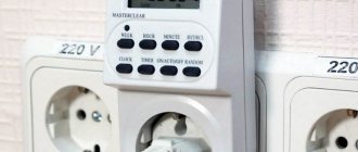
Connecting a bathroom timer
As an example of connection, we use the popular Granit-BZT-300-SU timer from the Nootekhnika company. It will work in tandem with an S&P Silent 100 exhaust fan.
The device itself is quite compact, you can see it in the image below. The maximum power of the fan connected to it should not exceed 300W.
As you can see, the timer has six contacts for connection, all of which are used during installation. And although it looks quite scary, there is nothing complicated here, especially if you understand the connection diagram.
Natural ventilation analysis
However, before you start creating a forced ventilation system, it is worth analyzing the natural one. First you need to find the shaft hole and remove the decorative panel. Over the many years of operation of the building, usually no one looks here due to lack of need (according to the residents). Therefore, you can find not only deposits of garbage and dust there, but even cobwebs.
In accordance with SNiP, air exchange parameters in a standard bathroom should be 25 m3 per hour. Therefore, when designing it, it is difficult to do without a connection diagram for an exhaust fan with a timer. Of course, in the absence of special equipment, it is impossible to determine compliance with this standard. At the same time, you can use one folk method.
After the channel is put in order, it is worth bringing a lit match, candle or lighter to it. If the flame deviates towards the shaft, then the ventilation is functioning properly. And in this case, the decision to install a fan can be made for preventive purposes, or this measure can be abandoned for now.
If this technique is not enough for someone, you can use another one - using a sheet of paper. To do this, take a small piece and lean it against the ventilation shaft:
- the leaf is holding - everything is fine;
- a piece of paper fell to the floor - conclusions in favor of installing a fan.
The connection diagram for a fan with a timer in the bathroom will be implemented at its best if there is a flow of fresh air in the room. As a rule, its circulation is achieved through a small gap under the door. It is for this reason that a threshold is not installed in this room.
Bathroom ventilation
In this room, ventilation is necessary to remove large amounts of moisture that constantly accumulates here. Thanks to the presence of a hood, it is easy to breathe in the room, plumbing fixtures and household items do not deteriorate, and mold and mildew do not appear.
Recommendations from engineers when choosing bathroom ventilation
Engineers recommend not purchasing expensive, large equipment. The main thing is to correctly calculate the required power. Experts advise paying attention to the power of the wiring in the room. Since the hood has considerable power and pressure, the cable may be damaged due to an overload of the electrical network. When purchasing, quality, productivity, and dimensions are taken into account.
How to install a fan in the bathroom
When installing, you must follow the rules:
- remove the cover;
- Lubricate the places that will be adjacent to the wall surface with liquid nails or reliable glue;
- place the product in the hole in the wall (the working part is hidden);
- press the body well;
- install a mosquito net;
- Place the cover, securing it with dowels or self-tapping screws.
At the end of the work, the wires are laid, and the structure is connected to the electrical network.
The principle of connecting to the electrical network
The ventilation duct is separately wired for automatic activation by programming the device or a motion sensor. If the model has a cord, then you can turn on the system mechanically.
Important! Wiring should be installed using terminal blocks, and not using conventional twists.
Control by turning the lighting on/off
Often electrical equipment is turned on at the moment when the lights in the room come on. But since an exhaust hood is usually necessary during bathing, this option is not very convenient - electricity is wasted, for example, during washing. Therefore, it is better to automate the system in order to save energy and provide additional convenience.
Why do you need a timer for a bathroom fan?
Equipped with a timer, the hood will turn on when the light is turned on, and turn off a few minutes after the person who took the shower has left the bathroom. During this time, the device extracts moist air. If the stay in the room was short, the structure will not turn on, since there is no need for its operation.
Connecting a bathroom timer
The timer is a compact device. It should be connected using 6 pins. To connect correctly, you need to use the diagram.
Wiring diagram in the bathroom for a fan with a timer
Wiring diagram in the bathroom for a fan with a timer
Bathroom timer connection diagram
Wiring diagram in the bathroom for a fan with a timer
Connection via switch
Before you start connecting the power wires, you need to turn off the switches on the switchboard. Then the front panel of the device is removed and wires are inserted into it through the channels.
How to connect an exhaust fan to a switch
The wires are connected to the terminals of the device located under the cover. In the absence of grounding, 2 wires are enough: phase and zero. The wires are connected to the terminals, secured with bolts, and a protective cover is installed.
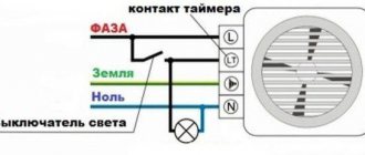
Connection diagram for a fan with a timer from a light bulb
Exhaust fans with a timer are more expensive than conventional analogues without additional equipment. However, this is a good option for use in a bathroom. In this case, the connection diagram implies the presence of a switch and looks like this. Here you will need 4 wires:
- The phase wire goes to contact L directly from the junction box.
- Contact Lt - also for supplying the phase, only through the light switch.
- Terminal N - corresponds to zero; a wire also goes directly to it from the junction box.
- The PEN contact is a ground connection for connecting the corresponding conductor.
In other words, only the phase is opened, as is the case with lighting.
With this scheme for connecting a fan with a timer, the operating algorithm is as follows. Turning on occurs simultaneously with the lighting, and turning off occurs after a certain time after turning off the light (configurable on the device). That is, the fan will work even if the owner has already left the room. Usually this is a period from 5 to 30 minutes, which is quite enough for flow ventilation.
But there are other models on sale that are equipped with a reverse mode. In other words, the fan motor will only work when the light is turned off, that is, the opposite of the first option. And then after the time set by the timer has expired.
Dergalev I.D. Timer for ventilation in the toilet room
To speed up the removal of odors, electric fans are usually used, installed in the ventilation duct. Most often, the circuit is simple and consists of a fan and a mechanical power switch. To ventilate the room you need to turn on the fan and then turn it off. This is not always convenient. It is advisable that the fan turns off on its own after some time, for example, 10-12 minutes will be quite enough for a standard toilet room. At the same time, it is desirable that in addition to the timed shutdown mode, there is also a regular manual control mode, when the fan is turned on and off using a regular switch.
Descriptions of timers for this purpose were published on the Internet, as well as on the pages of amateur radio magazines, but some were made based on a microcontroller, others based on binary counters like CD4060 or K561IE16. Of course, this is the correct and modern approach, but the microcontroller needs to be programmed, and it is not always possible to purchase the required counter. Despite the fact that this problem can be solved using a very simple circuit, built on the basis of an accessible IC with a low degree of integration.
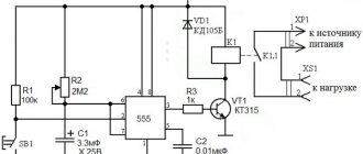
Timer circuit
In this case, this is the K561TL1 microcircuit (or an imported analogue 4093), which is a set of four 2I-NOT elements with a Schmitt trigger effect. However, this circuit will also work if you use an IC without a trigger effect, such as the K561LA7 (4011). The time is set by the RC circuit R1-C1. It can be adjusted in any direction by selecting resistance R1 (and selecting capacitance C1 is also possible). To start the time relay, use the S1 button; this is a non-latching button. When you press it, it closes the plates of capacitor C1 with each other and thus discharges it. In this case, the voltage at the inputs of D1.1 drops to zero, and the output of D1.3 will be a logical one. The voltage from output D1.3 through resistor R3 goes to the base of transistor VT1 and opens it. Relay K1 turns on the fan.
After releasing the S1 button, the charge of C1 through R1 begins, and depending on the values of C1 and R1, the voltage on C1 after some time reaches the switching threshold of element D1.1. In this case, a logical zero is set at output D1.3, transistor VT1 closes and relay K1 turns off the fan.
This is how the timer works. If you need to control the fan manually, use switch S2. When it is turned off, pin 9 of D1.3 receives a logical one voltage through resistor R2, and element D1.3 works as an inverter. When S2 is turned on, pin 9 receives a zero through S2 and its output is a logical one, the relay turns on the fan.
The power source is an inexpensive AC adapter for charging or powering USB devices from the mains. Its output voltage is 5V.
Relay K1 - BS-115C with a 5V winding. The relay can also be used with a winding for a different voltage, for example, 12V, but then the supply voltage must be raised to 12V. In general, the supply voltage can be from 5 to 15V, but the same as the voltage of the relay winding.
Timer printed circuit board with parts layout
The installation is made on the printed circuit board shown in Figure 2.
The board can be installed in one case with buttons, or the buttons can be placed in a separate case, connecting it to the board with a three-wire cable (common minus and connection points for buttons). S1 is a non-latching button, green. S2 is a button of a similar type, but with a pressed position lock, red in color.
The use of a relay and a power source with a transformer (pulse or power) provides galvanic isolation of the buttons from the mains, which is good in terms of safety in rooms with high humidity.
Dergalev I.D.
Magazine "Radioconstructor" No. 12 p. 31-2015. For home and everyday life Timer
Option - even simpler
What could be even simpler than a hood switch? Turning on the hood along with the bathroom light. It makes sense in a frequently visited public toilet, where the fan does not disturb anyone with its operation. In an apartment, this means that, firstly, the fan will turn on and make noise every time, secondly, in most cases it will turn on when it is not needed, thirdly, turning off along with the light, it will not perform its function, that is, it will not have time to draw out the air so that it can be renewed from other rooms.
Sources
- https://mr-build.ru/ventilyatciya/tajmer-ventilyatora-sanuzla.html
- https://FB.ru/article/463323/shema-podklyucheniya-ventilyatora-s-taymerom-printsip-rabotyi-i-poryadok-soedineniya
- https://home-matic.ru/2017/06/umnoe-upravlenie-vytyazhkami-sanuzlov/
- https://rozetka-online.ru/podkljuchenie-i-ustanovka/item/144-podklyuchenie-tajmera-vytyazhnogo-ventilyatora-v-sanuzle
[collapse]