A short circuit (and overload, as a special case) is the most dangerous emergency situation when operating a power supply. And the point is not only in the increased probability of failure of the elements of the power supply circuit. The thermal effect of a multiply increased current can lead to ignition of the conductor insulation and further development of the fire.
Powerful power supplies can also experience significant dynamic forces in current-carrying elements, which will result in displacement of the conductors and their mechanical damage. Therefore, short-circuit protection for power supplies is not a luxury, but an urgent necessity.
Relay protection circuit
Now let's move on to designs in which an electromagnetic relay is used as a control element. On the one hand, this somewhat reduces reliability - relay contacts can burn out at high currents. But on the other hand, such circuits are quite simple and can be used with power supplies designed for different output voltages - just select the right type of relay.
On one relay
The design is extremely simple, contains a minimum of parts and does not require adjustment. The only thing, as noted above, is to select the relay based on the operating voltage and the corresponding power.
The device works as follows. In the initial position, LED2 is lit, the load is de-energized. When you press button S2, power is supplied to the coil of relay K1 and it is activated, connecting the load to the power source and simultaneously turning off the button and LED2. In this case, capacitor C1 serves to delay the switching off of the relay while its contacts are switched. Together with the load, power through diode D1 is supplied to winding K1 and it becomes self-blocking. The button can be released. LED1 will light up, indicating that the load is powered.
When there is a short circuit, the voltage in the power circuit of the relay drops and it is released, disconnecting the load and reconnecting the button. LED1 goes out, LED2 lights up. In order to restart the node, you must remove the overload and press the S1 button again.
Important! With the relay indicated on the diagram, the device can be used with a 12-volt power supply or charger. If the source voltage is different, it is necessary to select a relay that is triggered by this voltage.
On a relay and a unijunction transistor
This circuit is somewhat more complicated than the previous one, but it allows you to adjust the protection operation current.
As long as the current through the load does not exceed a certain value, the composite transistor T1, T2 is closed. As the current increases, the voltage drop across the current-measuring resistor R1 causes T1 and T2 to open, and after them, relay K1 to operate. The relay disconnects the load and connects resistor R4 to the positive bus, which prevents the relay from turning off.
To return the structure to its original state, just press button S2. The relay will turn off and the load will receive power again. If the cause of the short circuit is not eliminated, then after releasing the button the protection will work again. The magnitude of the operating current can be adjusted using variable resistor P1.
Important! It is not recommended to hold the S2 button for a long time. If the cause of the short circuit is not eliminated, the power supply will be overloaded and burn out, since the protection unit will be forcibly turned off.
In the block you can use KT805 transistors with any letter, 2SC2562, 2N3054 (T2) and any low-power silicon transistors of the pnp structure. The relay response voltage should be slightly lower than the power source voltage. LED1 “Overload” – any indicator.
Option 3
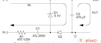
This is a particularly simple circuit, which can hardly even be called a circuit, since it uses only 2 components. This is a powerful diode and fuse. This option is quite viable and is even used on an industrial scale.
Power from the charger is supplied to the battery through the fuse. The fuse is selected based on the maximum charging current. For example, if the current is 10 A, then a 12-15 A fuse is needed.
The diode is connected in parallel and is closed during normal operation. But if the polarity is reversed, the diode will open and a short circuit will occur.
And the fuse is the weak link in this circuit, which will burn out at the same moment. After this you will have to change it.
The diode should be selected according to the datasheet based on the fact that its maximum short-term current was several times greater than the fuse combustion current.
This scheme does not provide 100% protection, since there have been cases when the charger burned out faster than the fuse.
Test results
To obtain protection performance results, a series of operational amplifiers were tested using the IEC standard (IEC‑61000–4-2) for ESD immunity requirements. Table 4 shows which components are protected by which protection circuits. Despite the fact that the standard provides for testing with three impacts of an overvoltage pulse at a level of ±8 kV, all presented circuits (to ensure a sufficient technological margin for the degree of protection) were tested with 100 pulses of impact at a level of ±9 kV.
Table 4: List of devices and their associated protection configurations that have been tested to IEC-61000-4-2
| Name product | Main characteristics, bandwidth | Security elements | ||
| R, Ohm | C, pF | D, V_WM | ||
| AD823 | With input stage using field-effect transistors | 220 | 100 | |
| 16 MHz | 68 | 36 | ||
| ADA4077 | Low noise, precision | 220 | 100 | |
| 3.9 MHz | 68 | 36 | ||
| ADA4084 | Low noise | 220 | 100 | |
| 15.9 MHz | 68 | 36 | ||
| ADA4522 | Low noise, precision | 220 | 100 | |
| 2.7 MHz | 68 | 36 | ||
| ADA4528 | Low noise, precision | 220 | 100 | |
| 3 MHz | 68 | 36 | ||
| ADA4610 | Low noise, precision | 220 | 100 | |
| 15.4 MHz | 68 | 36 | ||
| ADA4622 | Low noise, precision | 220 | 100 | |
| 8 MHz | 68 | 36 | ||
| ADA4625 | Low noise, JFET | 220 | 100 | |
| 18 MHz | 68 | 36 | ||
| ADA4661 | Precision | 220 | 100 | |
| 4 MHz | 68 | 36 | ||
| LT1490 | Micropower | 220 | 100 | |
| 200 kHz | 68 | 36 | ||
| LT6016 | Low power, precision, OTT | 220 | 100 | |
| 3.2 MHz | 68 | 36 | ||
| LT6018 | Low noise, precision | 220 | 100 | |
| 15 MHz | 68 | 36 | ||
| LT1636 | Micropower, OTT | 220 | 100 | |
| 200 kHz | 220 | 36 | ||
| LT1638 | Micropower, OTT | 220 | 100 | |
| 1.1 MHz | 68 | 36 | ||
| LT1494 | Micro Power, Precision, OTT | 220 | 100 | |
| 100 Hz | 68 | 36 | ||
The IEC standard requires that the test pulse generator ground be connected to the amplifier ground via two 470 kΩ resistors in parallel with a 30 pF capacitor. The test setup used is made more rigid because the test signal generator ground was directly connected to the amplifier ground. For added authenticity, these results were also verified using the IEC grounding circuit described above. Keep in mind that amplifiers have very different internal structures - what works for the devices on this list may or may not work for others. It is recommended that if other operational amplifiers or other protection components are used, they are thoroughly tested first.
Protection components used:
- Resistors: ERJ-P6 series, size 0805, manufactured by Panasonic.
- Capacitors: ceramic, size 0805, dielectric C0G/NPO, rated operating voltage 100 V, manufactured by Yageo.
- TVS diodes: CDSOD323‑T36SC, manufactured by Bourns (bidirectional, 36 V, low leakage current, rated for ESD protection, electrical fast transients (bursts) and surge tolerant to relevant standards).
- Varistors for protection against static electricity discharges: multilayer varistors of the MLA series, size 0603, operating voltage 26 V, manufactured by Bourns.
How can you protect your chips from this looming threat?
As you can imagine, there are so many options that a simple solution cannot be applied to all likely situations. Below is a list of factors that will determine whether a REA component can withstand an electrical surge event or not. The list is divided into two groups: factors beyond our control that we cannot control, and factors that we not only can, but should control.
Factors we cannot control:
- Test waveform defined by IEC. The test generator's discharge current pulse effects on ESD immunity testing, electrical fast transient (burst) presentation, and surge test pulse effects all have completely different profiles, so they will exploit specific device weaknesses that they target differently. influence.
- The technological process and the technology of the component in question. Some chip technologies are more vulnerable to blocking than others. For example, CMOS processes are the most susceptible to blocking, but there are ways to mitigate this danger through careful design and dielectric material trench isolation technology (slit-insulated IC structure) used in many modern processes.
- Internal structure of the device. There are so many ways to design an IC that a protection design that works for one IC may not be useful for another. For example, many devices have timing circuits that turn on protection structures when a sufficiently fast signal is detected. That is, a device that will “survive” a static electricity discharge will “die” if you add sufficient capacitance to the site of impact. This answer is counterintuitive, but it is very important to understand: the problem is that the general method of protecting the circuit by using an RC filter may not solve the problem here, but may only make the problem worse.
Factors we can control:
- Layout of elements and wiring of connection circuits on a printed circuit board. The closer the radioelements are to the place where the overvoltage is applied, the higher the likelihood that they will receive a higher energy signal. This is because when an applied signal (in the form of current or voltage) travels along a trace on a printed circuit board, its energy is dissipated as electromagnetic radiation along its path. In addition, the energy of the overvoltage pulse turns into heat due to the resistance of its propagation path, is absorbed by parasitic capacitances, and part of the pulse energy reaches neighboring conductors through capacitive and inductive coupling.
- Protection circuit. This is where we can have the most significant impact on ensuring the survivability of our end device.
Understanding how to design a protection scheme as efficiently as possible will give us the above - exactly what we cannot control.
Operating principle of a thermistor
The critical values of the resistance/temperature relationship for motor protection sensors are defined in DIN 44081/DIN 44082.
The DIN curve shows the resistance in thermistor sensors as a function of temperature.
Compared to PTO, thermistors have the following advantages:
• Faster response due to lower volume and weight
• Better contact with the motor winding
• Sensors are installed on each phase
• Provide protection when the rotor is blocked
How do we know what to protect ourselves from?
While we understand the need to protect a system from electrical surges, the term “protection” is too broad to be useful when it comes to deciding how exactly we need to protect our system. That's why the IEC (International Electrotechnical Commission - an international non-profit organization for standardization in the field of electrical, electronic and related technologies) and many other organizations have done some very difficult work to find out what types of electrical surges we might encounter in real life and what their parameters are. , determining influences. We will focus on IEC standards because they cover applications across the broadest electronic market and the complexity of understanding them is the reason for writing this article.
Rice. 1. Discharge current shape of the test generator (contact discharge, test voltage 8 kV)
Table 1 lists three basic standards that define what types of electrical surges a system can encounter. While this article will discuss ESD protection in detail, we should have some understanding and knowledge of surge-causing conditions such as electrical fast transient (EFT) and voltage surges.
Rice. 2. Electrical fast transient voltages level 4, complying with IEC-61000-4-4 standard (GOST IEC 61000-4-4-2016)
Table 1. IEC technical standards and their analogues
| Standard/ GOST R | Standard name | Source of exposure | Source of exposure Characteristics of exposure | |
| IEC | GOST R | |||
| IEC 6100042/ GOST 30804.4.22013 | Electromagnetic compatibility (EMC). Part 42: Testing and measurement techniques. Electrostatic discharge immunity test | Electromagnetic compatibility of technical equipment. Resistance to electrostatic discharges. Requirements and test methods (as amended) | Electrostatic discharge | Single pulse exposure very high voltage, ultra-short duration |
| IEC 6100044/ GOST IEC 61000442016 | Electromagnetic compatibility (EMC). Part 44: Testing and measurement techniques. Electrical fast transient/burst immunity test, IDT | Electromagnetic compatibility (EMC). Part 44. Test and measurement methods. Electrical resistance test fast transient processes (bursts) | External switching components (for example, EMF surges self-induction from motors) | Repeated exposure short pulses high voltage |
| IEC 6100045/ GOST IEC 61000452017 | Electromagnetic compatibility (EMC). Part 45: Testing and measurement techniques. Surge immunity test, IDT | Electromagnetic compatibility (EMC). Part 45. Test and measurement methods. Stability test to voltage surge | Lightning strikes, transients in the power system (for example, from boost converters) | High voltage pulses, relatively large duration |
Rice. 3. Normalized surge current (8/20 µs) according to IEC-61000-4-5
In Fig. Figures 1–3 show examples of the shapes of impact overvoltage pulses established by the standards given in Table 1. And in Fig. Figure 4 shows a simplified diagram of a test generator used in accordance with IEC-61000-42 and its practical application.
Rice. 4. Simplified circuit diagram of the test generator used in accordance with the IEC-61000-4-2 standard and its practical application
What is susceptible to electrical overvoltage?
In general, anything that has some kind of electronics inside is subject to electrical overvoltage. Those parts that interact with the outside world are especially vulnerable, as they are likely to be the first to be affected by electrostatic discharge (ESD), the effects of a lightning strike, etc. In this regard, we are interested in system components such as USB -ports, analog inputs of oscilloscopes and even a charging port for the latest high-performance blenders based on Internet of Things (IoT) technology.