What is current strength?
Electric current is the ordered movement of charged particles inside a conductor with the obligatory presence of a closed circuit.
The appearance of current is due to the movement of electrons and free ions that have a positive charge.
As they move, charged particles can heat the conductor and have a chemical effect on its composition. In addition, the current can influence neighboring currents and magnetized bodies.
Current strength is an electrical parameter that is a scalar quantity. Formula:
I=q/t, where I is current, t is time, and q is charge.
It is also worth knowing Ohm's law, according to which current is directly proportional to U (voltage) and inversely proportional to R (resistance).
I=U/R.
There are two types of current - positive and negative.
Below we will consider what this parameter depends on, how to increase the current strength in the circuit, in the generator, in the power supply and in the transformer.
We will provide proven recommendations that will allow you to solve your problems.
What does current strength depend on?
To increase I in a circuit, it is important to understand what factors can influence this parameter. Here we can highlight the dependence on:
- Resistance. The smaller the parameter R (Ohm), the higher the current in the circuit.
- Voltages. Using the same Ohm's law, we can conclude that as U increases, the current strength also increases.
- Magnetic field strength. The larger it is, the higher the voltage.
- Number of coil turns. The greater this indicator, the greater U and, accordingly, the higher I.
- The power of the force that is transmitted to the rotor.
- Diameter of conductors. The smaller it is, the higher the risk of heating and burning out the supply wire.
- Power supply designs.
- The diameter of the stator and armature wires, the number of ampere-turns.
- Generator parameters - operating current, voltage, frequency and speed.
How to increase the current in a circuit?
There are situations when it is necessary to increase I, which flows in the circuit, but it is important to understand that measures need to be taken to protect electrical appliances; this can be done using special devices.
Let's look at how to increase the current using simple devices.
To complete the work you will need an ammeter.
Option 1.
According to Ohm's law, current is equal to voltage (U) divided by resistance (R). The simplest way to increase force I, which suggests itself, is to increase the voltage supplied to the input of the circuit, or to reduce the resistance. In this case, I will increase in direct proportion to U.
For example, when connecting a 20 Ohm circuit to a power source with U = 3 Volts, the current value will be 0.15 A.
If you add another 3V power source to the circuit, the total value of U can be increased to 6 Volts. Accordingly, the current will also double and reach a limit of 0.3 Amperes.
The power supplies must be connected in series, that is, the plus of one element is connected to the minus of the first.
To obtain the required voltage, it is enough to connect several power sources into one group.
In everyday life, constant U sources combined into one group are called batteries.
Despite the obviousness of the formula, practical results may differ from theoretical calculations, which is due to additional factors - heating of the conductor, its cross-section, the material used, and so on.
As a result, R changes towards an increase, which leads to a decrease in force I.
Increasing the load in the electrical circuit can cause overheating of the conductors, burnout, or even a fire.
That is why it is important to be careful when operating devices and take into account their power when choosing a cross-section.
The value of I can be increased in another way by reducing the resistance. For example, if the input voltage is 3 Volts and R is 30 Ohms, then a current of 0.1 Ampere passes through the circuit.
If you reduce the resistance to 15 Ohms, the current strength, on the contrary, will double and reach 0.2 Amperes. The load is reduced to almost zero during a short circuit near the power source, in this case I increases to the maximum possible value (taking into account the power of the product).
Resistance can be further reduced by cooling the wire. This effect of superconductivity has long been known and is actively used in practice.
To increase the current in a circuit, electronic devices are often used, for example, current transformers (as in welders). The strength of variable I in this case increases with decreasing frequency.
If there is active resistance in the AC circuit, I increases as the capacitance of the capacitor increases and the inductance of the coil decreases.
In a situation where the load is purely capacitive in nature, the current increases with increasing frequency. If the circuit includes inductors, the force I will increase simultaneously with the decrease in frequency.
Also read - how electric current acts on the human body.
Option 2.
To increase the current strength, you can focus on another formula, which looks like this:
I = U*S/(ρ*l). Here we only know three parameters:
- S—wire cross-section;
- l is its length;
- ρ is the electrical resistivity of the conductor.
To increase the current, assemble a chain containing a current source, a consumer and wires.
The role of the current source will be performed by a rectifier, which allows you to regulate the EMF.
Connect the chain to the source, and the tester to the consumer (pre-set the device to measure current). Increase the EMF and monitor the indicators on the device.
As noted above, as U increases, it is possible to increase the current. A similar experiment can be done for resistance.
To do this, find out what material the wires are made of and install products that have lower resistivity. If you cannot find other conductors, shorten the ones already installed.
Another way is to increase the cross-section, for which it is worth mounting similar conductors parallel to the installed wires. In this case, the cross-sectional area of the wire increases and the current increases.
If we shorten the conductors, the parameter we are interested in (I) will increase. If desired, options for increasing the current can be combined. For example, if the conductors in the circuit are shortened by 50% and U is raised by 300%, then the force I will increase 9 times.
▍ DC-AC converter on Arduino
As a result of this failure, I thought that the indicators still need to be controlled somehow and I will most likely do all this using a microcontroller.
If this is so, then why shouldn’t the controller generate high voltage? Brilliant! Unlike the previous solution, which I spent several evenings on, this solution took me half an hour, including writing the code. To implement it, I unsoldered all the wires from the transformer, took a board from the Strela primary clock project and made a simple DC-AC converter from them. Essentially, with a frequency of 800 Hz, I alternately apply the rated voltage to the transformer windings in different directions. Please note that I apply 6.3 V to the winding and remove it from the high voltage winding. I posted the code on git so as not to clutter the article.
And this solution worked immediately, all my indicators were immediately lit on it.
Glow of e-paper, neon and ELI.
RMS voltage
(the one that the voltmeter measures) is even within the normal range: about 200 V (taking into account the losses in the transformer, a normal result). By the way, digital and analog voltmeters show different voltages; for this we had to acquire a pointer device.
Voltage measurements, voltmeter shows 200 V.
But the oscilloscope shows us a much more interesting picture. It turns out that our amplitude value is almost 400(!) volts!
This signal shape is not even due to the fact that the transformer filters the square wave, but rather because the L9110S driver chip does not work very well with an inductive load in pulse mode. Next I will show why this is so.
In fact, already at this stage it would be possible to end the article, they say - here is the solution for you. But I understand that not every reader will be able to go and buy the scarce incandescent transformer TN30-220-400, and the L9110S microcircuit is not the most suitable. Therefore, we will do everything wisely.
How to increase the current in the power supply?
On the Internet you can often come across the question of how to increase I in the power supply without changing the voltage. Let's look at the main options.
Situation No. 1.
A 12 Volt power supply operates with a current of 0.5 Amperes. How to raise I to its maximum value? To do this, a transistor is placed in parallel with the power supply. In addition, a resistor and stabilizer are installed at the input.
Find out more - how to check a transistor with a multimeter for serviceability.
When the voltage across the resistance drops to the required value, the transistor opens, and the rest of the current flows not through the stabilizer, but through the transistor.
The latter, by the way, must be selected according to the rated current and a radiator installed.
In addition, the following options are possible:
- Increase the power of all elements of the device. Install a stabilizer, a diode bridge and a higher power transformer.
- If there is current protection, reduce the value of the resistor in the control circuit.
Situation No. 2.
There is a power supply for U = 220-240 Volts (at the input), and at the output a constant U = 12 Volts and I = 5 Amperes. The task is to increase the current to 10 Amps. In this case, the power supply should remain approximately the same dimensions and not overheat.
Here, to increase the output power, it is necessary to use another transformer, which is converted to 12 Volts and 10 Amps. Otherwise, the product will have to be rewound yourself.
In the absence of the necessary experience, it is better not to take risks, because there is a high probability of a short circuit or burnout of expensive circuit elements.
The transformer will have to be replaced with a larger product, and the damper chain located on the DRAIN of the key will also have to be recalculated.
The next point is replacing the electrolytic capacitor, because when choosing a capacitance you need to focus on the power of the device. So, for 1 W of power there are 1-2 microfarads.
It is also recommended to change the diodes with rectifiers. In addition, it may be necessary to install a new rectifier diode on the low side and increase the capacitor capacity.
After such a modification, the device will heat up more, so installing a fan is not necessary.
Powerful power supply by upgrading from smaller power units
Progress does not stand still. Computer performance is growing rapidly. And as productivity increases, energy consumption also increases. If previously almost no attention was paid to the power supply, now, after nVidia announced the recommended power supply for its top solutions at 480 W, everything has changed a little. Yes, and processors consume more and more, and if all this is properly overclocked... I have long accepted the annual upgrade of the processor, motherboard, memory, video as inevitable. But for some reason, upgrading the power supply makes me really nervous. If hardware progresses dramatically, then there are practically no such fundamental changes in the circuitry of the power supply. Well, a larger trans, thicker wires on the chokes, more powerful diode assemblies, capacitors... Is it really impossible to buy a more powerful power supply, so to speak for growth, and live in peace for at least a couple of years. Without thinking about such a relatively simple thing as high-quality power supply.
It would seem simpler, buy the highest power power supply you can find, and enjoy a quiet life. But it was not there. For some reason, all employees of computer companies are sure that a 250-watt power supply will be more than enough for you. And, what infuriates me most of all, they begin to peremptorily lecture and groundlessly prove that they are right. Then you reasonably notice that you know what you want and are ready to pay for it, and you need to quickly get what you are asking for and earn a legitimate profit, and not anger a stranger with your meaningless, unsupported persuasion. But this is only the first obstacle. Go ahead.
Let's say you find a powerful power supply, and then you see, for example, this entry in the price list
- Power Man PRO HPC 420W – 59 ue
- Power Man PRO HPC 520W – 123 ue
With a difference of 100 watts, the price has doubled. And if you take it with a reserve, then you need 650 or more. How much is it? And that is not all!
The vast majority of modern power supplies use the SG6105 chip. And its switching circuit has one very unpleasant feature - it does not stabilize the voltages of 5 and 12 volts, and the average value of these two voltages, obtained from a resistor divider, is supplied to its input. And it stabilizes this average value. Because of this feature, a phenomenon called “voltage imbalance” often occurs. Previously we used TL494, MB3759, KA7500 microcircuits. They have the same feature. I will quote from Mr. Korobeinikov’s
.
“...Voltage imbalance occurs due to uneven load distribution across the +12 and +5 Volt buses. For example, the processor is powered from the +5V bus, and the hard drive and CD drive are on the +12 bus. The +5V load is many times greater than the +12V load. 5 volts fails. The microcircuit increases the duty cycle and +5V rises, but +12 increases even more - there is less load. We get a typical voltage imbalance..."
On many modern motherboards, the processor is powered by 12 volts, then the reverse skew occurs, 12 volts goes down, and 5 volts goes up.
And if in nominal mode the computer operates normally, then during overclocking the power consumed by the processor increases, the skew increases, the voltage decreases, the power supply's undervoltage protection is triggered and the computer turns off. If there is no shutdown, then the reduced voltage still does not contribute to good acceleration.
So, for example, it happened to me. I even wrote a note on this topic - “Overclocker's light bulb.” Then I had two power supplies working in my system unit - Samsung 250 W, Power Master 350 W. And I naively believed that 600 watts was more than enough. Enough may be enough, but the skew makes all those watts useless. I unknowingly enhanced this effect by connecting the motherboard from the Power Master, and the screw, disk drives, etc. from the Samsung. That is, it turned out that basically 5 volts are taken from one power supply, and 12 from the other. And the other lines are “in the air,” which intensified the “skew” effect.
announcements and advertising
RTX 3070 Ti Aorus at a non-Ti price
RTX 3080 for 288 tr in Citylink
RTX 3090 MSI for 539 TR
Earn money by participating in the content of our site
Another 3080 is even cheaper - see the price
Cool 3060 Ti Gigabyte Aorus fell in price 2 times
After that I purchased a 480 watt Euro case power supply. Due to my passion for silence, I converted it to fanless, which I also wrote about on the pages of the site. But this block also contained SG6105. When testing it, I also encountered the phenomenon of “voltage imbalance”. The power supply you just purchased is not suitable for overclocking!
And that is not all! I still wanted to buy a second computer and keep the old one “for experiments,” but the toad simply “pressed.” Recently, I finally persuaded this beast and purchased hardware for a second computer. This is, of course, a separate topic, but I bought a power supply for it - PowerMan Pro 420 W. I decided to check it for “distortion”. And since the new mother powers the processor via a 12-volt bus, I checked using it. How? You will find out if you read the article to the end. In the meantime, I’ll say that with a load of 10 amperes, twelve volts dropped to 11.55. The standard allows voltage deviation of plus or minus 5 percent. Five percent of 12 is 0.6 volts. In other words, at a current of 10 amperes, the voltage dropped almost to the maximum permissible level! And 10 amperes corresponds to 120 watts of processor consumption, which is quite realistic when overclocked. The datasheet for this unit states a current of 18 amperes on the 12 volt bus. I think I won’t see these amperes, since the power supply will turn off much earlier due to the “distortion”.
Total - four power supplies in two years. And should I take the fifth, sixth, seventh? No, enough. Tired of paying for something you don't like in advance. What’s stopping me from making a kilowatt power supply myself and living in peace for a couple of years, with confidence in the quality and quantity of my pet’s food. In addition, I started making a new case. I started making the case huge and the power supply, a non-standard size, should fit there without any problems. But owners of standard cases may also find this solution useful. You can always make an external power supply, especially since there are already precedents. It seems Zalman has released an external power supply.
Of course, making a power supply of such power from scratch is difficult, time-consuming, and troublesome. That's why the idea came up to assemble one block from two factory ones. Moreover, they already exist and, as it turned out, in their current form they are unsuitable for overclocking. This idea was prompted by the same article by Mr. Korobeinikov
.
“...To introduce separate stabilization, you need a second transformer and a second PWM chip, and this is done in serious and expensive server units...”
In a computer power supply there are three high-current lines with voltages of 5, 12 and 3.3 volts. I have two standard power supplies, let one of them produce 5 volts, and the other, more powerful, 12 and all the rest. The 3.3 volt voltage is stabilized separately and does not cause distortion. Lines producing -5, -12, etc. – are low-power and these voltages can be taken from any unit. And to carry out this activity, use the principle set out in the same article by Mr. Korobeinikov - disconnect unnecessary voltage from the microcircuit, and adjust the necessary one. That is, now SG6105 will stabilize only one voltage and, therefore, the phenomenon of “voltage imbalance” will not occur.
The operating mode of each power supply is also simplified. If you look at the power part of a typical power supply circuit (Fig. 2), you can see that the 12, 5 and 3.3 volt windings represent one common winding with taps. And if from such a trance we take not all three at once, but only one voltage, then the power of the transformer will remain the same, but for one voltage, and not three.
For example, a unit produced 250 watts along lines of 12, 5, 3.3 volts, but now we will get almost the same 250 watts through a line, for example, 5 volts. Whereas previously the total power was divided between three lines, now all the power can be obtained on one line. But in practice, this requires replacing the diode assemblies on the line used with more powerful ones. Or include in parallel additional assemblies taken from another block on which this line will not be used. Also, the maximum current will limit the cross-section of the inductor wire. The power supply's overload protection may also work (although this parameter can be adjusted). So we won’t get completely tripled power, but there will be an increase, and the units will heat up much less. You can, of course, rewind the inductor with a larger cross-section wire. But more on that later.
Before we begin to describe the modification, we need to say a few words. It's very difficult to write about electronic equipment refurbishments. Not all readers understand electronics, not everyone reads circuit diagrams. But at the same time, there are readers who deal with electronics professionally. No matter how you write it, it turns out that for some it is incomprehensible, but for others it is irritatingly primitive. I will still try to write in a way that would be understandable to the vast majority. And the experts, I think, will forgive me.
It is also necessary to say that you make all modifications to the equipment at your own peril and risk. Any modifications will void your warranty. And of course, the author is not responsible for any consequences. It would not be amiss to say that a person undertaking such a modification must be confident in his abilities and have the appropriate tool. This modification is possible on power supplies based on the SG6105 chip and slightly outdated TL494, MB3759, KA7500.
First, I had to look for the datasheet for the SG6105 chip - it turned out to be not that difficult. I quote from the datasheet the numbering of the legs of the microcircuit and a typical connection diagram.
Figure 1. SG6105
Rice. 2. Typical connection diagram.
Rice. 3. Connection diagram SG6105
I will first describe the general principle of modernization. First, upgrading the units to SG6105. We are interested in pins 17(IN) and 16(COMP). The resistor divider R91, R94, R97 and the trimming resistor VR3 are connected to these pins of the microcircuit. On one block we turn off the 5 volt voltage; to do this we unsolder the resistor R91. Now we adjust the voltage value of 12 volts with resistor R94 roughly, and with variable resistor VR3 precisely. On the other block, on the contrary, we turn off 12 volts, for this we unsolder the resistor R94. And we adjust the voltage value to 5 volts roughly with resistor R91, and precisely with variable resistor VR3.
The PC – ON wires of all power supplies are connected to each other and soldered to a 20-pin connector, which we then connect to the motherboard. It's more difficult with the PG wire. I took this signal from a more powerful power supply. In the future, you can implement several more complex options.
Rice. 4. Connector wiring diagram
Now about the features of upgrading units based on the TL494, MB3759, KA7500 microcircuits. In this case, the feedback signal from the 5 and 12 volt output rectifiers is supplied to pin 1 of the microcircuit. We do it a little differently - we cut the printed circuit board track near pin 1. In other words, we disconnect pin 1 from the rest of the circuit. And we apply the voltage we need to this pin through a resistor divider.
Fig 5. Circuit diagram for TL494, MB3759, KA7500 microcircuits
In this case, the resistor values are the same for stabilizing 5 volts and 12 volts. If you decide to use a power supply to obtain 5 volts, then connect the resistor divider to the 5V output. If for 12, then by 12.
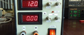
Probably enough theory and it’s time to get down to business. First you need to decide on the measuring instruments. To measure voltages, I will use one of the cheapest multimeters, DT838. Their voltage measurement accuracy is 0.5 percent, which is quite acceptable. To measure current I use a dial ammeter. The currents need to be measured are large, so you will have to make an ammeter yourself from a dial measuring head and a homemade shunt. I could not find a ready-made ammeter with a factory-made shunt of an acceptable size. I found a 3 amp ammeter and took it apart. I pulled the shunt out of him. The result was a microammeter. Then there was a little difficulty. To make a shunt and calibrate an ammeter made from a microammeter, an exemplary ammeter was needed that could measure current in the range of 15-20 amperes. For these purposes, it would be possible to use current clamps, but I didn’t have any. I had to look for a way out. I found the simplest solution, of course, not very accurate, but quite enough. I cut the shunt from a steel sheet 1mm thick, 4mm wide and 150mm long. I connected 6 12V, 20W light bulbs to the power supply via this shunt. According to Ohm's law, a current equal to 10 amperes flowed through them.
P(Wt)/U(V)=I(A), 120/12=10A
One wire from the microammeter was connected to the end of the shunt, and the second was moved along the shunt until the arrow of the device showed 7 divisions. The length of the shunt was not enough to reach 10 divisions. It was possible to cut the shunt thinner, but due to lack of time I decided to leave it as is. Now 7 divisions of this scale correspond to 10 amperes.
Photo 1 Budget stand for shunt selection. Photo 2. Stand with 6 12 volt 20 watt light bulbs turned on.
The last photo shows how the voltage of 12 volts dropped at a current of 10 amperes. Power supply PowerMan Pro 420 W. It shows minus 11.55 due to the fact that I mixed up the polarity of the probes. In fact, of course, plus 11.55. I will use the same stand as a load to adjust the finished power supply.
I will make a new power supply based on the PowerMaster 350 W, it will produce 5 volts. According to the sticker on it, it should deliver 35 amps along this line. And PowerMan Pro 420 W. I will take all other voltages from it.
In this article I will show the general principle of modernization. In the future, I plan to convert the resulting power supply into a passive one. Perhaps I'll rewind the chokes with a wire of a larger cross-section. I will modify the connecting cables to reduce interference and ripple. I will monitor currents and voltages. And much more is possible. But that's in the future. I will not describe all this in this article. The purpose of the article is to prove the possibility of obtaining a powerful power supply by upgrading two or three units of lower power.
A little about safety precautions. All soldering is carried out, naturally, with the unit turned off. After each shutdown of the unit, before further work, discharge large capacitors. They have a voltage of 220 volts, and they accumulate a very decent charge. Not fatal, but extremely unpleasant. Electrical burns take a long time to heal.
I'll start with PowerMaster. I disassemble the unit, take out the board, cut off the extra wires...
Photo 3. PowerMaster 350 W unit
I find a PWM chip, it turns out to be TL494. I find pin 1, carefully cut the printed circuit conductor and solder a new resistor divider to pin 1 (see Fig.5). I solder the input of the resistor divider to the five-volt output of the power supply (usually these are red wires). I check once again that the installation is correct, this is never superfluous. I connect the modernized unit to my budget stand. Just in case, hiding behind a chair, I turn it on. There was no explosion and this even caused slight disappointment. To start the unit, I connect the PS ON wire to the common wire. The unit turns on and the lights come on. First victory.
Using variable resistor R1 at a low load of the power supply (two light bulbs 12V, 20W and spot 35W), I set the output voltage to 5 volts. I measure the voltage directly at the output connector.
My camera is not the best, I can’t see small details, so I apologize for the quality of the pictures.
The power supply can be turned on without a fan for a short time. But you need to monitor the temperature of the radiators. Be careful, there is voltage, sometimes high voltage, on the radiators of some power supply models.
Without turning off the unit, I begin to connect an additional load - light bulbs. The voltage does not change. The block stabilizes well.
In this photo, I connected all the light bulbs that were available to the block - 6 lamps of 20w, two of 75w, and a spot of 35w. The current flowing through them according to the ammeter readings is within 20 amperes. No “sagging”, no “distortions”! Half the battle is done.
Now I take on the PowerMan Pro 420 W. I also disassemble it.
I find the SG6105 chip on the board. Then I look for the necessary conclusions.
The circuit diagram given in Mr. Korobeinikov’s article corresponds to my block, the numbering and resistor values are the same. To turn off 5 volts, I unsolder the resistor R40 and R41. Instead of R41, I solder two variable resistors connected in series. Nominal 47 kOhm. This is for rough adjustment of the 12 volt voltage. For precise adjustment, use resistor VR1 on the power supply board
Fig 6. Fragment of the PowerMan power supply circuit
Again I take out my primitive stand and connect the power supply to it. First I connect the minimum load - 35W spot.
I turn it on and adjust the voltage. Then, without turning off the power supply, I connect additional light bulbs. The voltage does not change. The block works great. According to the ammeter readings, the current reaches 18 amperes and there is no voltage drop.
The second stage is completed. Now it remains to check how the blocks will work in pairs. I cut the red wires going from the PowerMan to the connector and Molex, and insulate them. And I solder a five-volt wire from the PowerMaster 350 W to the connector and molex, and also connect the common wires of both units. I combine the Power On wires of the power supplies. I'll take PG from PowerMan. And I connect this hybrid to my system unit. He looks a little strange, and if anyone wants to know more about him, please contact me on PS.
The configuration is like this:
- Mother Epox KDA-J
- Processor Athlon 64 3000
- Memory Digma DDR500, two 512Mb sticks
- Samsung 160Gb screw
- Video GeForce 5950
- DVD RW NEC 3500
I turn it on, everything works great.
The experience was a success. Now you can begin further modernization of the “integrated power supply”. Converting it to passive cooling. The photo shows a panel with instruments - everything will be connected to this unit. Pointer instruments - current monitoring, digital instruments in round holes under the pointer - voltage monitoring. Well, the tachometer and all that, I already wrote about this on my personal account. But that's for later.
I did not check the effect of the “combined power supply” on further overclocking. I'll finish it and check it then. The processor has already been overclocked to 2.6 gigahertz on the bus, with a processor voltage of 1.7 volts. I ran it on a fanless power supply, but with such overclocking, the 12 volts on it dropped to 11.6 volts. And the hybrid produces exactly 12. So, perhaps I’ll squeeze a few more megahertz out of it. But that will be a different story.
List of used literature:
- datasheet for SG6105 chip
- Article by Mr. Korobeinikov
- Radio magazine. – 2002.-No. 5, 6, 7. “Circuit design of power supplies for personal computers” ed. R. Alexandrov
We look forward to your comments in a specially created conference thread.
How to increase the current in the charger?
When using chargers, you may notice that chargers for a tablet, phone or laptop have a number of differences. In addition, the speed at which devices are charged may also vary.
Here a lot depends on whether an original or non-original device is used.
To measure the current that goes to your tablet or phone from the charger, you can use not only an ammeter, but also the Ampere app.
Using the software, it is possible to determine the charging and discharging speed of the battery, as well as its condition. The application is free to use. The only drawback is advertising (the paid version does not have it).
The main problem with charging batteries is the low current of the charger, which is why the time to gain capacity is too long. In practice, the current flowing in the circuit directly depends on the power of the charger, as well as other parameters - cable length, thickness and resistance.
Using the Ampere application, you can see at what current the device is charged, and also check whether the product can charge at a higher speed.
To use the capabilities of the application, just download it, install and run it.
After this, the phone, tablet or other device is connected to the charger. That's all - all that remains is to pay attention to the current and voltage parameters.
In addition, you will have access to information about the battery type, U level, battery condition, as well as temperature conditions. You can also see the maximum and minimum I that occur during the cycle.
If you have several chargers at your disposal, you can run the program and try charging each of them. Based on the test results, it is easier to select a charger that provides the maximum current. The higher this parameter is, the faster the device will charge.
Current measurement isn't the only thing Ampere can do. With its help, you can check how much I is consumed in standby mode or when turning on various games (applications).
For example, after turning off the display brightness, deactivating GPS or data transfer, it is easy to notice a decrease in load. Against this background, it is easier to conclude which options drain the battery the most.
What else is worth noting? All manufacturers recommend charging devices with “native” chargers that produce a certain current.
But during operation, there are situations when you have to charge your phone or tablet with other chargers that have more power. As a result, the charging speed may be higher. But not always.
Few people know, but some manufacturers limit the maximum current that the device’s battery can accept.
For example, a Samsung Galaxy Alpha device comes with a 1.35 Ampere charger.
When connecting a 2-amp charger, nothing changes - the charging speed remains the same. This is due to a limitation set by the manufacturer. A similar test was carried out with a number of other phones, which only confirmed the guess.
Taking into account the above, we can conclude that non-native chargers are unlikely to cause harm to the battery, but can sometimes help with faster charging.
Let's consider another situation. When charging a device via a USB connector, the battery gains capacity more slowly than when charging the device from a conventional charger.
This is due to the limitation of the current that a USB port can supply (no more than 0.5 Ampere for USB 2.0). When using USB3.0, the current increases to 0.9 Ampere.
In addition, there is a special utility that allows the “troika” to pass a larger I through itself.
For devices like Apple, the program is called ASUS Ai Charger, and for other devices - ASUS USB Charger Plus.
Clock on IV-11 diagram
Below is a diagram of a tube clock using vacuum-luminescent indicators IV-11:
To power the indicators, I assembled a high-frequency push-pull pulse converter on a specialized microcircuit CD4047B (DD1), the microcircuit controls the assembly of field-effect transistors DD2, which switch the pulse transformer T1. The transformer is wound on a ferrite ring, 13 mm in diameter, cross-section 6 by 3 mm. All windings have a tap from the middle, the primary winding contains 14 turns, the secondary winding contains 2 turns, with a 0.4 mm wire. The secondary anode winding is 140 turns, 0.2 mm wire. Winding is not difficult when using a special shuttle. The generator frequency is 50 kHz. The total filament voltage was 1.42V according to the oscilloscope, the anode voltage relative to the middle terminal was about 50V.
To prevent the segments from glowing in the absence of a control voltage, you need to apply a negative bias to the grid relative to the cathode. This can be realized by a positive bias of the filament voltage relative to the common wire. For this purpose, a VD3 zener diode is installed in the circuit, connected to the middle terminal of the filament winding; an anode voltage is applied to the zener diode cathode through a resistor to obtain a bias.
To switch the anodes of the segments and the grid, I used specialized high-voltage drivers TD62783AP (DA1, DA2), maximum switched voltage 50V.
In general, another control scheme is often found: a negative bias equal to the anode voltage is applied to the cathode, while the anode segments and grids are switched using bipolar pnp transistors to a common wire. I didn’t want to solder a bunch of transistors and complicate the printed circuit board, so I used drivers, as mentioned above.
PIC16F876A was chosen as the DD3 control microcontroller, since many lines were required to connect all components. The program is written in assembler.
The popular DS3231 module is used as a real-time clock, in which you need to unsolder a resistor that supplies external power to the battery, as well as an LED, and you can also unsolder the memory chip.
To enable time synchronization, I used the u-blox NEO-6mv2 GPS module; there was already an article on the site dedicated to this module. Using transistor VT3, the microcontroller controls the power supply to the GPS module. To establish communication with the microcontroller, the module must have the following port settings: baud rate 9600 bits per second, 8 data bits, 1 stop bit. By default, the module is usually supplied with exactly these settings; if this is not the case, you need to change the port parameters through the special u-center program, connecting the module to the computer via a USB-UART adapter.
I additionally added a photoresistor R14 to the clock circuit on the IV-11, and implemented in the microcontroller program automatic adjustment of the brightness of the indicators, depending on the lighting. Brightness is adjusted by changing the duty cycle.
LED HL1 is a separator of hours and minutes; it blinks while the time is displayed; LEDs HL2-HL5 are installed to illuminate the indicators. The alarm buzzer has a built-in oscillator, a regular buzzer will not make a sound. Due to the lack of microcontroller pins, only two buttons had to be left to set the clock.
The clock is mounted on two single-sided printed circuit boards; the indicators, photoresistor and LEDs are located on a separate board, which is inserted into the main board using connectors.
Drivers DA1, DA2 can be replaced with KID65783AP, UDN2981A-UDN2984A, M54563P. Field-effect transistor VT3 can be replaced with IRLML2244, IRLML6402, etc., assembly of field-effect transistors DD2 with IRF7311, IRF7341, IRF7351, diodes VD1, VD2 with HER107-HER108, STTH110.
How to increase the current in a transformer?
Another question that worries electronics enthusiasts is how to increase the current strength in relation to the transformer.
Here are the following options:
- Install a second transformer;
- Increase the diameter of the conductor. The main thing is that the cross-section of the “iron” allows it.
- Raise U;
- Increase the cross-section of the core;
- If the transformer operates through a rectifier device, it is worth using a product with a voltage multiplier. In this case, U increases, and with it the load current also increases;
- Buy a new transformer with a suitable current;
- Replace the core with a ferromagnetic version of the product (if possible).
A transformer has a pair of windings (primary and secondary). Many output parameters depend on the wire cross-section and the number of turns. For example, there are X turns on the high side and 2X on the other side.
This means that the voltage on the secondary winding will be lower, as will the power. The output parameter also depends on the efficiency of the transformer. If it is less than 100%, U and the current in the secondary circuit decrease.
Taking into account the above, the following conclusions can be drawn:
- The power of the transformer depends on the width of the permanent magnet.
- To increase the current in the transformer, a decrease in R load is required.
- The current (A) depends on the diameter of the winding and the power of the device.
- In case of rewinding, it is recommended to use thicker wire. In this case, the wire mass ratio on the primary and secondary windings is approximately identical. If you wind 0.2 kg of iron on the primary winding and 0.5 kg on the secondary winding, the primary will burn out.
How to increase the current in the generator?
The current in the generator directly depends on the load resistance parameter. The lower this parameter, the higher the current.
If I is higher than the nominal parameter, this indicates the presence of an emergency mode - frequency reduction, generator overheating and other problems.
For such cases, protection or disconnection of the device (part of the load) must be provided.
In addition, with increased resistance, the voltage decreases, and U increases at the generator output.
To maintain the parameter at an optimal level, regulation of the excitation current is provided. In this case, an increase in the excitation current leads to an increase in the generator voltage.
The network frequency must be at the same level (constant).
Let's look at an example. In a car generator, it is necessary to increase the current from 80 to 90 Amperes.
To solve this problem, you need to disassemble the generator, separate the winding and solder the lead to it, followed by connecting the diode bridge.
In addition, the diode bridge itself is changed to a part with higher performance.
After this, you need to remove the winding and a piece of insulation in the place where the wire is to be soldered.
If there is a faulty generator, the lead is bitten off from it, after which the legs of the same thickness are built up using copper wire.
After soldering, the joint is insulated with heat shrink.
The next step is to buy an 8-diode bridge. Finding it is a very difficult task, but you have to try.
Before installation, it is advisable to check the product for serviceability (if the part is used, a breakdown of one or more diodes is possible).
After installing the bridge, attach the capacitor, and then a 14.5-volt voltage regulator.
You can purchase a pair of regulators - 14.5 (German) and 14 Volts (domestic).
Now the rivets are drilled out, the legs are unsoldered and the tablets are separated. Next, the tablet is soldered to a domestic regulator, which is fixed with screws.
All that remains is to solder the domestic “pill” to the foreign regulator and assemble the generator.
▍ Blocking generator
I had the highest hopes for this voltage source; it is very simple, miniature, and requires a minimum number of parts.
The only thing is that he needs a scarce TN30-220-400 transformer or needs to wind the transformer himself. Fortunately, we managed to find the transformer at a flea auction somewhere in Omsk. It all started with a comment from radiolok
... But the blocking generator can handle this quite well. I decided to take the TN30-220-400 transformer as a basis. 4 windings of 6.3V each will act as a primary, 13.5W of output power, the hardware is already designed for 400Hz.
There was an explanation below in the thread:
transistor T2 and then throw it out, put TN30-220-400 as Tr1. Of the 4 windings at 6.3V, we parallel three of them - this will be the main w2, the second - on the OS (w1) the former primary will become the secondary. The power will already be 5-6V.
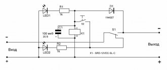
I will say right away that there was no point in combining the windings, this does not affect the operation of the circuit in any way (which is logical), and the current is limited by a resistor (R1 in the diagram below), and even in the worst case it will not exceed the rated current of one winding. But I honestly tested this option, combining the windings, then disconnecting them (well, we need to test the hypothesis). In order not to confuse the reader, I will give another, more visual diagram from the same book by A.V. Kasimenko “Electroluminescent alphanumeric indicators.”
My supply voltage is adjustable. Resistor R1 limits the current that flows through the transformer winding and the transistor. Resistor R2 and capacitor C determine the period of operation of this generator, according to the following formula (from the same book):
Thus, the frequency is: If we take resistor R2 = 50k, leave the capacitor the same, then as a result we get a frequency of 400 Hz, as we need.
When I was selecting a transistor, I didn’t bother too much, I opened a well-known website and chose the first NPN transistor that caught my eye, 140 MHz, 160 V, 1.5 A - 2SB649AC
.
I would like to note one point that the above book uses homemade transformers with certain parameters, and not factory-made solutions. In general, winding a transformer is no problem, you just need time and patience. However, I have neither ferrite, nor winding wire, nor patience, so I decided to make do with what I have.
I will give a diagram of the transformer TN30-220-400
. Pay attention to the points in the blocking oscillator circuit from the book, and to the points in the transformer circuit. If you turn them on in antiphase, it will not work.
Transformer circuit.
Winding 3-4 acted as winding W1, winding 5-6 acted as winding W2. Secondary winding W3, respectively 1-2. At the output of the winding I installed a current-limiting resistor of 1 kOhm.
We assemble the entire circuit on a breadboard and carry out tests. No matter how much I struggled, with the parameters of resistor R2 and capacitor giving 400 Hz, I was unable to ignite a single segment of the ELI, only broken single points sometimes ignited. The only thing that managed to somehow light up was a neon light bulb.
The neon lamp glows faintly.
Single pulses are visible, the period between them is actually 400 Hz, but there is a very long period of just silence. As I understand it, this is determined by the inductance of the winding, because the parameters of the resistor-capacitor determined only the frequency of the pulses. After fiddling around with this simple circuit for several evenings, I came up with a rating of R2 = 10 kOhm (as in the circuit from the book in this post) - this is the 20 kHz frequency that the generator produces, and it is at the frequency limit of the transformer’s bandwidth. With these values, I even managed to light the IN-12A indicator lamp.
The oscillogram of the received signal is as follows (the divisor is 1:10).
In fact, a separate article could be written about just one blocking generator, with a bunch of measurements, oscillograms and other things. But I didn’t get any reasonable results from it, despite the simplicity of the solution. Most likely the transformer is not suitable for this task, perhaps I did something wrong. In any case, the output current is incredibly low, and the voltage sags from any minimal load, even such as a single segment
IEL.