What is an element such as a capacitor? This is a small radio element with a concentrated electrical capacitance formed by two or more electrodes. In some cases, this element is also called the lining. These small parts are separated by a thing called a dielectric (special paper, a thin layer of mica, ceramic, etc.). The capacity of this part will depend on indicators such as the size (area) of the plates, the distance between these elements, as well as on the properties of the dielectric itself.
general information
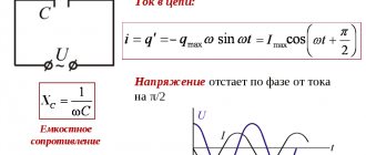
A very important fact. A capacitor has one property that manifests itself in an alternating current circuit. For such a circuit, this part will be a resistance, the value of which will depend on the frequency. If the frequency increases, the resistance will decrease, and vice versa.
There are basic units of measurement with which you can determine the identity of a particular capacitor. These include Farad, microFarad, etc. The designation on the elements of these units, respectively, is: F, μF.
Variable capacitor: description, device and diagram
What is an element such as a capacitor? This is a small radio element with a concentrated electrical capacitance formed by two or more electrodes. In some cases, this element is also called the lining. These small parts are separated by a thing called a dielectric (special paper, a thin layer of mica, ceramic, etc.). The capacity of this part will depend on indicators such as the size (area) of the plates, the distance between these elements, as well as on the properties of the dielectric itself.
Variable Capacitance Cells
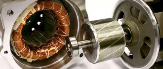
A variable capacitor has parts such as sections of plates made of metallic material. One of these sections can move smoothly in relation to the second. During this movement, it happens that the plates of the moving part, that is, the rotor, are most often inserted into the gaps existing between the plates of the stationary part, the stator. Thanks to this movement, the following happens. The area of overlap of one plate by another changes, as a result of which the capacitance of the variable capacitor also changes.
The dielectric in such elements is most often air. Although it is worth noting that, if we talk about equipment with small dimensions, for example, about transistor pocket receivers, then they often use variable capacitors with a solid dielectric. Wear-resistant and high-frequency raw materials are used as this element. Most often it is fluoroplastic or polyethylene.
Special forms of mechanically controlled capacitors
Various Shapes of Variable Capacitors
Multiple sections
Very often, several stator/rotor sections are located one behind the other on the same axis, allowing multiple tuned circuits to be configured using the same control element, such as a preselector, input filter, and corresponding oscillator in the receiver circuit. The sections may have the same or different capacitance ratings, for example 2 × 330 pF for the AM filter and oscillator, plus 3 × 45 pF for the two filters and oscillator in the FM section of the same receiver. Multi-section capacitors often include tuning capacitors connected in parallel with the variable sections, which are used to tune all tuned circuits to the same frequency.
Butterfly
And the capacitor is a butterfly
is a form of rotating variable capacitor with two independent sets of stator plates opposing each other, and a butterfly-shaped rotor positioned so that rotation of the rotor will equally change the capacitances between the rotor and either stator.
Butterfly capacitors are used in symmetrical tuned circuits, for example power amplifier stages in a push-pull configuration or symmetrical antenna tuners where the rotor must be kept "cold", i.e. connected to HF (but not necessarily DC) ground potential. Since peak high-frequency current typically flows from one stator to the other without passing through the wiper contacts, butterfly capacitors can handle large resonant high-frequency currents, such as into magnetic loop antennas.
In a butterfly capacitor, the stators and each rotor half can only cover a maximum angle of 90°, as there must be a non-overlapping rotor/stator position corresponding to the minimum capacitance, so turning only 90° covers the entire capacitance range.[1]
Split stator
Closely coupled split variable stator capacitor
does not have a 90° angle limitation because it uses two separate rotor electrode stacks positioned axially behind each other. Unlike a multi-section capacitor, the rotor plates in a split stator capacitor are mounted on opposite sides of the rotor axis. While a split stator capacitor has the benefits of larger electrodes compared to a butterfly capacitor, as well as a rotation angle of up to 180°, splitting the rotor plates introduces some losses since high-frequency current must pass through the rotor axis rather than passing directly through each . rotor blade.
Differential
Differential variable capacitors
also have two independent stators, but unlike a butterfly capacitor, where the capacitances on both sides increase equally as the rotor rotates, in a differential variable capacitor the capacitance of one section will increase and the capacitance of the other section will decrease, keeping the sum of the two stator capacitances constant. Consequently, differential variable capacitors can be used in capacitive potentiometric circuits.
KPI parameters
The main parameter for such parts, which will help determine the ability of the device to operate in an oscillatory circuit, has become the minimum and maximum capacitance. This indicator is most often indicated next to the variable capacitor itself on the device diagram.
It is worth noting that in devices such as radio receivers and radio transmitters, several oscillatory circuits are used at once. In order to configure the operation of several parts at once, capacitor blocks are used. One block most often consists of two, three or more KPI sections.
The rotor part for such units is usually mounted on one common shaft for all variable capacitors. This is done for convenience, since when just one rotor rotates, it becomes possible to change the capacity of all devices located in this section at once.
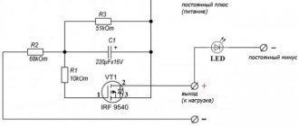
Limit continuous model of a pulsed capacitor capacitance control circuit
In the first part of the switching period K and K1tn< t< tn+t, the circuit is described by equation (6a). In the second part of the period tn+t< t< tn+1 = tn+T the DE system is valid:
where ki is the GT conversion coefficient [ki] = A/B = Ohm-1.
In vector-matrix form, this system of equations has the form:
- U = A2U + h2i, (9)
Where
Limit continuous model of the circuit Fig. 3a is described by the equation:
- U = AU + hi, (10)
Where
The DE system of the limiting continuous model of the system has the form:
Substituting (uC1–uC2), expressed from the second equation, into the first and taking into account that uC1 ~ uC2, we obtain with good accuracy:
Where
For kir = 1 we get
Seq = C1+ gC2. (12a)
Passing to the Laplace images in the vector-matrix equation (10) with zero initial conditions, we obtain:
Uab(p) = UC1(p) = cT-1hI(p),
where Uab(p) = UC1(p) = L{uC1(t)}, I(p) = L{i(t)} is the Laplace transform of uC1(t) and i(t), respectively, E is the unit 2× 2 matrix, cT = [1,0] - row vector.
From the last equation we obtain the transfer function of the limiting continuous model of the circuit in Fig. 3a:
Expanding W(p) into the sum of two simple fractions gives:
Where
According to (14), it is possible to construct an equivalent electrical circuit of the limiting continuous model, shown in Fig. 3b:
Moving on to Laplace images, we get:
Comparison of expressions (14) and (15) gives:
KPI schemes
It is important to note that in the diagram, each capacitor that is included in the block is displayed separately. In order to indicate that the capacitance of the variable capacitor of this block and the remaining elements can be changed by means of just one knob controlling the entire block, those arrows that indicate regulation should be connected by a single dashed line of mechanical connection.
It is worth noting that there are some varieties of such KPIs. One of the types is differential capacitors, which have found their application, for example, in the arms of capacitive bridges. A special feature of this type is that it has two rows of stator plates and one row of rotor plates. The arrangement of the groups of plates is as follows: when one group leaves the gap, the second immediately takes their place. At this moment, the capacitance of the differential type AC capacitor will decrease between the plates of the first stator group and the rotor group. But between the second group of stator plates and the rotor group, this figure will increase. Thus, the total value will remain unchanged all the time.
Adjustment KPIs
Another type of KPI is tuning capacitors. They are used to set the initial capacitance of the oscillating circuit, which will determine the maximum frequency of its tuning. The capacitance of the capacitor in an alternating current circuit of this type can be varied from several units of picoFarads to several tens of picoFarads. In some cases, higher capacity can be achieved.
The main requirement for these types of KPIs is the ability to smoothly change the capacity indicator. Also, this capacitor must ensure reliable fixation of the rotor in a given position.
What a capacitor is no longer
One common belief is that the main role of a capacitor is to store charge, much like a bucket of water is filled with one cup while being emptied by another.
If you've ever gotten into a debate about "does current flow through a capacitor" and gone more into politics than physics, you know that typical analogies don't make much sense when it comes to alternating current. A capacitor is simply two conductors separated by a dielectric, and nowhere in the basic physical explanations of its properties will you find an explanation of what to do about it.
Energy storage is just one of the many uses of a capacitor, such as filtering, shaping, and inverting electrical signals and impedances. We tend to think of this as the primary use of a capacitor, as it was its first use in the early days of direct current electricity and William Gilbert's electroscope, invented in the 15th century.
PDA design
The most common type of trimmer capacitor is ceramic. The design of this device is as follows. The base of the part is a ceramic stator, as well as a movable base mounted on it in the shape of a disk - the rotor. The plates in this element are thin layers of silver. They are applied by burning. Burning is carried out on the stator, as well as on the outer wall of the rotor.
In order to change or determine the capacitance of a variable capacitor of this type, it is necessary to rotate the rotor. If we talk about the simplest equipment, then it most often uses a wire tuning capacitor. This part consists of a piece of copper wire with a diameter of 1-2 mm. The length of this element is 15-20 mm. An insulated wire with a diameter of 0.2-0.3 mm is wound onto the wire very tightly, turn to turn. In order to change the capacitance in this device, it is necessary to unwind the wire. To prevent the winding from slipping off at this time, it is necessary to impregnate it with any insulating compound.
Resistance capacitance of a capacitor in an alternating current circuit
It is important to note here that current in a circuit in which there is a capacitor can only flow if the applied voltage changes. You also need to understand that the strength of the current that will circulate in the circuit during the discharge and charge of this element will be greater, the greater the capacitance of the capacitor itself, and will also depend on the speed at which changes in the electromotive force (EMF) occur.
One more property. A capacitor with variable capacitance, which is connected to a circuit with alternating current, will be a resistance for this circuit. In other words, the value of the capacitance resistance will be the smaller, the greater the value of the capacitance itself and the higher the frequency of the operating current. However, this statement is true only for a circuit in which the current is alternating. The capacitance of the capacitor is equal to infinity, that is, its resistance will be infinite if such an element is placed in a circuit with direct current.
Purpose of capacitors
A capacitor is a passive element of an electronic circuit consisting of two conductive plates, which are separated by some kind of dielectric.
Properties and functions performed
The main task of a capacitor is to accumulate a certain amount of electrostatic charge on the plates after connecting it to a live circuit. When the power is turned off, the capacitor retains the resulting charge.
- If the capacitor is connected to a closed circuit, but without power, or the voltage in it is lower than what is accumulated in the capacitor, then a complete or partial discharge of the element will occur, releasing the accumulated energy.
How to calculate capacitor capacity for alternating current
- Let us immediately introduce the concept of capacitance. In simple words, this is the amount of electrical energy that an element connected to the network can accumulate. This parameter is designated by the Latin letter “C”, and it is measured in Farads (F).
Interesting to know! High-capacity AC capacitors are capable of creating very powerful pulses when discharged quickly. They can be used, for example, in powerful photo flashes.
- The capacitance is calculated using the following formula: C=q/U, where q is the charge on one plate in Coulombs (the amount of energy passed through the conductor in 1 second at a current of 1 Ampere); and U – Voltage in Volts between shells.
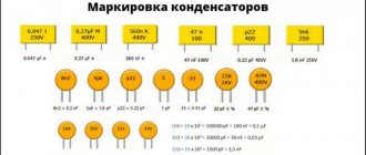
Capacitance designation in micro Farads
- The body of any capacitor contains data about its main parameters, including capacity. In the photo above it is highlighted in red, this is the designation. There you can also find out the operating voltage and temperature.
- Everything is simple, but it is worth considering that the indicated capacity is nominal, while its actual value can differ quite greatly, which is influenced by many factors.
- The capacitance of a capacitor can vary from units of picofarads to tens of farads, which depends on the area of the electrode (usually aluminum foil).
Interesting to know! To increase the useful capacity, the foil is rolled into rolls - this is how cylindrical capacitors are obtained.
Sectional view of a capacitor – layers of foil alternate with paper
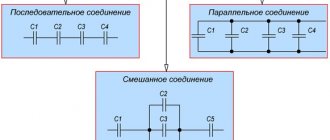
If the circuit requires a large capacitor capacity, then they are connected in parallel. In this case, the operating voltage is maintained, but the capacitance will increase in direct proportion, that is, it will be the sum of the capacitances of the connected capacitors.
Connections of capacitors in alternating current circuits: calculation of capacitance for series and parallel connections
If the capacitors are connected in series, the capacitance will not change; more precisely, it will be slightly less than the minimum capacitance included in the circuit. Why is such a connection needed? With it, the probability of breakdown of one of the capacitors is reduced to a minimum, that is, they seem to distribute the load.
- Capacitors are also characterized by such a parameter as specific capacitance. This is the direct ratio of the capacitance of an electrical part to the mass or volume of the dielectric. The maximum values of this parameter can be achieved with the smallest thickness of the dielectric spacer, however, to break down such a capacitor, a lower voltage is required, which we will talk about now.
- The part marking also indicates the voltage rating. Everything here is extremely simple - this value shows the maximum voltage level in the circuit at which the radio component can work out its entire service life without significantly changing its specified parameters.
- Hence the simple conclusion - the voltage on the capacitor should not exceed the nominal value, otherwise it may break through.
- The rated voltage level is affected by the materials from which the capacitor is assembled.
The concept of polarity for capacitors and their failure
Interesting to know! For many types of capacitors, the permissible voltage will decrease as it heats up, so the maximum operating temperature is also indicated on the product cases.
These capacitors failed without an explosion, this can be judged by the swollen lids of the barrels
Failure of capacitors is a very common failure in electrical engineering. They can “die” quietly, simply by swelling, or under the cannonade of a heavy explosion, flooding all nearby parts with electrolyte, under “stage smoke” and other effects.
That is why the failure of this element can be diagnosed purely visually, without the use of test equipment, but not always.
The capacitor could not withstand the load
Many electrolytic capacitors (with an oxide dielectric), due to the peculiarities of the interaction between the dielectric and the electrolyte, are capable of operating only if a certain polarity is observed, as indicated by the corresponding marking on the part body.
Different polarity symbols for capacitors
- When you try to connect them to a circuit in reverse polarity, the capacitors usually immediately fail - the dielectric is destroyed, the electrolyte boils, resulting in the same explosion.
- Capacitors explode quite often, especially in pulsed devices. This occurs due to overheating, leakage, or an increase in equivalent series resistance as the part ages.
- It is no secret that a damaged part in any circuit can be replaced with a new one, and the device will function as before, however, the consequences of an explosion can be quite serious - neighboring elements will be damaged, which will greatly complicate the repair, plus its price will increase.
To reduce the consequences, a valve is installed on the housings of large-capacity capacitors or a notch is made at the end in the form of the letters “X, K, and T.” Such capacitors explode very rarely, due to the fact that either the valve or the housing that has collapsed along the notch releases the electrolyte in the form of caustic fumes, that is, the pressure inside the housing decreases.
Other parameters
In addition to the parameters that we have already discussed, capacitors have inductance and their own resistance, so the circuit of a real capacitor can be represented as follows.
The structure of a capacitor, taking into account all its main parameters
These parameters can be called parasitic, since they interfere with the ideal operation of the part.
These include (denoted as in the diagram above):
- Capacitor insulation resistance (r) is a value determined by the ratio of the actual voltage applied to the capacitor to the leakage current.
- Equivalent series resistance (R) is the electrical resistance of the material from which the plates, capacitor leads and contacts with the board are made. It is also worth including losses in the dielectric. ESR begins to increase with increasing current frequency.
- Dielectric absorption . When a capacitor is quickly discharged when a load with low resistance is connected, if you remove the load, then, after some time, you can see that the voltage at the capacitor terminals will begin to slowly increase. This phenomenon is also called absorption of electric charge. How intensely this effect will manifest itself depends on the properties of the dielectric used in the capacitor.
Parasitic parameters also include the loss tangent and the temperature coefficient of the capacitance, but we won’t go that deep into the weeds in the introductory article.
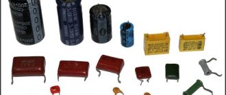
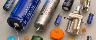
Types of capacitors
Capacitors are classified, first of all, by the type of dielectric used in them, which determines all the electrical parameters of the element.
Vacuum type condenser
- Vacuum capacitors - their structure is such that several coaxial cylinders, which are built into one, are located in an outer glass cylinder. These devices are characterized by the highest power per unit volume.
Air condenser for alternating current
- Air or gas condensers - there are constant and variable capacities. They are used mainly in electrical measuring equipment, radio receivers and transmitters, as they allow you to configure oscillatory circuits.
- Capacitors with liquid dielectric;
Ceramic single layer capacitor
- Capacitors with solid inorganic dielectrics - these include models based on glass enamels, glass ceramics, glass films, mica, ceramics, etc. Such capacitors are characterized by a very large capacitance, despite their modest dimensions.
Paper capacitor
- Capacitors with solid organic dielectrics – the variety here is also great: paper and metal-paper, film and combined.
Electric tantalum capacitor
- Separately, we can distinguish electrolytic and oxide-semiconductor capacitors, since they are distinguished by a large specific capacitance. They use an oxide layer around a metal anode as a dielectric. The second plate in it is either an electrolyte, in the first case, or a semiconductor, in the second. The anode, depending on the capacitor, can be made of tantalum, niobium or aluminum foil, as well as sintered powder.
This classification is not the only one and distinguishes between capacitors and, if possible, changing their capacitance:
- Constant capacitors are capacitors whose capacitance is constant throughout their service life, not counting changes associated with the aging of the part.
An air condenser can change its capacity
- Variables - this type is capable of changing its capacity while the equipment is operating. Such capacitors are controlled through mechanics, electrical voltage, and temperature.
Trimmer capacitors
- Trimming - the capacitance of these capacitors can also change, but this does not happen while the equipment is operating, but one-time, during installation or configuration. They are used mainly for leveling the initial capacitances of mating circuits, as well as for adjusting the parameters of circuit circuits.
Application of capacitors
Concluding the first part of the article, we cannot help but draw attention to the areas of application of these elements of electrical circuits. And they are used everywhere.
- They are combined with inductors and resistors to produce circuits in which the properties of the current depend on its frequency, such as a frequency filter or a tank feedback circuit.
- In systems that require the creation of a powerful pulse, which we have already mentioned today - camera flashes, pulsed lasers, Marx generators, etc.
- Capacitors are also used as memory elements, as they are able to retain a charge for quite a long time. The same property is used in devices designed to store energy.
- If we talk about industrial-level electrical engineering, capacitors are used to compensate reactive power and as filters for higher harmonics.
And this is not all areas, but we think that this is enough for now. Let's better move on to experiments and see what happens to the current when it passes through a capacitor.
Basic parameters for KPIs
There are several basic parameters for this type of capacitor.
One of the main ones is the law of change in capacitance. This law determines the nature of the change in capacitance. The change in this parameter will occur depending on the angle of rotation or on the linear movement of the moving part of the capacitor plates in relation to their stationary parts.
Another property is temperature stability. This indicator directly depends on the design of the capacitor itself. Most often, this indicator is positive, and for capacitors with air as a dielectric, the indicator does not exceed (200:300) 10-61/deg. If we talk about capacitors with a solid dielectric, then their value exceeds this indicator.
Basic quantities and units of measurement
There are several basic quantities that define a capacitor. One of them is its capacity (Latin letter C), and the second is the operating voltage (Latin letter U). Electrical capacitance (or simply capacitance) in the SI system is measured in farads (F). Moreover, as a unit of capacity, 1 farad is a lot - it is almost never used in practice. For example, the electrical charge of planet Earth is only 710 microfarads. Therefore, in most cases it is measured in quantities derived from farad: in picofarads (pF) with a very small capacitance value (1 pF = 1/10 6 μF), in microfarads (μF) with a sufficiently large value (1 μF = 1/ 10 6 F).
In order to calculate the electrical capacity, it is necessary to divide the amount of charge accumulated between the plates by the magnitude of the potential difference between them (voltage across the capacitor). The charge of the capacitor in this case is the charge accumulating on one of the plates of the device in question. On 2 conductors of the device they are the same in magnitude, but different in sign, so their sum is always zero. The charge on a capacitor is measured in coulombs (C) and is denoted by the letter Q.
Interesting read: operating principle and main characteristics of varistors.