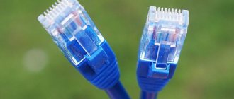
This article will talk about a network cable (Ethernet cable, or twisted pair, as many call it), thanks to which a computer connects to the Internet, a home local network is created, Internet telephony is carried out, etc.
In general, such a network cable in stores is sold by the meter and there are no connectors at its ends (plugs and RJ-45 connectors, which connect to the network card of a computer, router, modem and other devices. A similar connector is shown in the preview picture on the left). In this article I want to tell you how you can crimp such a cable if you want to create a local network at home yourself (or, for example, move a computer connected to the Internet from one room to another). Also, if your network disappears and after fixing the cable, it appears, I recommend taking the time to re-crimp the network cable.
The note! By the way, stores have already crimped cables with all connectors. True, they are of standard length: 2m, 3m, 5m, 7m. (m - meters). Also keep in mind that it is difficult to pull a crimped cable from one room to another - i.e. when you need to “stick” it through a hole in a wall/partition, etc.. You can’t make a large hole, and a connector won’t fit through a small one. Therefore, in this case, I recommend stretching the cable first and then crimping it.
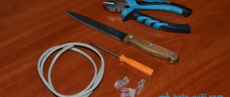
What do you need for work?
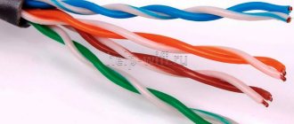
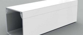
1. Network cable (also called twisted pair, Ethernet cable, etc.). Sold by the meter, you can buy almost any meter (at least for home use you can easily find it in any computer store). The screenshot below shows what such a cable looks like.
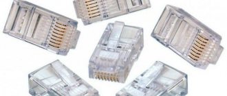
2. You will also need RJ45 connectors (these are connectors that are inserted into the network card of a PC or modem). They cost pennies, so buy them immediately with a reserve (especially if you haven’t dealt with them before).
3. Crimper. These are special crimping pliers with which RJ45 connectors can be crimped onto a cable in a matter of seconds. In principle, if you do not plan to pull Internet cables often, then you can borrow a crimper from friends, or do without it at all.
4. Knife and regular straight screwdriver. This is if you don’t have a crimper (which, by the way, has convenient “devices” for quickly cutting the cable). I don't think their photo is needed here?!
The question before crimping is: what and with what will we connect via the network cable?
Many people do not pay attention to more than one important detail. In addition to mechanical compression, there is also a little theory in this matter. The thing is that depending on what you connect and with what, how you need to crimp the Internet cable depends!
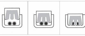
There are two types of connections: direct and cross. Below in the screenshots it will be clear and visible what we are talking about.
1) Direct connection
Used when you want to connect your computer to the router, TV to the router.
Important! If you connect one computer to another computer in this way, then your local network will not work! To do this, use a cross connection.
The diagram shows how to crimp the RJ45 connector on both sides of the Internet cable. The first wire (white and orange) is labeled Pin 1 on the diagram.
2) Cross connection
This circuit is used to crimp a network cable that will be used to connect two computers, a computer and a TV, and two routers to each other.
That is, first you decide what to connect to what, look at the diagram (in the 2 screenshots below, it’s not so difficult to figure this out even for beginners), and only then you start work (more about it, in fact, below)…
Crimping a network cable using pliers (crimper)
This option is simpler and faster, so I'll start with it. Then, I’ll say a few words about how this can be done using a regular screwdriver.
1) Trimming the shell
A network cable consists of: a hard shell, behind which are hidden 4 pairs of thin wires, which are surrounded by another insulation (multi-colored, which was shown in the last step of the article).
So, the first thing you need to do is trim the sheath (protective braiding), maybe by 3-4 cm at once. This will make it easier for you to distribute the wiring in the right order. By the way, it is convenient to do this with pliers (crimper), although some prefer to use a regular knife or scissors. In principle, they don’t insist on anything here, whatever is more convenient for you - the only important thing is not to damage the thin wiring hidden behind the shell.
The sheath is removed from the network cable by 3-4 cm.
Next, insert the protective cap into the network cable; doing this later will be extremely inconvenient. By the way, many people neglect these caps (and by the way, I do too). It helps to avoid unnecessary cable kinks and creates an additional “shock absorber” (so to speak).
3) Distribution of wiring and selection of circuit
Next, distribute the wiring in the order you require, depending on the selected scheme (this is discussed above in the article). After distributing the wires according to the desired pattern, trim them with pliers to about 1 cm (you can also trim them with scissors if you are not afraid of ruining them :)).
4) Inserting wires into the connector
Next, you need to carefully insert the network cable into the RJ45 connector. The screenshot below shows how to do this.
It is important to note that if the wires are not trimmed enough - they will stick out from the RJ45 connector, which is highly undesirable - any slight movement you make against the cable can disable your network and interrupt the connection.
How to connect a cable to RJ45: correct and incorrect options.
After this, carefully insert the connector into the pliers (crimper) and squeeze them. After this, our network cable is crimped and ready for use. The process itself is very simple and fast, there is nothing special to comment on here...
The process of crimping a cable in a crimper.
How to crimp a network cable using a screwdriver
This is, so to speak, a purely homemade manual method, which is useful for those who want to quickly connect computers, and not look for pliers. By the way, this is a feature of the Russian character; in the West people don’t do this without a special tool :).
1) Cable trimming
Everything is similar here (a regular knife or scissors can help).
Here you are also guided by the diagrams given above.
3) Inserting the cable into the RJ45 connector
Similarly (the same as in the case of crimping with a crimper (pliers)).
4) Fixing the cable and crimping it with a screwdriver
And here is the most interesting thing. After the cable is inserted into the RJ45 connector, place it on the table and press it and the cable inserted into it with one hand. With your other hand, take a screwdriver and carefully begin to press the contacts (picture below: red arrows show crimped and uncrimped contacts).
It is important here that the thickness of the end of the screwdriver is not too thick and you can press the contact all the way, securely fixing the wire. Please note that you need to fix all 8 wires (only 2 are fixed in the screenshot below).
After fixing the 8 wires, you need to fix the cable itself (the braid that protects these 8 “cores”). This is necessary so that when the cable is accidentally pulled (for example, it gets touched while being pulled), there is no loss of connection, so that these 8 cores do not fly out of their sockets.
This is done simply: fix the RJ45 connector on the table, and press on top with the same screwdriver.
This way you have a reliable and fixed connection. You can connect a similar cable to your PC and enjoy the network :).
By the way, an article on the topic of setting up a local network:
Source: pcpro100.info
Some terminology
“Networkers” use the term RJ-45 to refer to a connector for connecting local network nodes. In fact, a connector with this name does not officially exist.
This is what the most common plug in the world looks like
RJ-45S is usually understood as the standard by which modems are generally connected. In addition, it is the connectors of RJ standards that are designated something like this: 8P8C. By the way, this is the correct name of the connector, which is called RJ-45. And it is present in many standards: RJ-33X, RJ-61X and others. Interestingly, the official RJ-45S uses an 8P4C connector. The name encrypts the number of possible contacts and those involved. For example, 8P8C has 8 sockets, each with one contact. But 8P4C has only 4 contacts, although there are 8 sockets. However, when connecting, all physical contacts are not always used.
It is interesting that confusion in names occurs not only in Russia, but also abroad. 8P8C is called RJ-45 by specialists, shops, and sometimes even manufacturers. We will also join them and consider RJ-45 an 8P8C connector.
Network cable device
Different types of Internet cables have different structures. The simplest design is coaxial. The most advanced design of fiber optic wire.
Structure of a coaxial cable
Coaxial wire has a central core. A thick insulating layer is applied around it, with aluminum or copper braiding on top. General insulation is placed over the entire structure.
Twisted pair device
The optimal cable for the Internet is a twisted pair or Ethernet cable (as it is often called because of the plug of the same name at the end and the connector in the technology where the wire is connected). It is this that allows you to set up a local network between several devices, connect a printer to a computer, and connect the Internet from the supplier to the modem or router.
Such a wire is formed from two or four pairs of copper conductors (four-core and eight-core).
Inside each conductor there is one copper core with a diameter of 0.4-0.6 mm or many small wires. The first one is easier to crimp and is used to connect Internet sockets. The second is more flexible and is designed to connect PCs and other equipment.
Features of the optical cable structure
While users are often familiar with the structure of a twisted pair or coaxial wire, few know what a fiber optic network cable looks like from the inside.
The optical fiber inside consists of many tiny wires separated by a special coating. Each such wire has a silicon core through which these optical rays pass and carry. In addition to the core, it has an optical cladding, a buffer coating and protection.
The shell surrounding the core is made of glass. Light, reflected from it, is distributed throughout the core, but does not leave the wire.
What is twisted pair
Twisted pair with 8 cores
Twisted pair is a 4 or 8-core cable, the cores of which are woven together in pairs. Each pair of wires has similar colors, for example: yellow and yellow-white, red and red-white, etc. For each cable, special connectors are used - connectors, with 4 or 8 contacts, respectively.
There are several types of twisted pairs:
- UTP - twisted pair cables do not have shielding, and there is also no external shield. The most common type of cable for home Internet networks, when there are no long distances and interference.
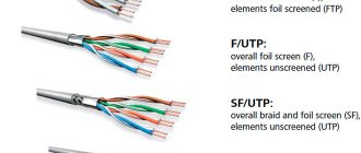
- FTP – no shielding, an external shield is present (foil). Such wires are used in office premises where interference occurs and data is transmitted over a distance of up to 100 m without loss of speed.
- STP - each pair has a wire-type protective screen, and there is also an external screen. Such cables are used in medium-sized offices and in rooms with interference. A high-quality signal is transmitted over a distance of up to 100 m.
- SF/UTP – the pairs themselves have no screens; the outer screen is double: a copper braid and a foil film. They are used in industrial enterprises to protect against interference and preserve a high-quality signal when transmitting over long distances.
- S/FTP - all pairs have a foil shield, external shielding is made of copper braid. They are used in buildings with high noise levels and in places where it is necessary to preserve the speed of data exchange over long distances.
Types of twisted pair
You should also pay attention to the color of the cable insulation. The most common is gray - standard insulation. Orange and red colors indicate that the cable insulation is made from non-flammable materials.
There are cables with 4 and 8 cores. Four-core cables are capable of transmitting data at speeds of no more than 100 Mbit/s. Eight-core ones can increase this speed to 1000 Mbit/s. For long cable routes (over 100 meters), installation of auxiliary amplifying equipment is required.
What is a lan cable? What is WAN. Why do you need a local network?
If you want to know what a WAN is, or how a WAN differs from a LAN, then you have come to the right place. Now let’s try to figure out what these technologies, connectors, connections are, what they are needed for and what the difference is.
I think that in most cases, when someone is looking for information on WAN, they mean the connector on the Wi-Fi router. After all, in almost every instruction for setting up a router you can find this abbreviation. Everyone writes about connecting some cables to WAN connectors, or LAN. Let's go in order:
WAN
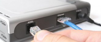
(Wide Area Network) is a global computer network. Simply put, this is the Internet. If we talk about the WAN connector, then this is the connector on the router into which the cable from the provider is connected. The network cable through which the router accesses the Internet.
On almost all routers this is a blue connector, and it looks like this:
In the photo above you can see that the connector is even labeled. Also, the router usually has an indicator of the connected WAN cable. During normal operation, it should blink actively. And next to the indicator itself they usually draw an icon in the form of a planet.
Now you know what WAN is. Let's take a closer look at how it differs from LAN.
What is the difference between a WAN connector and a LAN connector?
Everything here is also very simple. What is LAN?
LAN
(Local Area Network) is a local network. Simply put, these are computers that are connected to each other over a short distance. For example, computers, televisions, mobile devices that are connected to each other via a router within a home or office. This is a local network.
On routers you can usually find 4 LAN connectors. They are yellow and look like this:
They serve to connect devices to a local network via a network cable.
The difference between WAN and LAN is that WAN is access to the Internet, and LAN is a local network to which devices that are located close to each other can be connected.
I think that's all you need to know about these two designations. You can, of course, delve into technical aspects, abstruse definitions, etc., but this is unlikely to be of interest to anyone.
Questions often arise regarding what a twisted pair cable is. It is a type of cable that uses insulated conductors twisted in pairs. This type of cable is actively used in the telecommunications industry. It can be called an integral element of structured cable systems.
Obviously, the cable is so called based on the use of twisted conductors. In technical terms, this provides certain advantages. The conductors are twisted so that the degree of influence from electromagnetic interference can be reduced. After all, sometimes the veins are influenced by extraneous sources. Cables that fall into category 5e have cores that are stranded at different pitches. Thanks to this approach, it is possible to reduce interference from twisted pairs to each other.
Cable shielding can also be used to protect against various interferences. There are two key types of cables based on this technology. They come in shielded and unshielded types. You need to understand what the specific cable marking means so that you can understand what degree of shielding it has. Cable marking and its features
When selecting a cable, you will definitely have to deal with special markings. Each part is responsible for some design features. For example, one part may indicate that the cable is shielded. For example, there is such a product as “cat. 5e CCA.” Each symbol in the name means something. You need to understand what exactly it is in order to competently understand this issue. During marking, various designations may be used, including:
- TP - twisted pair;
- U - absence of a special protective screen;
- F - use of foil in the form of a screen;
- S - use of braided wire in the form of a screen.
According to modern standards, certain combinations of symbols are used for marking. They are written in a specific order, for example XX/YZZ. In this case, “XX” means a common cable screen, and the symbol “Y” means a screen for each pair. “ZZ” is a wire twist type marker.
Twisted pair cable marking
However, in practice, various situations of confusion may arise. This is due to the fact that manufacturers often
The cable is marked with only three letters. You need to know the features of such markings in order to be able to correctly understand it. Manufacturers' markings indicate the following: UTP - no shielding, STP - all pairs have a foil shield, FTP - common shield, STP - use of a wire braided shield,
S-FTP - foil or braid as a shield, FFTP - shielding of each individual pair and the entire product as a whole, SSTP - foil shielding of each pair plus additional
Types of connectors
Standard connector. A regular plastic connector is available for two types of cable: round and flat. As a rule, such a connector is intended for indoor use, since there is no protective rubber or vinyl cap, which means moisture ingress.
Standard connector with protective cap. The same plastic connector, but on the base of which a rubber, vinyl or plastic cover is placed. For additional protection and convenience of corralling the connector cores, you can use a special seal.
Shielded patch cord. This connector is used to crimp a shielded FTP cable, which additionally protects against various interference and interference. For a UTP cable, such a connector is not necessary at all.
RJ-45 crimp color scheme according to PoE IEEE 802.3af and IEEE 802.3at standards
The IEEE 802.3af PoE standard provides the ability to transmit an information signal and supply power to the device via a single twisted pair cable crimped with an RJ-45 connector. This allows you to do without an additional wire to supply the supply voltage.
Regardless of the RJ-45 compression options, voltage is supplied simultaneously from the positive terminal of the power supply to pins 4 and 5 (blue pair), and from the negative terminal to pins 7 and 8 (brown pair).
As a rule, the pinout of twisted pair cables according to the PoE IEEE 802.3af standard is used when creating video surveillance systems that use a switch, for example, the 9-port PoE switch ROKA R-KM-POE0801, in which each port has the ability to feed via RJ-45 DC voltage 12 V with power up to 30 W.
Necessary equipment.
To work you will definitely need the following tools and materials:
- Cable.
Otherwise known as “network cable” or “internet cable”.
Correctly called “twisted pair”, it can be categories 5e or 6. Cat category cables are more popular . 5e
- because of its functionality.
It will be enough for almost all types of work. Attention ! In accordance with the TIA/EIA-568-B
, the maximum length of a Category 5e line can be no more than 90m + 10% margin, that is, the actual recommended cable length should not exceed 100m. Depending on the manufacturer, the quality of the gasket, external electromagnetic interference, the possible signal transmission distance may vary. - Connectors.
Here you will need RJ-45 connectors (8P8C). For those who have little experience in crimping twisted pair cables, we recommend stocking up on at least 2 Rj45 “connectors”. If the store doesn’t understand what you need, then ask the seller for another name – 8P8C connector. The retail cost of 8P8C connectors starts from 20-30 rubles per piece; if you buy a pack of 100 pieces, you can save from 50% to 200%. Connectors are available for cables of category 5e and category 6, the main difference is that cables of category 6 and higher have a core cross-section of 23AWG (diameter 0.573 mm), which is significantly larger than twisted pair cable of category 5, which has 24AWG (diameter 0.511 mm). RJ45 is also divided into 2 types: for unshielded UTP cable and shielded FTP cable. They are easy to distinguish by their appearance; the second - FTP are “wrapped” in a metallized shell. Here's what the connectors for category 5e look like:
RJ-45 are also divided according to the method of cable entry: Without insert - suitable only for single-core cable. As a rule, they are the most convenient and common. You saw them in the pictures above.
And there are connectors that allow you to insert a soft multi-core cable; for this, there is a special insert along with the cable. This is what they look like
By the way, AWG is American Wire Gauge System, which translated into Russian means “American Wire Gauge System”. The most interesting thing here is that the higher the value, the smaller the core diameter.
– Equipment.
Ideally, it is more convenient to crimp if you have crimping pliers (they are also called simply “crimping” or by their original name - crimper), as well as a device for cutting the cable. Here's what the most common crimper models look like:
Also, to strip the cable you will need a stripper - in Russian Stripping. The word stripper, as you might guess, comes from the English word Stripper - stripper. A thing that removes insulation. Strippers look like this:
It is very important to adjust the position of the blade when stripping, setting the required cutting diameter. The cut diameter of the insulation is selected in such a way that the blade does not touch the insulation of the cores. A good stripper cuts the insulation in 1 turn. Having a stripper for work is of course very good, but if you do not regularly do such work, you can get by with an ordinary stationery knife. Most types of crimpers have built-in strippers; they are not always convenient, their blade is not adjustable, but they are quite suitable for occasional cable stripping.
If you don’t have one or any of the tools from the pictures above, it’s not a problem. Try to use the simplest tool that everyone has: a slotted screwdriver (thin enough to press the knife piercing the core of the RJ45 connector), a sharp utility knife (for stripping) and your skillful hands. You will have to try to seal the connector knives into the veins, but it is possible :).
Types of LAN information cable (twisted pair)
Ethernet cables and their categories (Cat-5/e/6/a)
Not all Ethernet cables are created equal. What is the difference between them, and how to determine which cable category is needed? To understand this, let's look at the technical and physical differences between the categories of Ethernet cables.
Ethernet cables are grouped into sequentially numbered categories (cats) based on different specifications. Sometimes the concept of a category is clarified or supplemented by testing standards (for example, 5e, 6a). The category to which the cable belongs determines in what conditions it can be used. Manufacturers are required to adhere to standards, which makes choosing a cable and generally working with it easier for us.
What are the differences between the categories and how do you know when to use unshielded, shielded, stranded or solid cable? Read until completely enlightened.
Technical differences
Differences in cable specifications are not only reflected in the appearance of the cable; so let's take a look at the capabilities of each category. Below is a table of standards that can help you choose a cable for your case.
As the category number increases, the data transfer speed and frequency at which the cable operates also increases. This is no coincidence, as each new category places higher demands on crosstalk suppression (XT) and conductor insulation efficiency.
But these tables are not postulates at all. It is physically possible to use Cat-5 cable for gigabit speeds, and it is similarly possible to make the cable longer than 100 meters. The standard has not been tested in your specific conditions, so the results may vary. The opposite is also true; just because your cable is Cat-6, this does not mean that you will have a data transfer speed of 1 Gigabit/second. The network equipment and sockets to which this cable is connected must also support this speed, and there must also be appropriate settings in the network card driver, operating system, etc.
Category 5 has been revised and has been overwhelmingly replaced by Category 5 Enhanced (Cat-5e). Nothing has changed physically about the cable, just a stricter crosstalk standard has been applied.
Category 6 was revised to become Augmented Category 6 (Cat-6a), which tested at 500 MHz (compared to Cat-6's 250 MHz). The higher communication frequency eliminated crosstalk (AXT), resulting in higher data rates of up to 10 Gbps over longer distances.
Physical differences
So, what physical cable parameters help eliminate interference and increase data transfer rates? It's all about insulation and the fact that the cable conductors are twisted in pairs. Conductor braiding was invented by Graham Bell in 1881, and it was he who first applied the technique to telephone wires running along power lines. He discovered that when twisting the cable every 3-4 posts, interference was significantly reduced and the signal transmission range increased. Twisted pair has become the basis for all Ethernet cables, reducing the impact of internal crosstalk and crosstalk from external sources.
The two main physical differences between Cat-5 and Cat-6 cables are the number of twisted pair turns per unit length and the thickness of the braid.
Twist lengths are not standardized, but typically Cat-5(e) has 1.5-2 turns per centimeter, while Cat-6 has more than 2 turns. Within the same cable, each color pair also has a different twist length based on prime numbers. The lengths of the turns are selected in such a way that two different turns never coincide. The number of turns per color pair is usually unique to each manufacturer. As you can see in the picture above, each color pair has a different number of turns per 1 inch.
Many Cat-6 cables contain nylon thread, which also reduces crosstalk. Although filament is optional in Cat-5, some manufacturers add it anyway. In Cat-6 cable, the filament is also optional as long as the cable passes the standard's tests. In the picture above, only the Cat-5e cable contains nylon thread.
While nylon filament combats crosstalk within the cable, thicker braid protects against close-in interference and external crosstalk, the impact of which increases with frequency. In the picture, the Cat-5e cable has a thinner braid than the others, and only it has a nylon thread.
Shielded (STP) or unshielded (UTP) cable
Absolutely all Ethernet cables are twisted, but manufacturers have gone further and use shielding to combat interference. Unshielded twisted pair cable is fine for laying a cable from a wall to a computer, but when laying in areas with high noise levels, outdoors or inside walls, it is highly advisable to use a shielded cable.
There are several ways to shield an Ethernet cable, but the usual way is to make a shield of foil around each pair. This protects against mutual interference between pairs within the cable. Some manufacturers further protect the conductors from external crosstalk by adding an external shield to the UTP or STP cables. So, the picture at the top right shows a Screened STP cable (S/STP).
Solid or twisted cable
The term solid or stranded cable refers to the actual copper conductors within the cable. Solid means that the inner conductor is a single piece of copper, while stranded means that the inner conductor is made of several thin copper conductors twisted together. Each type of conductor has different applications, but most readers only need to know about two of them.
Stranded cables (Stranded, pictured above) are more flexible and should be used where the cable will move frequently, such as near work areas.
A solid cable (Solid, in the picture below) is not as flexible, but it is more durable, it can be ideally used for permanent networks - both outdoors and indoors.
Standard
The TIA/EIA 568-A standard, which was ratified in 1995, was replaced by the TIA/EIA 568-B standard in 2002 and has since been updated. Both standards specify the T-568A and T-568B outputs to use unshielded twisted pair cable and RJ-45 connectors for Ethernet connections. Both T-568A and T-568B standards are the most commonly used in Ethernet connections. The prefix RJ stands for Registered Jacks. RJ-11 is a 6-position, 4-wire jack used in telephone wiring, while RJ-45 is an 8-position, 8-wire jack used in 10BaseT and 100BaseT ethernet wiring.
Let's sum it up
In this collection, we have collected all the necessary information, thanks to which it will not be difficult to crimp a twisted pair cable for one or another connection scheme with your own hands, using the necessary tools. The main thing is to adhere to the basic rules; it wouldn’t hurt to repeat them again:
- The crimping must be done in accordance with the color scheme.
- It is important to follow the cable cutting rules. Let us remind you that the wires must rest against the stop of the channels. The clamp must secure the cable without removing the insulation (see Fig. 8).
- The crimping procedure allows for direct and reverse methods, but it is unacceptable to connect a four-wire and two-wire connection circuit.
- Although smart hubs allow you to combine direct and cross-connection methods, it is recommended to stick to one type of standard.
- Checking the cable with a tester allows you to quickly detect the problem.
- A high-quality tool guarantees an appropriate result. You can also purchase Chinese crimpers, but in this case the quality of crimping and the service life of the tool will be up to the manufacturer.
Previous
MiscellaneousVVGNG cable: design, marking, main characteristics
RJ45 connector pinout
The RJ45 connector is commonly used to connect network cards with hubs to 10base-T and 100Base-TX cables in a network. RJ45 is a standard type of physical connector for network cables. The RJ45 connector is a modular 8-position, 8-pin connector used to connect computers on LANs with hubs. On network cards, pair 1-2 is the transmitter, and pair 3-6 is the receiver. The remaining two pairs are not used. Crossover cables are used to connect TX+ to RX+ and TX - to RX-. Unused pins are typically connected in a straight line, either straight or crosswise. They were initially used as a telephone-only standard, but were later applied to high-speed modems and other computer networks.
An RJ-45 data cable contains 4 pairs of wires, each of which consists of a solid colored wire and a strip of the same color. There are two standards for the RJ-45 connector: T-568A and T-568B. Although there are 4 pairs of wires, 10BaseT/100BaseT Ethernet only uses 2 pairs: orange and green. The remaining two colors (blue and brown) can be used for a second Ethernet line or for telephone connections. Two wiring standards are used to create a crossover cable (T-568A on one end and T-568B on the other end) or a straight cable (T-568B or T-568A on both ends).
Below are instructions for crimping RJ-45 connectors onto a cable.
T-568A color scheme
1 White-green. 2 Green. 3 White-orange. 4 Blue. 5 White and blue. 6 Orange. 7 White-brown. 8 Brown.
The pinout is also duplicated in the picture below.
T-568B color scheme
1 White-orange. 2 Orange. 3 White-green. 4 Blue. 5 White and blue. 6 Green. 7 White-brown. 8 Brown.
The pinout is also duplicated in the picture below.
Selecting connectors
To connect various types of telecommunications equipment, standardized connectors, abbreviated as RJ (Registered jack), are used.
They differ in type of application (RJ11, RJ12 in telephony, RJ45 in local networks), sizes and
number of contacts, for example, 4P4C, 6P4C, etc. This alphanumeric abbreviation is deciphered as follows: 6P2C means “6 positions (P - position) - 2 contacts (C - contact).” That is, the connector has the ability to connect six wires, but only two are used.
Computer networks
The standard for connecting computers to local networks is the RJ45 connector with the designation
8P8C (eight-wire using all eight pins). Connectors should be selected depending on which cable you plan to use them with - stranded or solid.
For a cable with stranded conductors (patch cord cable - patch cord from
computer socket to the computer's network card), it is necessary to use connectors that have a special knife design designed to cut through the conductor sheath of a cable with stranded conductors.
If you are using a cable with conductors consisting of one solid core (such a cable is usually
used to lay lines throughout the building - from the central equipment to the subscriber's socket), then you will need connectors designed for single-core cable.
The cable cores are connected to the RJ45 8P8C connector according to a special color scheme. Standard
The use of two connection color schemes has been determined. When making a connecting cord running from a computer outlet to a computer’s network card (or from a home router to a computer), you can use any wiring diagram for the cable cores - the main thing is that it is the same at both ends of the cable.
Telephony
The most common connectors in telephony are designated RJ11 (sometimes RJ12). They differ
number of contacts. The 4P4C connector (4 positions - 4 pins) is most often used on cords connecting the handset and telephone set (coiled twisted cord). Connectors 6P2C, 6P4C, 6P6C are used for cords connecting the telephone set to the telephone socket. To connect ordinary telephone sets, it is preferable to choose 6P4C (it is acceptable to use
6P2C). In this case, one pair of wires is used, connected to the two central contacts of the connector.
The 6P6C connector is used mainly for connecting system telephones, from which the parameters of small office PBXs are configured.
Now all that remains is to install the connector and check if everything is done correctly.
Installation and testing
To install the connector on the cable, special connector crimping pliers are used. This versatile tool allows you to strip the cable, align and trim the cores, and crimp the connector after installing the cable cores into it.
To check the integrity of the cable and correct installation, you can use a simple and inexpensive diagnostic device - a cable tester. It allows you to identify broken wires and mixed up pairs, thereby checking the integrity of the cable and the correct connection of the wires in the connector.
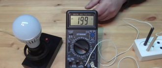
The tester consists of two parts - main and remote, each with 4 LEDs. The main part is connected on one side of the cable being tested, the receiver on the other.
When the device is connected to a cable line, the main part alternately sends a signal to each conductor, lighting up the corresponding LED. The remote part of the tester receives the signal, and the LED corresponding to the line with the signal lights up. If the cable cores are installed in the correct order, all LEDs on both parts of the device light up synchronously and alternately.
* The greater the bandwidth (frequency band), the more data can be transmitted in a certain period of time
without loss of data transmission quality (since data is transmitted simultaneously).
Source: EnergoMIX magazine No. 3 (4)/2013
Source: www.netko.ru
Category and containment
The twisted pair category is very important. To connect to the Internet or conduct communications for a computer network, you should use a category of at least CAT5. In exceptional cases, CAT6 and CAT6a are suitable. Category designations are embossed on the shell. There are a total of 7 types of categories for twisted pair:
- I - 1 pair (bandwidth 0.1 MHz): used in telephone communications.
- II - 2 (1 MHz): networks with data transfer rates up to 4 Mbit/s.
- III - 4 (16 MHz): 10 and 100 Mbit/s.
- IV - 4 (20 MHz): up to 16 Mbit/s.
- V - 4 (100 MHz): 100 Mbit/s (2 pairs are used).
- Ve - 4 (125 MHz): 100 Mbit/s (2 pairs) and 1 Gbit/s (4 pairs).
- VI - 4 (250 MHz): from 1 to 10 Gbit/s.
- VII - 4 (600 MHz): shielded up to 10 Gbit/s.
You might be interested in this Standard requirements for crimping RJ-45 twisted pair cables
Twisted pair also differs in the shape and color of the sheath. The common type of power cord is gray sheath. The orange (bright red) color of the sheath indicates that the power cord does not support combustion. The latter type of wire makes sense to use in areas prone to fire. In addition, twisted pairs are flat and round. They do not differ in technical characteristics.
The Ethernet cable consists of 2 (4 wires) or 4 (wires) pairs. At speeds up to 100 Mbit/s, 2 pairs can be used. If the data transfer rate is in the range from 100 Mbps to 1 Gbps (1000 Mbps), then all 8 wires (pairs) should be used. When designing your home network or connecting to the Internet, you should take these features into account. It is better to stretch 4 pairs at once, since if the information transmission speed increases above 100 Mbit/s, you will have to re-tighten the cable.
Types of LAN cables
Nowadays, all companies are trying to rid their gadgets of wires by switching them to Wi-Fi or Bluetooth. Therefore, over the past three years, many new products have been released that have wireless connection and data transfer functions. But, unfortunately, these features cannot fully function on personal computers or laptops, so they use so-called LAN wires.
You can purchase such a product for every taste and color at https://www.tk-neva.ru/catalog/category/lan-kabel/. To choose the cables you need, you need to know what types they come in; for this, it is recommended to read this article to the end.
Types of lan cables
LAN is a network cable with which you can connect several computers into one network or connect them to the Internet. There are three main types of products:
- coaxial cables;
- twisted pairs;
- fiber optic products.
The coaxial type is the very first representative of lan cables. Today it is used very rarely, but at the same time it cannot be abandoned forever, since it remains indispensable for some tasks.
It consists of a metal conductor wrapped in an insulating layer. This entire structure is securely packaged in copper or aluminum braiding. So that such wires can be connected, a bnc adapter is used.
The disadvantage of such a cable is its dependence on electromagnetic fields, because of this they are not used in creating computer networks, but only in setting up and connecting satellite dishes.
Twisted pair has rapidly replaced coaxial products. This cable is called so due to its structure. It contains paired conductors consisting of copper.
Fiber optic product is the most common type of cable for connecting a large number of computers into one large local network. And all this because it has very fast data transmission and a shell protected from interference and various influences.
This type of cable can transmit data and signals over 100 kilometers. The cost of such products is low, but to purchase adapters and other equipment you need to spend a little money, as the cost increases significantly. Therefore, such a cable is most often used when building huge networks, where data transmission will be carried out over a long distance, and the speed of the Internet connection must be very high.
See also:
TD Skala: cable products at manufacturer prices https://euroelectrica.ru/td-skala-kabelnaya-produktsiya-po-tsenam-zavodov-proizvoditeley/.
Interesting on the topic: VVGng - what is it?
Tips in the article “Types of SIP wire” here.
To correctly install a fiber optic cable, you need to have certain knowledge and quite expensive equipment.
What is twisted pair crimping and how to do it
Twisted pair pinout
The connection of cable cores with a connector is called crimping - the contact group of the connector, after distributing the wire cores in it, is pressed inward, piercing their insulation and fixing the cable. This creates a reliable and high-quality connection. The most popular connectors are the rj45 model.
The rj45 socket through which the pinout is performed is often referred to by experts as the 8P8C connector. This marking indicates that both the plug and the socket itself have 8 contacts. All these contacts can be connected in different schematic variations according to the type of cable connection.
Pinout of the rj-45 socket: the marking for the T568A standard is circled in red, T568B is circled in blue
Rg 45 pinout of 8 wires comes in two standards: T568A and T568B. The latter is more popular and is used much more often, as it is designed to connect a PC to a router or modem. The first standard was created to connect two PCs to each other.
Before considering the crimping process, it is logical to indicate variations in connector connection diagrams. There are only two of them: straight and cross.
All twisted pair wires are marked with a specific color, which allows for quick pinout and further crimping of the rj45 socket. The veins of a single pair are similar in color, for example, blue and blue-white.
The differences between straight and cross crimp configurations are obvious. Direct variation is a circuit solution when the colors of the cores on two opposite edges of the cable coincide.
Cross variation involves a scheme where, on opposite edges of the cable, the color matching of the cores is slightly changed. Most often, conductors numbered 1, 2, 3 and 6 are swapped.
Each of these schemes provides for the placement of conductors on opposite edges in such a way that conductor No. 1 is located opposite conductor No. 8 and vice versa - conductor No. 8 is located opposite conductor No. 1.
In addition to the above 2 configurations, there is also an intermediate one - console. It involves placing conductors on the edges of the cable in an inverted order. Core No. 1 from the first connector corresponds to core No. 1 from the second connector. Conductors No. 8 also correspond to each other.
How to properly crimp an 8-core internet cable
To prepare a twisted pair for operation, you need:
- the LAN cable itself, the length is determined according to needs, but not more than 55 m for categories 5...5e;
- side cutters (aka wire cutters) or a sharp knife for trimming insulation and cutting cables;
- RJ45 connectors and caps (the latter is not necessary, but significantly improves the quality of crimping the Internet cable);
- special pliers for crimping, they are called crimpers. By the way, on a professional tool there is an analogue of side cutters for stripping the ends of the wire;
- LAN tester.
Procedure
- After measuring the required length of the wire, insulation is removed from the edges to a length of 10...20 mm. This can be done with a knife - carefully walk around the circle, cutting the insulation, and then pull off the cut protection with tweezers. If there is a special cutting thread in the twisted pair (it is usually white), you can pull it, cutting the protection along the cable to the desired length. After this, the turned-off fragment of insulation is cut off. If the crimper (crimping pliers) has a special blade, it is better to strip the cable with it. This is what the wire should look like after cutting off excess insulation and carefully trimming the ends of the pairs (this must be done to make it easier to insert the wires into the connector contacts).
- Next, you need to determine the crimping pattern. It can be straight (both ends of the wire are connected to the connectors in the same way) or crossover (crossover, the two ends have different positions of the pairs in the connector). The direct type is used if you need to connect a device to a switch - for example, a laptop or computer, printer, TV with a router or hub. A crossover is used to connect two devices - for example, a laptop with a desktop computer.
Crimping an 8-core internet cable – diagram - Separate the wiring pairs, align them and trim the ends if necessary - all wires must have the same length and be strictly parallel.
- Insert the prepared wires into the connector contacts and crimp them using a crimper.
This is what the cable looks like (schematically) after crimping.
Surely the user has a question - why were caps on the list of necessary items and at what stage should they be used? They are put on a wire that has already been cut, but with the insulation not yet removed, and slide onto the already crimped connector.
The presence of such a cap prevents the wire from bending in the place where the insulation has already been removed and there is no connector yet. Thanks to this, there is less risk of breaking thin wires in a given place, and the period of use of the twisted pair is longer.
Interestingly, the cap also protects the connector latch (the bar that is pressed to insert the connector into or remove it from the device) from being accidentally pressed.
How to crimp an 8-core RJ45 cable is discussed in more detail in the training video.
Types of color schemes for crimping LAN cables
In accordance with the EIA/TIA-568 specification, there are 3 main color schemes for crimping twisted pair LAN cables (patch cords) using the rj45 connector model.
Patch cords (also known as patch wires) are intended to connect two devices, for example, a PC with a hub, another PC, or a switch. Making patch cord is easy. You need to take a cable of the required length, where the cores are made of stranded wires (to avoid fractures due to frequent bends), and crimp its edges with connectors of the rj45 model.
Which patch cord to choose
Since this article is about connecting a computer to a router, the easiest solution would be to use the patch cord that comes with your router for this purpose. Routers from all manufacturers are equipped with such a cable. But there is one caveat - it is usually very short, most often about half a meter . Rarely is it longer. Therefore, it will suit you if the computer and router are nearby.
But often the router in an apartment is located in the hallway or in the kitchen, and the computer is in one of the rooms. Therefore, a patch cord several meters long may be required. It can be purchased at the store. This is the most convenient option. You can, of course, buy a piece of twisted pair cable and RJ-45 connectors of the required length and make the patch cord yourself. But the price of the components will not be much lower than the cost of the finished cable. And for crimping you will need a special tool, which does not make sense to purchase for one-time use. If you still decide to crimp the twisted pair cable yourself, you can learn how to do it correctly from a separate article on our website.
Selecting a wire pinout diagram
The specific pinout of rg45 8 wire is determined by the variation in the connection of computer devices. Direct is mainly used to connect a network card to a switch (hub).
Cross order is used when there is a need to connect two network cards on different PCs. This configuration was used to switch older hubs.
At the current stage of development of digital technologies, the crossover scheme has actually become unclaimed. The reason is the development and gradual implementation of automatic detection of network type terminals.
Technical differences of network cables
Packing a home electrician's bag
The main differences between network wires are:
- Range of stable data transmission;
- Noise immunity;
- Bandwidth;
- Signal attenuation.
Differences in physical network cabling
The main differences between physical network cables include the following:
- Transmission core thickness;
- The material of the external insulation of the conductor itself and its internal cores;
- Tensile strength;
- Flexibility.
Also, all network conductors differ in the types of connectors used to connect them to various devices.
Twisted pair crimping procedure
Crimping of a twisted pair of 8 wires can be performed according to two standards: 568A and 568B. They come in two types - direct or cross-connection. In addition, there is a simplified pinout type, crimping 4 conductors, not 8. However, this variation does not support high traffic speeds - no more than 100 Mbit/s. Each option requires its own crimping scheme.
Straight 8-conductor cable
Straight twisted pair crimp
Direct crimping of all 8 conductors is necessary to ensure high-speed Internet access. This crimping will allow data transfer at speeds of up to 1000 Mbit per second.
Color structure of twisted pairs:
- orange and white,
- orange,
- green with white,
- blue,
- blue and white,
- green,
- brown with white,
- brown.
This crimping method is most relevant when connecting a router to a PC. The cross variation involves a slightly different distribution of conductors.
8-wire crossover
Direct cross crimp
This type of crimping is used infrequently, as it is intended for connecting two switching devices or two PCs to each other.
The order of conductors by color is as follows:
- green with white
- green
- orange and white
- blue
- blue and white
- orange
- brown with white
- brown.
The crossover is slowly becoming a thing of the past, because modern devices are equipped with MDIX technology and automatically change the signal supply. Nevertheless, for old equipment such crimping will still serve.
Straight 4-conductor cable
Crimping a 4-core cable
This crimping option is used to connect a PC to switching-type devices, for example, modems.
Crimping rj45 wires, color scheme:
- orange and white,
- orange,
- green with white,
- green.
This configuration is simpler and involves data transfer at low speeds - up to 100 Mbit per second. If the cable breaks, you can simply transfer it to the 4 free contacts on the connector.
4-wire crossover
Crimping in this way uses four cable cores, that is, 2 pairs. In this case, conductors of any color can be used for twisting. Traditionally, green and orange conductors are connected.
A crossover of this type is used extremely rarely, exclusively in home networks, for example, to connect an old PC to another outdated computer. The choice of conductor color does not affect the speed of information transfer.
Crimping a 4-pair cable to two computers
The advantage of an 8-core cable is the ability to split the cable for crimping into two network devices; this is very convenient, especially when laying an additional cable is difficult for various reasons.
Correct "pinout"
To combine two devices into one network, you will need a piece of cable (patch cord), on both sides of which RJ 45 connectors (Jacks) are attached. To build a working computer network, it is important to make the correct wiring or, as experts say, pinout. The use of RJ 45 connectors allows you to make a patch cord with a high-quality connection of wires, without resorting to the soldering process.
The standard RL45 connector has 8 contacts, each of which has its own wiring. The connection of wires with connectors is done based on existing standards: TIA-568A and TIA-568B. Most often, to create a 100 Mbit network, the user uses an 8-core cable, although 4 cores are quite sufficient. Below we will consider crimping a twisted pair of 8 cores.
To connect a computer with a switch (router), a direct twisted pair crimping circuit is used, i.e. patch cords are used, with the same pinout on both ends. To connect two computers to a network, pairs of wires must be crossed, so in one patch cord they make: one end according to standard A, the other must correspond to standard B.
Crimping procedure
Now let's move on to the correct way to crimp the cable. Be careful when working - the main thing is not to damage yourself, and the connectors are cheap)
Step 1. Remove the insulation
First, remove the insulation from the wire - you can carefully pry it off with scissors or use a stripper on a crimper - insert it, turn it, and the wrapper comes off. It is fragile and can be removed quite easily. You don't need to remove much insulation - a couple of centimeters from the end is enough. If anything happens, you can trim everything later. The pliers have special marks indicating at what level the coating should be cut.
Step 2. Straighten the wires
Now we take our wires, straighten them and arrange them according to the pinout diagram. From the recommendations - try straightening them with a pencil or hand - they become smooth and closely spaced to each other - which is what we need.
Step 3. Trim
Now is the time to cut and straighten our wires. We cut it either with wire cutters, or with the same pliers, or even with a knife. Leave about a centimeter of clean wire. With practice, you will learn to accurately check the distance.
Step 4. Getting into the connector
The hardest part. Now we need to insert our design into the connector. When inserted, the connector is positioned with the leg down. Why is it difficult - the wires try not to fall into their grooves, they crawl into neighbors, bend, and get tangled. Here the recommendation - patience and once again paying attention to the pencil treatment - helps.
Step 5. Insert all the way
After the hit, we press on the cable so that the wires go all the way. In this case, the wrapper will be hidden in the connector itself. If the wrapper does not fit into the connector, fractures are possible in the future. If the opposite turns out to be short, the wires will not reach the knives. So everything is done with experience and by eye.
Step 6. Crimping
Now is the time to tighten our knives - the methods were discussed above, but it is better to use pliers. Take it and live it.
Step 7. Check and refinement
Be sure to check the connection on your computer or router before putting away your tools. Sometimes it may not work out the first time. The easiest way to correct the situation before getting upset is to squeeze the knives again, but harder. It helps a lot.
If there is no connection, pay attention to this:
- Are the wires routed exactly according to the diagram? Didn't they fly out? Look through the connector.
- Have the wires reached the stop of the connector? Were the knives able to reach them?
The rest can only be attributed to cable failure.
Initially, before crimping the network cable, you can install these casings. They perfectly protect against bending near the connector, but in practice everything works without them. There are a lot of species, that’s not what the article is about. For reference.
Network cable specifications
Twisted pair is equipped with 4 or 8 cores. However, their number can increase to 1000. As a rule, the wire consists of a set of copper conductors with an insulating coating, the diameter of which is in the range of 0.4-0.65 mm. To make the insulating coating of conductors, manufacturers use polyvinyl chloride (the presence of chalk in the product makes it easier to trim the outer sheath during installation).
Basic indicators of Internet wire
The coating is made in different colors, due to which they are separated when finished. But often it is painted gray, with length markings and information about the manufacturer. The thickness of the outer shell is from 0.5 to 0.6 mm.
Crimping without crimper and other alternatives
If you don’t want to spend money on a tool for one-time crimping, which is quite logical, you can use a small flat-head screwdriver for your purposes.
The task is to press the terminals inward
We proceed according to the scheme described above until we reach the point of crimping the cable. Place it on a hard, flat surface with the contacts facing up. We take a screwdriver and press it on the contacts one by one. Be sure to wear a glove on the hand that holds the cable, otherwise it can be damaged by a tool that comes off. In the process, you will understand how the knife protrusions penetrate under the insulation and your work will go faster. We press hard, otherwise reliable contact will not work. Make sure that the contact is recessed slightly below the edges of the connector body. Place a rag under the cable to avoid accidentally damaging the table surface.
Fixing the connector on the insulation
After you have crimped all the contacts, carefully insert a screwdriver into the clamp to securely secure the connector to the cable. We do the same with the other end of the cable. After work, you will notice that the contacts are slightly damaged by the screwdriver; the crimper does not give such an effect.
Now take the cable, install it into the network and check its functionality. If the result is negative, then do not rush to blame your work, perhaps the problem is something else, check all the components of the network:
- If you have a cable that is known to work, replace the one you just made with it and see if a signal appears. If there is no such cable, then try connecting another device - this way you can find out if the problem is in the computer.
- Double-check the sequence of wires in the connectors; perhaps you didn’t notice something or simply got it mixed up.
- If such an oversight is discovered, the situation can only be corrected by biting off the end of the wire and installing a new connector.
- Try to press the contacts - perhaps they did not fit into the vein well.
- Also check your router and network settings on your computer - this is also a very common problem.
Such connectors do not need to be pressed.
Today you can find crimpless connectors in stores - they are more expensive than usual, but they are popular for their convenience. An example of such a detail is shown in the photo above. It has an opening casing, under which the slots for the wires will be visible. At the end you will see a hint on how to place the conductors to get an oblique or straight connection. Then the casing closes tightly. Please note that it has hard ribs on the inside. They will press the wires deep into the slots where the sharp contacts are located. In general, the principle is exactly the same, but it’s not the blade contacts that are pressed in, but the wires. The result is a high-quality connection without damage, and you don’t need any tools other than a knife and wire cutters for this.
This concludes the review of the topic. We think that if you follow the instructions exactly, there should be no problems with the connection.
Carrying out large-scale renovations almost always includes installing a home electrical network. Consequently, the question arises - which cable to use for wiring in an apartment or house? It would seem, what is the difficulty? The wealth of choice often only confuses the inexperienced consumer. In addition, not all of the samples on sale are suitable for the intended purpose. Therefore, in a special publication we will try to answer what type of cable and why you should choose.
Crimping diagrams and twisted pair markings
When crimping a twisted pair of 8 cores, be sure to take into account the markings of the conductors. Each connection necessarily corresponds to a specific color scheme, which requires strict adherence. Otherwise, the signal will not pass through, and the network will not function.
Lazy crimp 2 pairs
In the considered option, direct crimping of the cord is used, where not 8, but only 4 cores are involved. Therefore, this method got its name for those who do not want to bother with all the veins. However, such a connection is only suitable for low-speed networks.
This type of crimping is not recommended for use at this time. The fact is that Internet speed is constantly growing, equipment is improving, and the 4-wire circuit stops working under new conditions. Therefore, sooner or later, you will have to switch to the standard scheme. If the network was initially laid with an 8-core cable, then all that remains is to crimp the RJ connectors in a new way, and everything will work. But, if the network is equipped with a four-core cord, then it will have to be completely changed and re-laid.
Pinout for a local network with more than 2 computers
When using RJ 45 connectors, pinout for connecting more than two computers to a network is carried out according to the standard scheme. All veins are untwisted and laid from top to bottom or from left to right as shown in the figure.
The conductors are aligned, cut, and then they can be crimped. After this, each twisted pair connector is connected to its own socket.
Direct pinout is marked as 568B
Direct connection is necessary in order to connect a HUB, router or switch to a computer. This method is most widespread in Russia. It is marked as 568V, and the wiring is carried out according to the usual scheme, starting with a white-orange conductor and ending with a brown one. There is a direct crimp here, since the wires are located the same on both connectors.
Crossover pinout is marked as 568A
Another way to crimp a twisted pair cable. To connect devices of the same type, for example, two computers, a crossover circuit or crossover labeled 568A is used. In this case, the first plug is connected in the usual way, and the second is connected by replacing the orange and white-orange wires with green and white-green wires. The conductors end up upside down, which is why the circuit got its name.
Direct crimp with 4 core twisted pair double pair wire
A cable with four cores is used when installing internal networks with low speeds. With large volumes, you can save significant money, since such a cable is much cheaper than a conventional twisted pair cable with 8 cores. Crimping is performed in the sequence shown in the figure.
However, the use of such networks has a number of limitations, primarily in terms of speed. In addition, it is not possible to supply power to the device when needed.
RJ 45 twisted pair compression circuit with POE standard IEEE 802 3AF
This circuit, made using PoE technology, allows not only to transmit information signals, but also to supply power to the router, switch, adapter and other devices. For example, when connecting video cameras, a separate power cable is not required. Thus, the connector combines two functions at once - data transmission and power supply to the device. The voltage in this pinout is supplied through blue and brown conductors.
It is strictly forbidden to use twisted pair to supply 220 volts, as this can lead to unpredictable consequences. The fact is that the cross-section of the cable in the network is only 0.51 mm2 and is designed for a current of up to 1.5 A. If the current needs to be increased, two conductors are connected in parallel and then the figure increases to 3A.
Cross-circuit for pumping speed of 1 Gbit/s
The connection scheme is used in high-speed networks, up to 1 Gbit/s. Eight wires are crimped in the sequence shown in the figure.
Rollover Cable console cable crimping diagram
Each end in such a connection is crimped mirrored in relation to each other. This scheme is used to configure a switch or router using a computer.
“Lazy crimp” 2 pairs
Oddly enough, this twisted pair pinout is used very often, since it is quite simple. If you have already tried to crimp all 8 wires at least once, then you have most likely encountered some problems when the wires are bent, do not fall into the desired groove, and as a result you have to start all over again. This scheme is used only when connecting devices and network equipment that do not need to use speeds above 100 Mbit per second.
Let me remind you that when crimping 4 pairs, a network cable can transmit data at a speed of 1000 Mbit per second. If you use only 2 pairs, then the speed drops to 100. Of course, in most cases this speed is enough, but I strongly do not recommend using it.
4 wire crimp standard
The fact is that the speed and flow of information exchange in organizations is beginning to increase. Consequently, at some point this pinout will not be enough. Then the boss will force you to go and re-crimp all the cables to the usual standard circuit. You will end up doing double or even extra work. That is why, if you have a standard 8-core cable, then we use a twisted pair connection according to the diagram from the last chapter.
The same goes for home. Imagine that you exchanged your old 100 Mbps router for a new one that supports 1 Gbps. If you previously had a different pinout for 2 pairs, then you will need to re-crimp everything. In the worst case, you will need to change the 4-core cable to an 8-core one.
NOTE! The RJ-45 connector differs between 100 Mbit/s and 1000 Mbit/s in the same way. The first has 4 cores, and the second has all 8.
Types of network cables for the Internet
The list of main types of network cables:
- coaxial;
- fiber optic;
- twisted pair
The design of a coaxial wire includes a conductor with a dense insulating coating, a copper or aluminum braid, and an outer insulating layer. In addition to connecting to the network, Internet products are used to translate signals from antennas and television satellites to build high-speed digital networks (cable TV).
RJ 45 pinout – Twisted pair crimping: diagrams, connection methods
The configuration of the wire connectors is different:
- The BNC connector is attached to the ends of the cable, providing connection to the T-connector and barrel connector.
- BNC barrel connector is designed for connecting damaged elements or extending the wire to expand the range of the network or connect additional electrical equipment.
- A BNC T-connector is a tee used to connect computer equipment to the main network line. The wire has 3 connectors (1 is intended for output to a centralized network, 2 connectors are necessary for connecting a local system).
- The BNC terminator is designed to act as a ground plug, preventing the signal from propagating outside the local line. The connector is required for stable operation of network connections that occupy a large area.
To create local lines, a twisted pair network cable is used. The products include pairs of twisted copper conductors with an insulating layer. A standard wire consists of 4 (8 conductors) or 2 pairs (4 cores). According to standards, there should be no more than 100 m between devices connected by cable. The wire is available standard or with protection. To work with the cable, an 8P8C connector is used.
Before choosing a twisted pair Internet cable, you need to determine the subtype based on the characteristics of the outer layer (thickness, presence of reinforcement, composition). The UTP wire with a plastic outer layer is not protected and is produced without grounding. F/UTP, STP, S/FTP products are manufactured with shielding.
Twisted pair cable markings reflect categories based on the color of the insulating layer:
- gray (used in the interior spaces of buildings);
- black (used to designate products coated to protect against precipitation and electromagnetic radiation, used for outdoor structures);
- the orange hue is used to indicate non-flammable polymer compounds.
Fiber optic cable is an improved wire for building network lines. The product consists of plastic fiberglass light guides with plastic protection. Cable products are characterized by high speed of information transfer and are resistant to line interference. The wire can connect systems over long distances. Products are divided into single-mode and multimode.
Fiber optics use different types of connectors (FJ, ST, MU, SC). The wires are inexpensive, look aesthetically pleasing, but require the purchase of additional equipment and are difficult to install. The products are used to form large-scale network systems and create access to the Internet at high speed.
Copper conductors in an Ethernet cable are produced:
- whole;
- twisted.
Solid conductors are strong, reliable, durable, but less flexible. The products are intended for stationary indoor systems or short installations on external structures. Stranded products consist of thin copper wires twisted together. The cables are durable, flexible, and are designed for placement in work spaces and in places where objects need to be moved.
It will be interesting➡ Twilight switches
How to crimp an RJ-45 cable correctly?
There are various ways to crimp an RJ-45 cable, including even crimping a connector without special pliers, using an ordinary flat-head screwdriver.
But we will look at how to competently make a reliable and functional working patch cord, the characteristics of which are no different from purchased models.
Selection and preparation of tools
Having a set of special tools on hand makes crimping a patch cable much easier. Of course, you will have to allocate money to purchase a crimper, stripper, tester or crosser, but if you buy a quality tool, it will last for years.
To properly secure the connectors to the cable you will need:
Twisted pair crimping pliers - crimper
Insulation removal pliers - stripper
Cable diagnostic tester
Crossing tool for termination
The main tools listed are pliers and a tester - this is the minimum set required for correct pinout and crimping of twisted pair cables.
When buying pliers, you need to check their quality and it is advisable to test the tool first. Some crimpers are equipped with blades that can be used to strip the veins.
Step-by-step instructions for crimping
To make a patch cord, you will need to prepare materials - cable and connectors, arm yourself with a tool and choose a pinout diagram depending on what devices the finished cord will connect.
List of materials:
- a piece of twisted pair is no longer than 100 m - according to the Ethernet pinout, this is the maximum length of standards for household use;
- for one cable - two RJ-45 connectors (their marking is 8Р8С);
- set of tools – crimper, stripper, tester.
Most often, a cable is required to connect a PC to a network device, so we remember the direct crimping diagram, and for reliability, we simply put it in a visible place so that it is in front of our eyes at the time of distribution of the wires.
A ready-made color diagram can be found on the Internet and printed on a piece of paper - visual perception promotes memorization, and it will no longer be needed in the future
Do not forget that types A and B differ only in the location of the orange and green twists; both options can be used.
Step-by-step instruction:
- Step 1 – Cut a piece of cable according to the meter, without stock, but of sufficient length with wire cutters or crimper blades.
- Step 2 – We step back 2-4 cm from the end, make a circular cut on the outer insulation with a stripper, and then carefully remove it.
- Step 3 – The conductors are twisted in pairs, so before crimping, we unwind all the pairs, straighten the cores and distribute them according to the chosen pattern. In addition to the conductors, a nylon thread is hidden under the shell - you just need to pull it back.
- Step 4 – Trim the conductors. To do this, we retreat 1.0-1.3 cm from the edge of the outer insulation and cut off the wires with wire cutters strictly perpendicular to the axis of the twisted pair. We make sure that the multi-colored tips are the same length.
- Step 5 – Insert the conductors into the connector and push them all the way.
- Step 6 – We crimp: insert the connector with conductors into the desired connector of the crimper (marked 8P) and squeeze the handles of the pliers. You can hear a click.
- Step 7 - Check the reliability of the fastening - lightly pull the cable, as if trying to get the conductors out of the connector. When crimped correctly, the wires sit firmly.
- Step 8 – Test the finished patch cord for serviceability. We insert the connectors into the sockets of the tester, turn on the device and monitor the indication. If everything is in order, the lights will light up green in pairs. If there is no indication or the red light comes on, the procedure will need to be repeated.
The hand gets filled quickly - after several independent crimps. The crimping skill will come in handy when moving to a new apartment, where network wires are hidden in baseboards or sewn into walls and connected to computer sockets.
There is no need to worry that the cable is too long or short - you can always crimp the patch cord to the desired length. If the power cable is suddenly chewed by a dog or it is simply bent, you can quickly make repairs.
You may also be interested in seeing how you can connect twisted pair cables to each other, for this follow this link.
Lesson 13. Network LAN cables
Let's look at what cables and connectors are used in the LAN.
Twisted pair (UTP/STP)
Modern networks use cables called UTP and STP.
UTP - Unshielded Twisted Pair - unshielded twisted pair cable.
STP - Shielded Twisted Pair - shielded twisted pair cable. STP is used for greater noise immunity from external electromagnetic influences, such as from electrical wiring. But it costs a little more and is a little thicker.
So let's look at its device. It consists of 4 twisted pairs. Remember the colors and order of connection to the connector. The connector is called RJ-45.
Now remember what cable pinout will be at each end and what this connection is called:
In the first case, the pinout is the same - such a connection is called straight-through.
In the second case, the green and orange pairs swapped places - this connection is called crossover.
What are the 2 connection types used for?
A straight cable is used to connect devices of different names. For example, computer and switch, router and hub, hub and server.
A crossover cable is used to connect devices of the same name. For example, switch and switch, router and router, computer and router, switch and hub, computer and computer.
Console cable (Rollover)
Rollover is a console serial cable that is used to configure equipment through the terminal, that is, on the command line.
He looks like this
One end has an 8-pin connector that looks like an RJ-45. This end is connected to the console port of the equipment. The second end has a standard DB-9 connector that connects to the computer.
Many modern laptops no longer have serial ports, so you often have to use special USB adapters
Optical cables
In addition to UTP/STP copper cables, LAN networks also use optical cables. Instead of an electrical signal, laser beams propagate through such cables. Most often, such cables are used for the 1000Base-X (Gigabit Ethernet) standard, as they support data transmission over distances greater than 100 m.
Optical cables and connectors look like this
The cables themselves connect directly to removable SFP (Small Form-Factor Pluggable) modules, which consist of a receiver and a transmitter (laser)
Comments for the site
Cackl e
Development of Joomla extensions
Examination
After crimping the twisted pair according to the desired pattern, you need to check the connection. To do this, it is best to use a special LAN tester device. We simply turn on the device and connect one part of the device to one end of the cable, and the second part to the second end. If all the wires are illuminated in the correct order, then you have crimped everything correctly. If any of the wiring does not light up or flashes incorrectly, you will have to re-crimp the cable.
Sources
- https://homius.ru/raspinovka-rj-45.html
- https://StrojDvor.ru/elektrosnabzhenie/raspinovka-vitoj-pary-na-4-ili-8-provodov-kak-pravilno-obzhat/
- https://bezopasnik.info/rj-45-%D1%80%D0%B0%D1%81%D0%BF%D0%B8%D0%BD%D0%BE%D0%B2%D0%BA%D0 %B0-%D0%BF%D0%BE-%D1%86%D0%B2%D0%B5%D1%82%D0%B0%D0%BC-%D1%81%D1%85%D0%B5% D0%BC%D0%B0-%D0%BE%D0%B1%D0%B6%D0%B0%D1%82%D0%B8%D1%8F/
- https://safetyarea.ru/articles/obzhim-vitoy-pary-rj45-skhema/
- https://prohelps.ru/pinout-rj45/
- https://rusenergetics.ru/raboty/obzhim-vitoj-pary-konnektorom-rj-45
- https://WiFiGid.ru/poleznoe-i-interesnoe/obzhim-vitoj-pary
- https://stroyday.ru/remont-kvartiry/elektropribory-i-osveshhenie/kak-obzhat-kabel-rj-45-svoimi-rukami.html
- https://WiFiGid.ru/poleznoe-i-interesnoe/raspinovka-rj45
- https://sovet-ingenera.com/elektrika/wires/raspinovka-rj45.html
How to connect to the Internet using a network cable
To get 100-megabit speed, you should use 2 pairs out of 4 - green and orange. The remaining two are used to connect another computer. It is also possible to divide the conductor into 2 parts. This way you can get a double cable. But it should be taken into account that the parameters of such a product will be identical to those of a single one. Using such an element may significantly degrade the quality and speed of data transfer.
Important! If you perform crimping without complying with the requirements of the standards when connecting to the network, an error may occur. This will result in loss of transmitted data or inoperability of the conductor (this indicator may directly depend on the length of the cable).
To determine the correctness and efficiency of crimping the product, you must use a special cable tester. This device consists of a transmitter and receiver, which are included in the kit. Using the first device, a signal is supplied to each of the wires of the conductor, and the transmission is also duplicated by indication due to the presence of LEDs on the receiver itself. If all 8 indicators light up, then this indicates that the conductor has been crimped correctly.
How is the connection made using a wire?
There are several options for choosing a cross-connection pattern. However, they are limited to Power over Ethernet according to the IEEE 802.3af-2003 standard. This option operates automatically if the cores in the cable are connected one to one.
That's all. The main thing when installing any wire is to avoid bends exceeding eight outer diameters. Strong bending can cause increased interference or lead to destruction of the cable itself.
Installing a network card into the system unit.
To install a network card on the motherboard, you first need to remove the side cover to access the inside of the case. Then, after you have removed the side cover, you will see a motherboard with peripherals installed in it, but to install a network card, pay attention to the photo, you will need a PCI connection interface, this slot is present on every motherboard, unless of course you have equipment is already installed there, for example an old network card that you want to replace.
First, we need to prepare a place if the network card is installed first, first we will make sure that the slot for the card is free, then we need to remove the plugs from the back of the case; in sophisticated cases they are unscrewed, and in simpler cases they are broken out. Next, we install our network card in the free slot. Please note that in this photo we have 4 places where you can install a network card; we specifically took a couple of pictures of different motherboards to understand that there can be more than two slots for installation.
Next, after the process is completed, you need to install the driver from the disk when you start Windows for the first time; they usually come with the network card. If you do not find this disk in the kit, install it manually through the task manager by automatically searching and installing the driver for the network card.
Checking the adapter
If you configured the Netgear WNR612V2 router or any other router, you must have seen a network card port (RJ-45) on the back of the system unit. It looks like this:
If the connector is located near other ports (usually USB), you are dealing with an integrated network card. If the RJ-45 port is located separately from other connectors, then your system unit has a separate board installed that is responsible for connecting to the network.
After detecting the port, you need to check whether the hardware is installed correctly in the system.
To do this, go to Device Manager and make sure that the network card is detected and its drivers are installed correctly.
Reinstall them if necessary.
The network adapter can also be disabled in the BIOS. Restart your computer and go to Basic I/O.
Find the “PCI Confuguration” parameter (usually it is located in the “Advanced” section). Make sure that the “LAN Controller” item is set to “Enabled”.
Where is the discrete network card connected?
Almost any motherboard is equipped with an integrated Ethernet adapter, which is used to connect a computer or laptop to the network. Like any electronics, this chip can fail. Changing an expensive motherboard because of such a small thing, if it still works well, is a little expensive.
And you don’t want to be left without the Internet - you won’t be able to see funny pictures. Don't play tanks. In such cases, it is worth installing a discrete Ethernet card, which is connected as an additional module.
You can use a network card that connects via a USB port. The disadvantage is that one such slot will always be occupied, and there may not always be enough of them to connect all peripheral devices.
There are also advantages: connecting everything is very simple. It is enough to install such a module in a free port and wait until the drivers are installed automatically.
More popular are LAN controllers that need to be installed in the PCI slot on the motherboard. This part looks like a small scarf with a port for connecting a cable at one end. It is quite inexpensive, even if it supports gigabit data transfer speeds.
The PCI slot can operate at frequencies of 33 and 66 MHz, depending on what device is connected to it. The slot speed is quite enough for comfortable Internet use with data transfer speeds of up to 150 Mbit/s.
As a rule, providers rarely provide higher speeds, since such tariffs are not popular.
How to install an Ethernet controller
To change the board or insert a new one, you need to open the left cover of the system unit by unscrewing a couple of screws from the back. Having selected the PCI port where you are going to add a new part, break off the blocking plug on the back cover opposite so that there is somewhere to remove the part panel for connecting the wire.
First try on the network card to the slot to determine which plug is unnecessary. After removing the plug, carefully insert the LAN controller into the port and secure the bracket that rests on the back cover of the system unit with a screw.
You can put the cover of the system unit back, connect the cable to the LAN port and install the drivers. It is possible that Windows will find suitable software in its own database and install it independently.
If this does not happen, the driver needs to be installed from the disk that comes with the kit or by first downloading it from the manufacturer’s official website, which is more common; now there are few users who install CDs or DVD-roms on their PCs.
If you replace one LAN card with another, you don’t even need to break out the plug in the case: you dismantle the old part and install the new one.
The articles “Procedure for assembling a computer” and “Parts and components necessary for assembling a computer” will also be useful for you. I would be grateful to everyone who shares this post on social networks.
Connecting the card in BIOS
What signs can be used to determine that the card was recognized by computer hardware?
If the network card is not working, then first of all you need to determine whether it is recognized by the computer hardware. Currently, all boards support Plug-n-Play technology, which means that when they are inserted into a computer, they are automatically assigned the necessary hardware parameters (interrupts, I/O ports, memory addressing). After this, these parameters are picked up by the network card driver, which is either in the kernel (in UNIX-like OSs) or installed as a separate module (in Windows). Sometimes, if a card is not functional or is completely incompatible with a given version of the operating system, you will not see it at all in the operating system output. If the card is somehow detected by the operating system, then information about it will appear in the boot logs (in UNIX this is the dmesg command). But before understanding the boot logs, you need to check whether the card is recognized in the computer’s BIOS.
to enable network card support in BIOS
To enable a card disabled in the BIOS or at least check whether the network card is recognized by the computer, you must:
- Reboot your computer.
- After the first successful squeak, quickly and alternately press and release the F2 and DEL keys on the keyboard. The fact is that one of these keys is responsible for launching the BIOS/UEFI setup screen on the computer, but which one is described in the documentation for the motherboard, but not for the computer.
- Therefore, by quickly and alternately pressing these keys, you are guaranteed to enter the BIOS on a running computer before loading the operating system.
- After the BIOS screen appears, you need to enter the item, which may be called “Integrated Phieriferals”, “PCI Devices”, “I/O Devices”, etc. It is usually second in order from the main screen.
- If you are interested in the built-in card, find the item “Onboard Devices”, “Network Devices”, “Onboard Lan”, and look there for items containing the word “Ethernet”. For example, but not necessarily, “PCI Gigabit Ethernet” - for a built-in wired network card, “Wireless Ethernet Adapter” - for a wireless Wi-Fi card, if the word Bluetooth appears, then this indicates a built-in Bluetooth adapter.
- If you are interested in a network card that you installed in one of the free sockets (slots) of the PCI bus, look for the words “Ethernet” and “Bluetooth” in the Slot# items, where # is the number of the slot in which you installed the card;
- Next to the built-in map item, and sometimes for an external map, there may be Enabled, Disabled, Auto icons. The Enabled item means that the device is turned on, Disabled means it’s turned off, Auto means the behavior is determined by the BIOS/UEFI firmware.
- To make sure that the device is enabled in the BIOS, items 4 and/or 5 must be present, and in item 6, the devices should be Enabled or nothing. Correct these values.
- If you do not see the indicated items, then most likely you have hardware problems with the equipment or BIOS. Try replacing the hardware. If, under no circumstances, does the board come out of the Disabled position, then, apparently, it is incompatible with your computer. Try replacing the hardware as well. (Or stop using it).
- After making changes, press F10, select Yes as confirmation and restart your computer. Next, check whether the card is recognized by the operating system.
Connecting a card in Windows
How to check the card status in the Microsoft Windows operating system?
Any device recognized by a Microsoft Windows operating system version higher than Windows XP will appear in its Device Manager. You can get to the Device Manager from the “System” item in the Control Panel (called by pressing the Win+Pause key combination), but it’s easier to get to the Device Manager from the command line. To do this you need:
- Open the command line or Windows terminal with administrator rights (if you want to make changes);
- In the command line that opens, type devmgmnt.msc and press Enter.
How to connect an Internet cable to a power outlet
Having figured out which sockets and wires are suitable for Internet connections, you can move on to describing the process of their formation. The upcoming work, first of all, differs in the type of installation (open and hidden). In the first case, overhead-type products are used, and in the second, their built-in analogues are used. In addition, you will need to understand the type of cable connected to the outlets. For these purposes, a cable product is used, laid in special channels located in plastic skirting boards and not connected to power routes.
What is cable pinout and disconnection?
Before connecting an Internet outlet yourself, you will first need to understand the peculiarities of the procedure for crimping contact connectors. The main thing to pay attention to in this case is the order of the contacts on its connecting terminals ( pinout ).
Internet cable pinout diagram
Pinout (disconnection) refers to the sequence of crimping the lead wires on an Internet socket or RJ45 connector. The diagram according to which this operation is carried out is usually printed on a module with split contacts on both sides. In this case, color markings are used to indicate a specific contact connection.
The photo below shows a module from a Legrand socket with color markings for laying wires.
Modular connector for Legrand internet sockets indicating the color coding of the wires
Additional information: For sockets with an RJ45 connector, it is recommended to choose a 4-pair UTP cable from the “5E” series (photo on the right).
With its help, it is possible to provide a high-speed connection to the Internet (up to 1 Gbit per second at a distance of up to 100 meters).
Connecting the built-in socket for the Internet
With the hidden installation method, Internet sockets are recessed into a niche specially drilled into the thickness of the wall. A special socket box in the form of a plastic cup is pre-inserted there and attached to the alabaster. In this case, the supply wires are laid in grooves hidden under a layer of plaster, so that only the ends connected to the socket come out.
An Internet socket with an RJ45 connector can be connected to the Internet in two ways: according to standards “A” or “B” (user’s choice). The second option is most often used. In order to figure out where which wires are connected, you will need to carefully inspect the housing, remove the cover and study the markings. It must indicate the compliance of the contacts with the selected standard for the color of the conductor insulation.
The procedure for connecting an indoor Internet socket is as follows:
- First, a socket box is installed in the wall into which the socket will be installed.
- Next, a UTP cable is laid into the installed socket box, hidden in the wall. The free length of the cable for connection should be about 20 cm.
- After this, you need to remove the outer protective sheath of the twisted pair, being careful not to damage the insulation of the internal cores.
- The protective sheath of the cable is removed approximately 5 cm, after which the internal pairs of wires should be unwoven.
- The connection is made in accordance with the pinout according to the TIA 568 standard (A or B) according to color (the marking is indicated on the module with split contacts).
One side of the module should have the following colors:
- white- orange
- orange
- white- green
- green
On the other side:
- blue
- white- blue
- white- brown
- brown
Step-by-step instructions for connecting an Internet outlet
Detailed step-by-step instructions for connecting the socket are presented in the photo gallery.
Connecting an outdoor socket
Surface-mounted (external) sockets are connected in exactly the same way as in the case of hidden installation. In the same way, the insulation is removed from the wire outlet and the twisted pair is untwisted, the ends of which are stripped and prepared for switching at the contacts. The connection diagram for Internet outlets is selected depending on their type.
At the final stage of the work, all that remains is to install the Internet socket in place and securely fasten it to the wall.
Briefly, what is a driver?
A driver is a program (software) that is needed to connect the operating system (OS) with devices connected to the computer and “explain” to the OS how to use them correctly. Almost every device that accesses the OS has its own driver: external devices (peripherals) - mice, printers, monitors, keyboards, etc. , internal (components) - video card, network adapter, motherboard, processor.
Drivers for most devices are already integrated into the OS, but it may turn out that for complex and specific devices, which include a network adapter, you will need to install the latest driver.
Detailed instructions for crimping an RJ-45 connector.
First of all, you need to remove the outer sheath of the cable. By the way, almost all types of twisted pair cables contain an internal thread, which makes it easy to remove the cable from the outer sheath when connecting to RJ 45 connectors (for computer networks).
Now you need to straighten all the wires laid together and measure the distance along the plug, attaching the cable to it so that all the wires sit in their seats until they stop. The outer sheath of the cable must be placed under the retaining clip.
After making sure that the measurement was made correctly, we cut the cable to the required length.
Now you need to insert the cable into the end of the plug so that all the wires fit into their guide channels all the way. This must be done so that the outer insulation of the cable falls under the connector clamp bar. After this, clamp the connector fixing bar with a screwdriver, while making sure that the wires do not come out of the landing channels. For convenience, you can fix the cable with the hand in which you hold the screwdriver.
At this stage of crimping, the connector should look like the photo below. Please note that the contacts are not yet recessed into the cable cores.
All that remains is to recess the connector contacts into the cable cores. You need to be extremely careful and press with feeling with a screwdriver on the contacts so that they sit in their places, while cutting through the braid of the wires.
When you recess the connector contacts into the cable cores, make sure that they sit in the same place in one line. Upon completion of crimping, it is advisable to verify the quality of the work performed and check the connection using a conventional tester. To do this, you need to set the switch on the tester to the resistance measurement mode or to the sound signal position and test all the working cores of the LAN cable you crimped.
If there is no resistance or sound signal, press the connector contacts to their seat. Of course, doing this with a crimper is much more convenient and faster, but if you do everything correctly, the output will be no worse than a crimped twisted pair cable with a screwdriver.
It would be nice to use an insulating cap as it would protect the cable from bending and the connector from dust and moisture, but I didn’t have one at home. In addition, the cap gives the cable some finality and beauty.
In the photo below, I decided to post a comparison of a crimped twisted pair cable by specialists from a well-known provider in Ukraine, who crimped the connector with a crimper about a year ago at my home. Their work in the photo is circled in red, and the connector crimped with a screwdriver is circled in green.
PS It is important to remember that the quality of the connection of your network depends on the quality of the network cable crimping. A poorly crimped or secured connector may work intermittently, which in the future will lead to its complete failure. If you find a broken LAN cable on your home network, then how to connect it. By the way, I recommend expanding your horizons and reading a short publication about between continents. Bye!
If you find an error, please select a piece of text and press Ctrl+Enter
.
Surely many have encountered such a situation when the “plug” of the Internet cable became dirty during operation, broke (this especially often happens with a plastic latch) - in general, the contacts came off and the Internet did not work well. The solution is simple: you just have to re-crimp the network cable.
For this we need:
1. The Internet cable itself - it is also called a patch cord, or twisted pair.
2. Several RJ-45 connectors (you will need one, and the rest in reserve)
3. Crimping pliers - all this can be purchased at any radio market.
We start with the fact that before crimping the twisted pair, we need to bite off and save the old connector - it will serve as an example for us in the future. And, of course, carefully, without damaging the “twisted pairs,” clean the insulation from the end of the new cable. To do this, you can use a special double knife on purchased pliers or simply open and clean the insulation with a penknife. In front of you will be 4 twisted pairs of colored wires. It is necessary to disconnect them from each other and bite them evenly so that they are all the same length.
Next we need to decide what pattern we will use to crimp the cable. And there are two of them. The most reliable way is to look at how it was crimped before - on the bitten off connector. If you are crimping a twisted pair from scratch, you will have to think about it.
Straight type
- suitable specifically for the case of crimping an Internet network cable in order to connect a computer to the Internet or router. It is called straight because both ends are crimped equally. Since one end is already connected in your provider's box, we only need to do this procedure once. If you need to connect a PC to a router, then crimp the second end in the same way as the first - that’s why this type is called “straight”. It is worth noting that for the Ethernet 100Base-T standard (speed up to 100 Mb/s) only 4 wires are used - orange and green. The rest are reserved for the faster 1000 MB standard. And for direct crimping there are two more subtypes - “A” and “B”. The difference between them is that the orange and green wires are swapped (instead of orange - green, instead of orange-white - green-white). The sequence of wires in type “B” looks like this:
After removing the outer braid, we need to straighten all the wires from our cable and put them in the required sequence according to the diagram - the main thing is not to confuse them.
Next is the most important thing - we take the connector with the latch down in our left hand, and the cable in our right hand. And carefully insert the wiring into the grooves - the main thing is that their sequence is not disrupted, otherwise nothing will work. We insert it all the way, then take the crimping pliers and insert the connector into the appropriate “connector” - there are several of them for different types of cables. Now all that remains is to crimp the twisted pair - tightly clamp the clamps until they stop so that the wires on the connector cut through the insulation and come into contact with the wires from the cable.
In this case, the general outer braid must fit inside the connector to securely fix and prevent damage to small wires.
Crimping methods
There are two methods of crimping a network wire:
- Straight.
- Cross.
You can see the diagrams for both in the photo below.
As we can see, with the straight version, both ends of the cable have the same arrangement of conductors in the connector. The cross method involves crimping the pair on different sides of the cable. In this case, a different order of connecting the conductors is used.
What method should I use to connect my home network? Everything is very simple - the direct method is used in cases where one computer connects to the Internet. Cross is used only when there is a need for each other. That is, if you have one laptop or PC at home, it is better to use a direct cable connection method.