Electricity
Electric current (I) is the directed movement of free electric charge carriers.
In metals, free charge carriers are electrons; in plasmas and electrolytes, they are ions. The unit of current measurement is ampere (A). Conventionally, the positive direction of current in the external circuit is taken to be the direction from a positively charged electrode (+) to a negatively charged one (-).
Get a decision on TOE
If the direction of the current in the branch is unknown, then it is chosen arbitrarily. If, as a result of calculating the circuit mode, the current has a negative value, then the actual direction of the current is opposite to the arbitrarily chosen one.
Angular (cyclic) frequency of alternating current.
The rotation speed of the radius vector, i.e., the change in the rotation angle within one second, is called the angular (cyclic) frequency of alternating current and is denoted by the Greek letter ? (omega). The angle of rotation of the radius vector at any given moment relative to its initial position is usually measured not in degrees, but in special units - radians.
A radian is the angular value of an arc of a circle, the length of which is equal to the radius of this circle (Figure 2). The entire circle that makes up 360° is equal to 6.28 radians, that is, 2
.
Figure 2. Radian.
1rad = 360°/2
? = 6.28*f = 2f
Electromotive force
Electromotive force E (EMF) characterizes the ability of an induced field to cause an electric current. The unit of measurement is volt (V). Energy sources can be sources of emf and current. This manual only discusses emf sources. The EMF source is characterized by two parameters: the values of the EMF (E) and internal resistance (r0). An EMF source whose internal resistance can be neglected is called an ideal source. A real EMF source has a certain value of internal resistance. At the EMF source, the internal resistance is significantly less than the load resistance (RH) and the electric current in the circuit depends mainly on the magnitude of the EMF and the load resistance. The EMF source has the following graphic symbols.
The current-voltage characteristic of the EMF source has the form:
Rice. 1
The relationship between the voltage at the source terminals and its EMF has the form:
U = E – r0× I (for a real EMF source)
U = E (for an ideal source).
Electrical resistance R is a value characterizing the resistance of a conducting medium to the movement of free electrical charges (current). The unit of measurement is Ohm. The reciprocal of resistance is called electrical conductivity G. The unit of measurement is siemens (Cm).
AC period and frequency
The time during which one complete change in the emf occurs, that is, one cycle of oscillation or one full revolution of the radius vector, is called the period of alternating current oscillation (Figure 1).
The period is expressed in seconds and denoted by the letter T.
Smaller units of measurement of period are also used: millisecond (ms) - one thousandth of a second and microsecond (μs) - one millionth of a second.
The number of complete changes in the emf or the number of revolutions of the radius vector, that is, in other words, the number of complete cycles of oscillations performed by alternating current within one second, is called alternating current oscillation frequency .
Frequency is designated by the letter f and is expressed in cycles per second or hertz.
One thousand hertz is called a kilohertz (kHz), and a million hertz is called a megahertz (MHz). There is also a unit of gigahertz (GHz) equal to one thousand megahertz.
1000 Hz = 10 3 Hz = 1 kHz;
1000 000 Hz = 10 6 Hz = 1000 kHz = 1 MHz;
1000 000 000 Hz = 10 9 Hz = 1000 000 kHz = 1000 MHz = 1 GHz;
The faster the EMF changes, that is, the faster the radius vector rotates, the shorter the oscillation period. The faster the radius vector rotates, the higher the frequency. Thus, the frequency and period of alternating current are quantities inversely proportional to each other. The larger one of them, the smaller the other.
The mathematical relationship between the period and frequency of alternating current and voltage is expressed by the formulas
For example, if the current frequency is 50 Hz, then the period will be equal to:
T = 1/f = 1/50 = 0.02 sec.
And vice versa, if it is known that the period of the current is 0.02 sec, (T = 0.02 sec.), then the frequency will be equal to:
f = 1/T=1/0.02 = 100/2 = 50 Hz
The frequency of alternating current used for lighting and industrial purposes is exactly 50 Hz.
Frequencies between 20 and 20,000 Hz are called audio frequencies. Currents in radio station antennas oscillate with frequencies up to 1,500,000,000 Hz or, in other words, up to 1,500 MHz or 1.5 GHz. These high frequencies are called radio frequencies or high frequency vibrations.
Finally, currents in the antennas of radar stations, satellite communication stations, and other special systems (for example, GLANASS, GPS) fluctuate with frequencies of up to 40,000 MHz (40 GHz) and higher.
Conductor materials
Conducting materials (aluminum, copper, gold, silver, etc.) have high electrical conductivity. Aluminum is most often used in wires and cables as it is the cheapest. Copper has greater electrical conductivity, but it is more expensive.
Among conductors, a group of materials with high resistivity should be distinguished. These include alloys (nichrome, fechral, etc.) they are used for the manufacture of windings of heating devices and rheostats. Tungsten is used in incandescent lamps. Constantan and manganin are used as resistances in standard instruments.
Electrical insulating materials (dielectrics)
Electrical insulating materials (dielectrics) have very low electrical conductivity. They are gaseous, liquid and solid. Solid dielectrics are especially diverse. These include rubber, dry wood, ceramic materials, plastics, cardboard, yarn and other materials. Textolite and getinax are used as structural materials. Textolite is a dielectric material based on fabric impregnated with phenol-formaldehyde resin. Getinax is paper impregnated with phenol-formaldehyde resin.
Semiconductors
Semiconductors in electrical conductivity occupy an intermediate position between conductors and dielectrics. Simple semiconductor substances - germanium, silicon, selenium, complex semiconductor materials - gallium arsenide, gallium phosphide, etc. In pure semiconductors, the concentration of charge carriers - free electrons and holes is small and these materials do not conduct electric current.
If an impurity (donor or acceptor) is introduced into a semiconductor material, that is, doping is performed, then the semiconductor becomes the owner of either electronic (n) conductivity (excess electrons) or hole (p) conductivity (excess of positive charges - holes). If we connect two semiconductors with different types of conductivity, we get a semiconductor device (diode), which is used to rectify alternating current.
Power in an electrical circuit characterizes the intensity of energy conversion from one type to another per unit time. The unit of power is Watt (W).
For a DC circuit, source power
Pist = E I.
Receiver power
Rpr = U × I = R × I2 = U2/R
The total resistance of the circuit when the active and reactive elements are connected in parallel.
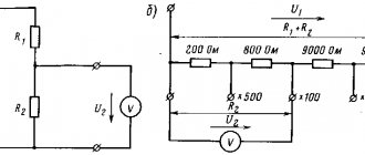
In order to calculate the total resistance of a circuit composed of active and inductive resistances connected to each other in parallel (Fig. 5, a), you must first calculate the conductivity of each of the parallel branches, then determine the total conductivity of the entire circuit between points A and B and then calculate the total resistance of the circuit between these points.
Figure 5. Circuit impedance when connecting active and reactive elements in parallel.
a) - parallel connection of R and L;
b) - parallel connection of R and C.
The conductivity of the active branch, as is known, is equal to 1/R, similarly, the conductivity of the inductive branch is equal to 1/ωL, and the total conductance is equal to 1/Z
Total conductivity is equal to the square root of the sum of the squares of active and reactive conductivity, i.e.
(7)
Reducing the radical expression to a common denominator, we get:
(8)
(9)
Formula (9) is used to calculate the total resistance of the circuit shown in Fig. 5a.
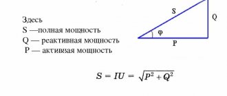
Finding the total resistance for this case can also be done geometrically. To do this, you need to construct a resistance triangle on the appropriate scale, and then divide the product of the lengths of the legs by the length of the hypotenuse. The result obtained will correspond to the total resistance.
Similar to the case discussed above, the total resistance with a parallel connection of R and C (Fig. 5b) will be equal to:
(10)
The total resistance can also be found in this case by constructing a resistance triangle.
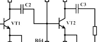
In radio engineering, the most common case is the parallel connection of inductance and capacitance, for example, an oscillatory circuit for tuning receivers and transmitters. Since the inductor always has, in addition to inductive resistance, also active resistance, the equivalent (equivalent) circuit of the oscillatory circuit will contain active resistance in the inductive branch (Fig. 7).
Figure 6. Equivalent circuit of an oscillatory circuit.
The impedance formula for this case will be:
(11)
Since usually the active resistance of the coil (R) is very small compared to its inductive resistance (ωL), we have the right to rewrite formula (11) in the following form:
(12)
In an oscillating circuit, the values of L and C are usually selected so that the inductive reactance is equal to the capacitive reactance, i.e., so that the condition is met
(13)
If this condition is met, the total resistance of the oscillatory circuit will be equal to:
(14)
where L is the inductance of the coil in H;
C is the capacitance of the capacitor in F;
R is the active resistance of the coil in Ohms.
This section of the basic TOE formulas is intended for beginners, both for students of higher educational institutions studying a physics course in electrical engineering, and simply for those interested in general electrical engineering /TOE/ with examples and comments from the author:
Before moving on to the formulas, I would like to draw your attention to the letter designation in TOE; in different textbooks on TOE, to put it mildly, the designation is quite arbitrary; there is no uniform requirement on this issue in electrical engineering. The difference in notation in complex numbers is especially noticeable (like mushrooms in the forest, as soon as they are not called in different places). Therefore, let’s immediately decide on the letter designation: