An experienced radio technician and amateur will find universal measuring equipment useful. The oscilloscope program for PC will help you study the shape of digital and analog signals, process and save research results. Such kits are used by amateurs and professionals when setting up, troubleshooting and repairing amplifiers, power supplies, and other equipment.
Visual presentation of information is a significant advantage of a software oscilloscope
About virtual oscilloscopes
Any personal computer (PC), even with “slow” processors and an outdated Windows XP operating system, is suitable for working together with specialized set-top boxes. However, a high-quality virtual oscilloscope connected to a standard USB port is expensive. A thorough search for suitable models of equipment on foreign online trading platforms does not solve the problem. Buying used equipment is associated with increased doubts and the absence of real guarantees.
At the same time, a superficial study of the topic is enough to understand the relative simplicity of this problem. Every PC has a sound card. Creating an input signal limiter regulator does not cause excessive difficulties. The measurements can be converted into a convenient form using a special simulator program. The instructions below will help you create a virtual oscilloscope quickly, without errors and extra costs.
| Shell version oscill.exe | 1.4.7 |
| Library version oscilink.dll | 1.4.3 |
| Version of the port checker TestBT.exe | 1.2.1 |
| Bluetooth communication library version wcl.dll | 6.11.9 |
| Archive size, bytes | 1241464 |
Download oscilnew.zip
Unzip to disk and run oscill.exe (you can display the shortcut on the desktop). There is no need to reinstall the USB driver.
Archive folder: oscill_new, for the purpose of simultaneous location on the computer of the basic and new versions.
Attention! Some new features of this software are available after updating the firmware to version 1.26.
Russification of menus and prompts: transfer *.lng files from the RUS folder to oscill.exe
Possible problems on Win7/8/10: msvbvm50, software installation, USB driver installation
a couple of demo dynamic waveforms (especially impressive when Memo is pressed)
New in the shell (oscill.exe):
1.4.7 (also see: new in the communication library with oscill v1.4.3).
+ Auto-calibration is possible every 2 seconds! Fixed crash when the buffer is empty: spectrum analyzer on startup, statistical analyzer when moving the mouse, search for signal levels. ! The file write message uses the system locale (for non-English names and paths). + GIF recording progress indicator - on top of other windows + running newoscill.bat (or oscill.exe with the reset key) erases the settings of all four possible oscills. + in the windows of the oscilloscope, spectro/statistical analyzer - up to 32 markers (measurements with the mouse) - with the Ctl button held down. For each, you can set and remember your own font color/size. ! when playing an OSC file - the V/div buttons display the recording status and its changes! “High Resolution” (HiRes) waveforms are saved to a CSV file as numbers 0...65535 (16-bit samples), and not separately high and low bytes.
1.4.6 (download link)
+ fixation of the oscillogram in the screen background (by the L button or automatic by synchronization) can disappear after a specified time: Display-Fixation-For Time! Fixed a crash in the standard deviation meter in HiRes on a strong signal! one of the error 13 type mismatch has been eliminated! a glitch in the registry (spectrum analyzer/stat analyzer window size) does not crash
1.4.5 (download link)
+ manual input of zero corrections and vertical deviation coefficients: Device-Ch1 setting. Corrections are stored in a special file with the name: “oscilloscope type + serial number.cor”. Corrections are recorded only in the active session, and they are read at the start of the session. + timing comparator delay compensation is now stored in a file for a specific oscilloscope, and not in the register. + Manual input of clock frequency correction, stored in the oscilloscope file. + The clock frequency of the oscilloscope is shown in Device-Clock with a discrete 10 kHz! Fixed a crash in the procedure for determining the 15/16 bit video mode in some rare cases. ! Fixed a crash in the procedure for calculating the standard deviation when shifting the oscillogram simultaneously with sweeps + in the automatic selection of sensitivity - the overload immediately increases V/div to the maximum, and then the sensitivity is selected depending on the input signal. Old option (gradual increase in V/div during overload) - available through the Device-CH1-OL mute setting. + in the automatic selection of sensitivity - the loss of a signal does not cause an automatic increase in sensitivity if you enable Device-CH1-If no signal + the menu item Display-Panels-Top menu removes the top menu + the “S” button not only moves the scan panel from the bottom to the left, but also removes Top Menu. + windows located on the second monitor restore their position upon next start! Fixed remembering the position of the device settings windows! in the recorder, double playback of frames with flickering in the title has been fixed + in the recorder, the Set Display Width option adjusts the number of cells on the screen - for recording! the recorder does not crash when trying to open a gigabyte recording (multi-day), a long opening is indicated. + pseudo-dual-channel has been improved: in standby mode the oscillogram is now recorded not in every synchronized sweep (as in auto mode), but in every second sweep. This allows you to get two waveforms on the screen for comparison without pressing the L button. ! fixed multiple measurements of a selected area using a stopped oscillogram + changing the boundaries of the selected area causes the meters to be recalculated even when the oscillogram is stopped
1.4.4 (download link) Under Wine via virtual COM - may not work, 1.4.3 is recommended
! turning on auto offset unlocks the offset slider + at the request of users, the tail of the marker line drawn first has been removed! The fast forward button in the recorder has been fixed + a slider has been added to the recorder that indicates the position on the multi-oscillogram and allows you to move around it in various ways (clicking, dragging, using the mouse wheel). + using the Y you can save the current oscillogram to a file with name=date+time, and the extension “.osc” + quick saving of all current settings to the file oscill.reg: Alt+S . Recovery: Alt+R . Reset (erase) all settings: Alt+E . ! Fixed remembering offset resolution! Tooltips above various indicators and controls have been expanded and corrected + the ability to replace built-in tooltips with a set of tooltips (for example, a different language) from the oscill.lng file has been implemented. The oscill.lng file has been prepared for the Russian language. + in meters you can disable the window rim: right mouse button - Border ! in the harmonic meter: calling the harmonics list again after turning off/on the spectrum analyzer does not close the application! the wait for the oscilloscope's response to a change in clock frequency has been extended + the width of the left field in front of the grid has been made variable to accommodate the voltage labels: Display-Labels-Width + language localization of the menu (the main one in the oscilloscope, spectrum analyzer, statistical analyzer - and context menus) from the oscill.lng file + “permanent markers”: when you hover the mouse over the left and right arrows of a selected section of the oscillogram, the time of the boundary pops up, and when the boundaries are active, a transparency of the interval between the boundaries is turned on between the arrows. + in the meter menu (right mouse button on the main value) an item has been added to reset this meter (Reset Avg/Min/Max, hot button R ), and an item to reset all meters (Reset All Meters, hot button F )! saving settings to a reg file uses the current positions and sizes of windows, and not the values at the time the application was launched.
Pseudo-second channel: + fixing the current oscillogram as a substrate for subsequent ones - hotkey L + automatic fixation of the oscillogram in the substrate when synchronization occurs (in Auto Sweep Mode): Display-Fixation-If trigger occurs + fixation of the oscillogram in the substrate when manually starting a new sweep: Display-Fixation-By Start key + changing the position of the oscillogram when fixing in the substrate: Display-Fixation-Shift by 4 div, swaps the upper and lower halves of the screen. For this function to work correctly, the oscillogram must be no more than 4 cells high and placed ALL of it either above or below the middle of the screen. With vertical stretch, the function is blocked. + change the color/brightness of the oscillogram when fixed in the substrate: Display-Fixation-Change Color.
1.4.3 (download link) - the latest version that works with the COM port via MSCOMM99! The unnecessary “OverNyquist...” message when closing the spectrum analyzer window has been removed. ! Disabling marks on the spectrum analyzer screen has been made instantaneous. + when the spectrum analyzer markers are disabled, the spectrogram expands! recording averaged instrument readings into a csv file is controlled by its own context menu item + a “standard deviation” meter has been added: Meters — Std deviation. ! color selection dialogs (screen, grid, markers) shows the original color of the object + you can set the color and font size of markers (measurements with the mouse): Display - markers + blanking of markers by sweep - made disable: Display - markers - Hide by sweep + in meters: current the value can be averaged from 50ms to 2s (to eliminate flickering numbers). ! The width of the meter window is now remembered accurately. + right mouse button on the “0” button (under the vertical displacement slider) - selecting the position of the zero line exactly on one of the nine grid lines. + the color of the “No trigger” banner shimmers, indicating scan starts without synchronization. ! The thickness of drawing in peak ROLL mode is controlled by CH1-PeakMode-Width, as in normal (not ROLL) + an alternative method of drawing a grid on the screen (for PCs on MAC OS X): Display - Grid - Alternate. The mesh is not taken from the substrate once, but is drawn in the foreground before and after each sweep.
1.4.2 (download link)
! Removed work with sockets (receiving remote control) due to false positives of antiviruses
1.4.1 (download link - Some antiviruses detect a threat in oscill.exe: forum)
+ an external 1:20 divider has been added to CH1-Divider + in the harmonics table of the SOI meter of the spectrum analyzer - in addition to the amplitude in volts, each harmonic has its level in dB. ! Fixed forced transition to Sin(x)/x during fast scan - it did not transition during linear interpolation. ! fixed “DC cycle avg voltage” meter + FPS meter moved to the Dispay - Show time menu (to match the meaning)! the number of fonts/codepage has been reduced to a minimum for compatibility with limited operating systems such as Windows XP embedded. + The screen grid can be dotted (Display - Grid - Dotted). + assigning additional and reassigning existing “quick buttons” using the keys.ini file + receiving commands over the network - support for various methods of external (remote) control (working with a WinLIRC server). ! Fixed playback of a multi-oscillogram from the *.osc file (associated with oscill.exe) when starting the shell with the command line. + due to the introduction of averaging, the resolution of TopRail, BotRail, Rail-to-rail meters has been increased. + a threshold has been introduced for the ratio of screen and real samples, from which interpolation is turned on: CH1-Interpolation-From ! fixed Interpolation-Auto switch + exporting instrument readings to the Windows clipboard (for each instrument the corresponding data type is registered in the clipboard) + recording instrument readings to a csv file. The current value (each sweep run) and/or the average value are recorded at specified time intervals corresponding to the averaging interval. + in instruments, when exporting/recording to a file, you can insert various time stamps, select the format of readings, and record only changes in readings.
Also: new in the communication library with oscill v1.2.1.
1.4.0 (download link) + in addition to 10 and 15 cells horizontally, you can now install from 6 to 15 cells. (shortcut: “W”; menu: Display-Divisions) + the scan panel can be installed on the left instead of the bottom (shortcut: “S”; menu: Display-Center). Useful for netbooks and wide LCD displays. + added to File-System info: indicator and graph of PC processor load, viewing and changing program priority. + in the harmonic meter (THD, THD) - automatic adjustment of the scan speed: “Adj T/div” (enabled by default). Selects the sampling frequency that is best for measuring SOI with a user-specified number of harmonics taken into account when measuring SOI. ! The FPS meter has been refined and made three-digit (oscilink.dll v1.2.0 allows you to raise PPS above 100). + right-click on the oscilloscope screen to open the menu for working with the image on the screen (static bitmap). + in the image working menu: the ability to set the current image as the background for the oscillogram (fix as backplane) + if the panels (scan, mode, channel) are hidden - you can show them on top of the oscillogram by clicking on the values T/div, mode, V/div at the top screen.
1.3.5 ! meters and spectrum analyzer analyze the entire array of samples, regardless of the horizontal stretch. + autoshift shifts the oscillogram up and down in multiples of the scale cell. ! Autosensitivity, when increasing sensitivity, sometimes increased unnecessarily, then corrected it by lowering it. Now he does it right right away. ! in the recorder, recording to a file starts only after selecting the file name (does not write the beginning to memory) + when the recorder window is closed, the continuous automatic scanning mode is restored. + in the recorder - circular playback mode + default interpolation - Line, but on fast scans (Fd>Fbw/3) sin(x)/x is forced on (disable: CH1-Interpolation-Auto) ! Fixed a crash on a certain PC when saving all settings to a *.reg file! Fixed a bug when expanding the main window from the tray to which a minimized meter is attached. ! fixed crash when selecting “Acq per plot” = 20
1.3.4 (download link)
! Fixed firmware incompatibility with a comma instead of a dot in the version.
1.3.3 ! Fixed the operation of the P hotkey (peak mode), the V hotkey switches display options (dots/lines) in a circle. + hot buttons: Alt+Q - shutdown. + added 20x horizontal stretching + when drawing with dots - you can disable the display of interpolated samples in the menu. + The thickness of the oscillogram drawing line and the size of the points (samples) are set separately. ! Support for the third and fourth simultaneously running oscilloscopes has been fixed. — memorization of vertical and horizontal extensions is disabled. ! entering a space in CH1-Probe-UserScale does not lead to an error, but removes the vertical dimension. ! Removing the window hotkey does not crash. + replacing the cursor with an arbitrary one, loaded from the file cursor.cur or cursor.ico (place in the directory with oscill.exe). ! A crash has been fixed in the recorder when performing operations on an empty buffer and the number of frames>32767. Saving a large record to a file has been accelerated. + in the recorder it is possible to record directly to a file (bypassing the buffer) and decimation: recording every X frame + the recorder window can be pinned on top of the rest. ! Fixed two rare crashes in meters
1.3.2 + indication of the slew rate in cursor measurements (tooltip on the amplitude cursor mark). + indication (at the top of the screen) of work in ROLL mode (transferring samples to a PC directly during digitization).
1.3.1 (download link) ! Fixed a crash when refusing to enter a custom division factor. ! Free sweep and infinite synchronization wait - available from firmware 1.25. ! It is possible to move the oscilloscope window to a second monitor located to the left of the main one. + The second oscill, when translated to the clipboard, uses the “Oscill 2 Sample Data” data type. ! Broadcasting packets to the clipboard does not clear the clipboard
1.3.0
+ auto synchronization level works even when overloaded. + smooth adjustment of time/division within adjacent values. + automatic setting of sensitivity and/or beam offset for the best signal display. + Fixing the oscilloscope clock frequency (to bypass parasitic ADC delays): Device — Cljock setting — Fix max clock. + automatic resampling when changing the number of samples (from switching normal/wide screen). + in normal/averaging modes, 256 samples per cell are available (with an oscillogram length of 7 cells). + support for free scan (without synchronization, “Free Run”) - requires firmware from 1.25. + Support for scanning with a long wait for synchronization - requires firmware from 1.25. + in the Display menu - submenu Panels, allows you to select displayed panels (scan, channel). + automatic setting of the sweep speed to obtain a specified (from 1 to 30) number of signal edges. ! Fixed oscillogram shift in wide mode when stretched horizontally and with a small number of samples. + in the CH1 - Divider menu, you can set an arbitrary division/gain factor of the external device, and also replace the voltage symbol (“V” - volts) with a one- or three-letter designation of the measured value. ! Fixed a crash when expanding a minimized window located on a second monitor (in Windows desktop extension mode). + button to forcefully terminate a long operation (for example, waiting forever for synchronization). + indicator waiting for a response from oscill (colored line at the bottom of the MODE panel). + cursor measurements on the oscillogram show not only the duration of the interval, but also the corresponding frequency.
1.2.9 ! Fixed selection of external divider 1/10 in the channel menu.
1.2.8 + warning when RIS is disabled. ! Freezing when multi-pass digitization is enabled in peak mode with active rail-to-rail voltage measurement has been fixed. previous changes (2008..2010)
New in the communication library (oscilink.dll):
1.4.3 ! repeated access to bluetooth is blocked if the active search for bt.oscill lasts for a long time
1.4.2
+ new Bluetooth library WCL 6.11.9 is supported, as well as wcl2wbt (for the Widcomm stack)! Thanks to the new WCL, the pairing window has been eliminated for the MS stack on WinXP when there is no oscill in the Bluetooth area! Fixed an error with “COM via WCL” that occurred due to a previous change to the WCL library.
1.4.1
! work via virtual COM ports has been changed (starting from 1.4.0 - via API)! The oscill firmware update did not work on a certain PC with a USB3 DLL driver, fixed. ! when an error was selected in the USB3 driver menu (on a real USB2), large packets were not passed through, fixed. + new WCL 6.10.5 is supported, as well as wcl2wbt (for the Widcomm stack)! in the search for bt.oscill via WCL - waiting for the late detection of the bluetooth name of the found oscill + the latest bluetooth oscill is available in the Port- menu under its name! receiving data from bt.oscill via WCL - using a timer (the Display-Show time setting now works). + alternative work with COM ports (bluetooth, VCP USB drivers) via WCL. Included in Link-Port-Use WCL for COM.
1.4.0 + work with Bluetooth oscill via WCL (Wireless Communication Library): support for bluetooth stacks Microsoft, BlueSoleil, Toshiba, WidComm. Now there is no need to assign and use a COM port, Oscill is found automatically by name, and pairs automatically with the default code 0000. In addition to simplifying the connection, WCL increases FPS. To communicate via Bluetooth, you now just need to select the WCL Bluetooth item in the Link-Setup-Port menu. +work with the COM port has been transferred from mscomm to API to simplify installation on a PC. Also thanks to this, it became possible to work with bt.oscill via the Bluetooth stack “Sybase iAnywere Blue Manager”. ! support for different (in terms of installation/measurement time) registers, for cases of extended installation of the clock frequency synthesizer at low temperatures. + language localization of menus and tips from the oscilink.lng file! Fixed initial autosearch with user-selectable connection for two or more oscills on a direct DLL driver.
1.3.0 + support for new USB drivers (Ver 3.x) via SiUSB32.dll. Oscilink itself determines the driver version, but you can help it with this: Port - USBdriver - Auto/v2/v3 + when you hover the mouse over the port number, the DLL and driver versions are shown. + in the list of ports - before COM there is a port type (conditional letter) + checking the bluetooth port is placed in a separate thread (TestBT.exe) and does not slow down the shell + auto-detection of the bluetooth port of the Toshiba stack! user's indication that the port is bluetooth is saved during the next shell launches + tracking of oscill connection/disconnection is accelerated + periodic auto-check of oscill connection - made disableable: Mode-AutoConnect-Periodic-Enable + you can separately disable testing of the BT port (so as not pull Bluetooth stack): Mode-AutoConnect-Periodic-BT port
1.2.1
! missing packets are excluded if their length is >512 and redundant interrupt reception is enabled (introduced optionally in v1.2.0) + diagnostic entry to the exchange file with oscill. + setting the frequency of data reception in ROLL mode (real-time oscillogram with slow sweep)
1.2.0 + when working through a COM port (including virtual COM-USB ports), interrupt reception is possible: Timing menu - COM receive event, while the maximum PPS on a multi-core CPU is twice as high as before (128 versus 64). On a single-core - PPS is possible up to 200. In Windows 98/ME - PPS also doubles, from 25 to 50. ! The accuracy of the PPS counter has been increased (especially at high values), the counter has been made three-digit for PPS>99 + the ability to clock from the Multimedia Timer has been introduced, which potentially raises PPS to the limit of PC performance. Helps on Linux. + the ability to clock from the Queue Timer has been introduced (except for Windows98/ME), which potentially raises PPS to the limit of PC performance. Helps on Linux.
1.1.3 ! the command pipeline has been improved to quickly process repetitive user actions! returned window position memorization
1.1.2 ! auto-detection of PL2303HX and resolution of 1843200 baud - through the menu: Link - Setup - Port - Find port. + detection of short circuit between RX and TX: “loopback detected” message.
1.1.0 + monitoring the physical connection of the oscilloscope to the USB port. + auto-connection after physically connecting the oscilloscope to the USB port (enabled by the user: Mode - Connect by Insert). + packets per second meter (OBEX-PPS). + support for virtual Bluetooth ports - special settings are enabled through the Speed menu (as a rule, the BT port is detected automatically). + command in oscill to initialize the bluetooth module (name, PIN, speed). + COM and USB ports - only those detected on the PC are shown (can be disabled). ! Clearing the input buffer before re-requesting a broken packet. + forced termination of the long wait for a response from Oscill, with sending a special command to Oscill. + auto port search works with any Prolific drivers (not only those customized for Oscill). + support for speed 1843200 baud - only for later modifications of the Prolific usb-uart bridge: PL2303HX.
previous changes (2008…2010)
Functional Features
Oscilloscope - concept and design of the device
Even a low-power computer can become the basis of the equipment. In some situations, laptops are preferable. Portable models can be used to troubleshoot problems in cars.
Other functional features worth noting:
- a coupling capacitor is installed in the standard input circuit of the audio card, so without disassembling and making changes to the circuit, it will be possible to display only the variable component of the signal on the screen;
- minimum amplitude 0.5-2 mV (determined by the technical characteristics of the audio path);
- the maximum input signal is chosen with virtually no restrictions, since for several tens or hundreds of volts you only need to create an appropriate voltage divider;
- The frequency range is also determined by the basic TX of the computer, usually from 10 Hz to 22 kHz.
Device diagram and assembly
There are many circuits for making a digital USB oscilloscope with your own hands. Not all are accessible to the inexperienced radio amateur. The easiest way is to assemble devices based on a sound card , since here you only need to assemble a divider to increase the threshold of the incoming voltage.
USB connection
A USB oscilloscope is difficult to make with your own hands, but it is a high-precision device with a large frequency range. Parts for it can be purchased in a store or ordered online. The list of spare parts is as follows:
- double-sided board with ready-made tracks;
- ADC AD9288−40BRSZ;
- the system is assembled on a CY7C68013A processor;
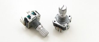
- resistors, transformers, capacitors, chokes - the ratings are indicated on the diagram;
- soldering iron and hair dryer, soldering paste, flux and solder;
- wire with a cross-sectional area of 0.1 mm2 and varnish coating;
- toroidal core for making a transformer;
- memory chip EEPROM flash 24LC64;
- relay with control voltage no more than 3.3 V;
- operational amplifiers AD8065;
- DC-DC converter;
- USB connector;
- fiberglass;
- connectors for probes, housing for the board.
How to clean your computer keyboard at home
The device diagram is shown below.
Since double-sided mounting is used, it a board with tracks . You need to contact the production association that produces such products and place an order with the following conditions :
- fiberglass on which the diagram will be marked must have a thickness of at least 1.5 mm;
- the thickness of the copper tracks is at least 1 ounce (OZ) or 35 microns;
- through metallization of holes;
- Tinning of contact pads for better soldering of elements.
Once you have received your order, you can begin assembly. First, a DC-DC converter to produce two constant voltages: +5 V and -5 V. It is manufactured separately from the main device, and then connected with a shielded cable.
Next, carefully solder the circuit elements . Be especially careful when soldering microcircuits, do not allow the temperature of the soldering iron to increase above 300°C.
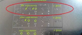
Having placed the manufactured device in the case, connect it to the computer via a USB connector. After this, bridge jumper JP1 .
Using an audio card
An oscilloscope from an external sound card is a low-budget and easy-to-make oscilloscope for a computer or laptop. Most suitable for beginner radio amateurs. You can use either an external or internal audio device.
voltage for the computer's internal sound card should not exceed 0.5-2 V. To measure a signal with an amplitude greater than 2 V, it is necessary to feed it to the computer through a voltage divider . The attenuator is assembled according to the following scheme.
The supplied voltage is reduced by 100, 10 or 1 times, depending on the value. To do this, the probes are inserted into the appropriate connectors. Fine tuning occurs through a trim resistor . Diodes protect against accidental voltage supply of more than 2 V.
Place the structure in a metal box to eliminate possible interference . The wire connected to the sound card must be short with copper braiding. To create a second channel, you need to duplicate the device. If the card has several inputs, then choose the one with the lowest internal resistance.
10 good reasons to upgrade to Windows 10
Below is a circuit using an external USB sound card that costs about $2.
In addition to the adapter you will need:
- resistance at 120 kOhm:
- mini Jake connector;
- measuring probes.
After purchasing all spare parts, follow these steps:
- Open carefully adapter so as not to break the latches. There will be a small circuit board inside.
- Remove capacitor C6 and put a 120 kOhm resistor in its place.
- Solder mini Jack connectors to the probes instead of the original ones and insert them into the adapter.
- Download the archive with device drivers and unpack it into a folder. Insert the gadget into the computer.
- The computer will ask drivers for a new device.
- Install them by specifying the path to the folder.
- Click on the “Further» to install drivers.
The oscilloscope must be configured before use.
Converting a Computer to an Oscilloscope
DIY oscilloscope
After clarifying the initial computer data and personal needs, they begin to select an electrical circuit.
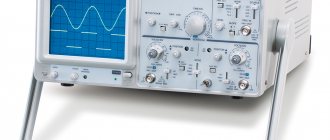
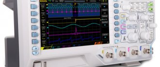
To get acquainted with professional solutions, you can study the designs of serial measuring instruments
Set-top box diagram
For high-quality reproduction without extensive practical experience, it is better to choose relatively simple designs. However, the electrical circuit presented below is quite capable of ensuring minimal signal distortion while simultaneously performing protective functions.
This adapter circuit can be created quickly without unnecessary difficulties
Description:
- the set-top box resistors are evaluated in conjunction with the Rin of the computer in order to correctly calculate the divider parameters;
- capacitors equalize the frequency response;
- Zener diodes installed in the manner shown in the figure prevent damage to the computer’s audio input when a high-amplitude signal is supplied (switch position “1:1”);
- additional current protection is provided by R1.
You can hardly count on complete passport data, especially if you have old computer equipment. Most likely, you will have to measure the impedance at the sound card input. To do this, a reference signal (50 Hz, sinusoid) is created at the output of the same block using a special “Virtual Generator” program. The following calculation is performed using the formula:
Rx=R1*(U1/(U2-U1)).
Example:
60*(120/(520-120))= 18 kOhm.
Knowing the input resistance, create a voltage divider using one of the presented circuits
For your information. By installing a “tuning” resistor in parallel, you can precisely adjust the parameters of the divider.
Set-top box collection
To eliminate the parasitic influence of external electromagnetic radiation, the set-top box is placed in a metal case. It can be created from a suitable duralumin sheet with a thickness of 1.5-2 mm. A CP-50 type connector is attached to the input so that standard probes can be connected without problems. The output is a flexible cable with a Jack plug that matches the input jack of the computer audio card. For assembling a simple electrical circuit, surface-mounting technology is quite suitable.
Radio amateur
Digital Oscilloscope V3.0 is a popular amateur radio program that will turn your computer into a virtual oscilloscope
Good afternoon, dear radio amateurs! Welcome to the website “Amateur Radio”
Today on the site we will look at a simple amateur radio program that turns a home computer into an oscilloscope .
There are two ways to turn a personal computer into an oscilloscope . You can buy or make a set-top box that connects to your PC. The set-top box will be an ADC, software-controlled. And install the appropriate program on your PC. But this is a costly method. The second method is cost-free; any PC already has an ADC and a DAC - a sound card. Using it, you can convert your computer into a simple low-frequency oscilloscope , just by installing software, and you will have to solder a simple input divider. There are quite a few such programs. Today we will look at one of them - Digital Oscilloscope V3.0 .
Digital Oscilloscope V3.0 (149.8 KiB, 75,599 hits)
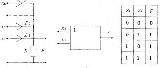
After starting the program, a window will appear on the screen that looks very similar to a regular oscilloscope. The linear input of the sound card is used to supply the signal. You usually need to apply a signal of no more than 0.5-1 volt to the input, otherwise a limitation occurs, so you need to solder the input divider according to a simple circuit, as shown in Figure No. 2.
KD522 diodes are needed to protect the sound card input from too much signal. After connecting the circuit and input signal, you need to turn on the oscilloscope. To do this, click the RUN field with the mouse and select START or click the triangle in the second row from the top of the window. The oscilloscope will show the signal. The frequency and period of the signal will be displayed in the lower right corner of the screen. But the voltage shown by the oscilloscope may not correspond to reality. When setting up an input divider, you need to try to set the division coefficient with a variable resistor so that the voltage shown on the screen is as realistic as possible.
Purpose of governing bodies. TIME/DIV – time/division; TRIGGER – synchronization; CALIB – level; VOLT/DIV – voltage/division. And one more advantage of this program is that the oscilloscope has a memory - you can stop the work, and an oscillogram will remain on the screen, which can be saved in the PC memory or printed.
Similar articles:
1. SoundCard Oszilloscope – Computer – oscilloscope, signal generator, spectrum analyzer
The best oscilloscope software for Windows PC
The following sections provide brief overviews of popular specialized programs. When choosing, you should pay attention to ease of learning, interface language, and other details, taking into account the needs of a particular user.
FrequencyAnalyzer
The program was created for processing audio signals. It is permissible to change the measurement frequency. User-selectable 8 (16) digit conversion helps establish the required accuracy. The disadvantage is the lack of a Russified version.
Winscope
This online oscilloscope does more than just show the signal. When you select the appropriate mode, Lissajous figures are displayed on the screen. The user can examine the spectral distribution in the range from 20Hz to 20kHz.
Sound oscilloscope
The 2ray Oscilloscope is well suited for studying two signals. If necessary, waveforms can be saved as graphic files. The clear interface simplifies the use of the program.
Oscilloscope Spectrum in real time
Multi-Instrument contains not only an oscilloscope, but also a generator. This software suite is complemented by a spectrum analyzer. Such equipment is suitable for complex testing of radio equipment.
Programs that emulate the operation of an oscilloscope
Virtual oscilloscopes process signals received at the input of a computer or laptop . These programs have an interface similar to the screen of a real oscilloscope. Some applications are designed to work with devices based on sound cards, others interact with USB oscilloscopes.
Programs running through audio input:
- Digital Oscilloscope;
- SoundCard Oszilloscope;
- Russian development "Avangard".
Software for USB oscilloscopes:
- Aktakom OscilloscopePro.
- Simplescope.
All virtual devices are two-channel , equipped with frequency generators and analyzers. The measurements and oscillograms can be saved on a PC. Usually they do not need to be installed. After unpacking the archive and launching the program, the interface of a real oscilloscope with settings regulators appears.
Working methods
A computer is a digital device, so to measure an analog parameter it is necessary to convert the signal into discrete form . For this, an ADC is used - an analog-to-digital converter. A DAC (digital-to-analog converter) is used to output data.
The computer's sound card samples incoming analog signals that are connected to the LINE IN and MIC inputs.
Therefore, the audio card can be used as an ADC to supply the measured signal to a computer or laptop. Since a person hears sound in the range of 4Hz-20kHz, then, accordingly, the audio card operates in the low-frequency spectrum . The resulting oscilloscope will also operate in the specified range.
Another drawback in the operation of a “sound” oscilloscope is the limitation on the voltage supplied to the input. It should be within 0.5V for MIC input and up to 2V for LINE IN. Connecting a signal with an amplitude of more than 2V will damage the sound card or computer.
Due to the design features of the audio card - the presence of a decoupling capacitor at the input, the direct component of the electric current will not be shown on the oscilloscope. But using the app, you can measure it. It is better to send the signal to the LINE IN input, since it has the lowest noise level. The minimum signal level that can be measured is about 1 mV.
The use of such oscilloscopes is limited in frequency . They can take readings from amplifiers, tape recorders, various audio devices, as well as microcircuits operating at frequencies up to 20 kHz.
Yandex and Google - which is better and what are the differences
At high frequencies, USB oscilloscopes with more capabilities are used. The disadvantage of such devices is their high price.
Use in everyday life
During operation, the following recommendations should be used:
- the computer together with the set-top box is grounded before performing measuring operations;
- use a range suitable for a certain signal amplitude;
- stop working if the electrical insulation is damaged or other dangerous faults are detected.
The presented oscilloscopes for PC, when properly assembled and configured, provide fairly high accuracy. However, we must not forget that even specialized devices in this category are intended rather to study the shape of signals. Such problems can be solved using the equipment discussed in the publication.