Added March 21, 2022 at 1:10 pm
Save or share
Learn how to use an incremental rotary encoder in an Arduino project.
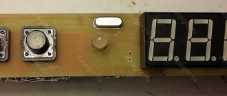
A rotary encoder is an electromechanical device that converts rotary motion into digital or analog information. It is very similar to a potentiometer, but can be rotated indefinitely, either clockwise or counterclockwise. There are several types of rotary encoders. The two main types are absolute and relative (incremental) encoders. While an absolute encoder outputs a value proportional to the current shaft angle, an incremental encoder outputs the shaft's pitch and direction. Rotary encoders are becoming more and more popular in consumer electronics, especially as control knobs, in addition to applications in many other fields. They replace potentiometers and navigation buttons where fast navigation, setup, data entry and menu selection are required. Some encoders also include a built-in button that creates an additional input to the processor that can be used as another user command in the control interface. In the picture below you can see a typical incremental rotary encoder with a power button.
Incremental rotary encoder
In this article, we will show you how to use an incremental rotary encoder in an Arduino project. We will explain how to deal with contact bounce and interpret encoder signals in a microcontroller program using interrupts.
Incremental encoder quadrature output signal
An incremental rotary encoder produces two output signals as the shaft rotates, also called quadrature output. Depending on the direction, one signal is ahead of the other. Below you can see the output waveform of an incremental rotary encoder and the expected bit sequence.
Signals at the outputs of an incremental rotary encoder when the shaft rotates clockwise and counterclockwise
As can be seen from the figure, both outputs are initially in the logical one state. When the encoder shaft begins to rotate in a clockwise direction, the state at output A drops to logic zero first, and then output B follows with a lag. When rotating counterclockwise, the opposite happens. The time intervals on the signal diagram depend on the rotation speed, but the signal lag is guaranteed in any case. Based on this characteristic of an incremental rotary encoder, we will write a program for Arduino.
Filtering contact bounce of a mechanical encoder
Mechanical encoders have built-in switches that generate a quadrature output signal during rotation.
Contact bounce at the output of a mechanical encoder
When dealing with encoder signals, the main problem is contact bounce. It causes erroneous determination of the direction of rotation and the amount of rotation of the encoder shaft and makes the use of encoders problematic. We can get rid of contact bounce by filtering it in a program or using additional filtering schemes.
Noise filtering in microcontroller software is one filtering option, but it has some disadvantages. You need to write more complex code to handle the noise. Filtering will take up processing time and introduce delays into the main program thread. You may need to set timers to ignore contact bounce intervals. In the end, you may not be able to get a satisfactory and reliable result.
Noise filtering with additional hardware is simpler and stops noise at its source. You will need a first order RC filter. In the picture below you can see what the signal looks like after using an RC filter.
RC filter and signal shape at its output
The RC filter slows down the fall time and rise time and provides hardware debouncing. When selecting a resistor-capacitor pair, you must consider the maximum speed. Otherwise, the expected encoder response will be filtered.
Required Components
Hardware
- Microcontroller ATmega8 (buy on AliExpress).
- Programmer AVR-ISP (buy on AliExpress), USBASP (buy on AliExpress) or another similar one.
- Incremental encoder (Rotary Encoder) (buy on AliExpress).
- Capacitor 100 nF (3 pcs.) (buy on AliExpress).
- Capacitor 1000 uF (buy on AliExpress).
- Resistor 220 Ohm (2 pcs.) (buy on AliExpress).
- 1 kOhm resistor (buy on AliExpress).
- LED (8 pcs.) (buy on AliExpress).
- Power supply with a voltage of 5 Volts.
Software
- Atmel Studio version 6.1 (or higher).
- Progisp or flash magic (optional).
Simple application
We will create an application demonstrating how to use a rotary encoder in an Arduino project. We will use the encoder for navigation, data entry and selection. Below is a schematic diagram of the application.
Schematic diagram of an example application using a rotary encoder on Arduino
The circuit is based on the Arduino Uno board. The LCD display of Nokia 5110 is used for the graphical interface. A mechanical rotary encoder with a button and RC filters is added as controls.
Assembled diagram of an example of using a rotary encoder on Arduino
We will develop a simple software menu in which we will demonstrate the operation of a rotary encoder.
Processing Encoder Signals Using Interrupts
Encoder signals must be detected and interpreted in the program as quickly as possible so as not to block the main program flow. We can detect signals by polling in the main loop, or by using interrupts. Polling is not efficient because you need to reserve time and resources in the main loop, which introduces additional delays. Using interrupts is a faster and more cost-effective solution. We'll show you how to use interrupts to process encoder signals.
The Atmega328 has two types of interrupts that can be used for this purpose; external interrupt and output change interrupt. The INT0 and INT1 pins are assigned to an external interrupt, and PCINT0-PCIN15 are assigned to a pin change interrupt. An external interrupt can detect whether the input signal is falling or rising and can be triggered under one of the following conditions: rising, falling, or switching. There are many more hardware resources available for the pin change interrupt, but it cannot detect rising and falling edges, and it is called when any logic state change (toggle) occurs on a pin.
To use the pin change interrupt, connect the encoder A and B turn outputs to A1 and A2, and the button output to Arduino pin A0, as shown in the circuit diagram. Set pins A0, A1 and A2 to input mode and turn on their internal pull-up resistors. Enable the pin change interrupt in the PCICR register and enable interrupts for pins A0, A1 and A2 in the PCMS1 register. If any change in logic state is detected on one of these inputs, ISR(PCINT1_vect) (Pin State Interrupt) will be called.
Since the pin change interrupt is called for any logical change, we need to monitor both signals (both A and B) and detect rotation when the expected sequence is received. As can be seen from the signal diagram, clockwise movement generates A = …0011… and B = …1001…. When we write both signals to bytes seqA and seqB, shifting the last read to the right, we can compare these values and determine the new rotation step.
You can see part of the code that includes the initialization and pin change interrupt function.
void setup() { pinMode(A0, INPUT); pinMode(A1, INPUT); pinMode(A2, INPUT); // Enable internal pull-up resistors digitalWrite(A0, HIGH); digitalWrite(A1, HIGH); digitalWrite(A2, HIGH); PCICR = 0b00000010; // 1. PCIE1: Enable state change interrupt 1 PCMSK1 = 0b00000111; // Enable state change interrupt for A0, A1, A2 } void loop() { // Main loop } ISR (PCINT1_vect) { // If the interrupt is caused by a button if (!digitalRead(A0)) { button = true; } // If the interrupt is caused by encoder signals else { // Read signals A and B boolean A_val = digitalRead(A1); boolean B_val = digitalRead(A2); // Write signals A and B into separate sequences seqA <<= 1; seqA |= A_val; seqB <<= 1; seqB |= B_val; // Mask the four most significant bits seqA &= 0b00001111; seqB &= 0b00001111; // Compare the stored sequence with the expected sequence if (seqA == 0b00001001 && seqB == 0b00000011) { cnt1++; left = true; } if (seqA == 0b00000011 && seqB == 0b00001001) { cnt2++; right = true; } } }
Using an external interrupt makes the process simpler, but since this interrupt only has two pins assigned to it, you won't be able to use it for other purposes if you occupy it with an encoder. To use an external interrupt, you must set pins 2 (INT0) and 3 (INT1) to input mode and turn on their internal pull-up resistors. Then select the falling edge option to trigger both interrupts in the EICRA register. Enable external interrupts in the EIMSK register. When the encoder shaft begins to rotate, first the leading signal drops to logical zero, and the second signal remains at logical one for some time. Therefore, we need to determine which of the signals is in the logical one state during the interrupt. After the leading signal has fallen to logic zero, after some time the second signal will also fall to logic zero, causing another interrupt. But this time and the other (leading) signal will be at a low logic level, which means it is not the start of rotation, so we ignore it.
Below you can see part of the code that includes the initialization and external interrupt handling function.
void setup() { pinMode(2, INPUT); pinMode(3, INPUT); // Enable internal pull-up resistors digitalWrite(2, HIGH); digitalWrite(3, HIGH); EICRA = 0b00001010; // Select call on falling edge EIMSK = 0b00000011; // Enable external interrupt } void loop() { // Main loop } ISR (INT0_vect) { // If the second signal is in the logical one state, then this is a new rotation if (digitalRead(3) == HIGH) { left = true ; } } ISR (INT1_vect) { // If the second signal is in the logic one state, then this is a new rotation if (digitalRead(2) == HIGH) { right = true; } }
Breadboard for checking code for working with an incremental rotary encoder on Arduino
The complete code for the Arduino sketch, including the main loop, is below:
#include #include #include volatile byte seqA = 0; volatile byte seqB = 0; volatile byte cnt1 = 0; volatile byte cnt2 = 0; volatile boolean right = false; volatile boolean left = false; volatile boolean button = false; boolean backlight = true; byte menuitem = 1; byte page = 1; Adafruit_PCD8544 display = Adafruit_PCD8544(13, 12,11, 8, 10); void setup() { pinMode(A0, INPUT); pinMode(A1, INPUT); pinMode(A2, INPUT); // Enable internal pull-up resistors digitalWrite(A0, HIGH); digitalWrite(A1, HIGH); digitalWrite(A2, HIGH); // Turn on the LCD backlight pinMode(9, OUTPUT); digitalWrite(9, HIGH); PCICR = 0b00000010; // 1. PCIE1: Enable state change interrupt 1 PCMSK1 = 0b00000111; // Enable state change interrupt for A0, A1, A2 // Initialize LCD display.setRotation(2); // Set orientation LDC display.begin(60); // Set LCD contrast display.clearDisplay(); // Clear display display.display(); // Apply changes sei(); } void loop() { // Create menu pages if (page==1) { display.setTextSize(1); display.clearDisplay(); display.setTextColor(BLACK, WHITE); display.setCursor(15, 0); display.print("MAIN MENU"); display.drawFastHLine(0,10,83,BLACK); display.setCursor(0, 15); if (menuitem==1) { display.setTextColor(WHITE, BLACK); } else { display.setTextColor(BLACK, WHITE); } display.print(">Contrast: 99%"); display.setCursor(0, 25); if (menuitem==2) { display.setTextColor(WHITE, BLACK); } else { display.setTextColor(BLACK, WHITE); } display.print(">Test Encoder"); if (menuitem==3) { display.setTextColor(WHITE, BLACK); } else { display.setTextColor(BLACK, WHITE); } display.setCursor(0, 35); display.print(">Backlight:"); if (backlight) { display.print("ON"); } else { display.print("OFF"); } display.display(); } else if (page==2) { display.setTextSize(1); display.clearDisplay(); display.setTextColor(BLACK, WHITE); display.setCursor(15, 0); display.print("ENC. TEST"); display.drawFastHLine(0,10,83,BLACK); display.setCursor(5, 15); display.print("LEFT RIGHT"); display.setTextSize(2); display.setCursor(5, 25); display.print(cnt1); display.setCursor(55, 25); display.print(cnt2); display.setTextSize(2); display.display(); } // Perform an action if a new command is received from the encoder if (left) { left = false; menuitem—; if (menuitem==0) { menuitem=3; } } if (right) { right = false; menuitem++; if (menuitem==4) { menuitem=1; } } if (button) { button = false; if (page == 1 && menuitem==3) { digitalWrite(9, LOW); if (backlight) { backlight = false; digitalWrite(9, LOW); } else { backlight = true; digitalWrite(9, HIGH); } } else if (page == 1 && menuitem==2) { page=2; cnt1=0; cnt2=0; } else if (page == 2) { page=1; } } } ISR (PCINT1_vect) { // If the interrupt is caused by a button if (!digitalRead(A0)) { button = true; } // Or if the interrupt is caused by encoder signals else { // Read signals A and B boolean A_val = digitalRead(A1); boolean B_val = digitalRead(A2); // Write signals A and B into separate sequences seqA <<= 1; seqA |= A_val; seqB <<= 1; seqB |= B_val; // Mask the four most significant bits seqA &= 0b00001111; seqB &= 0b00001111; // Compare the stored sequence with the expected sequence if (seqA == 0b00001001 && seqB == 0b00000011) { cnt1++; left = true; } if (seqA == 0b00000011 && seqB == 0b00001001) { cnt2++; right = true; } } }
You can see the encoder in action in the video below:
That's all! I hope the article was useful. Leave comments!
Original article:
- Editorial Team. How to Use a Rotary Encoder in an MCU-Based Project
Microcontroller port reading and software anti-interference (digital filter)
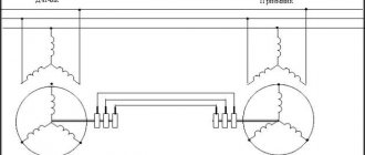
Let's consider the processing of port PA.
In total, the EP50S8-720-2F-N-5 encoder has 10 conductors (10 bits) to provide 720 numbers per revolution. Now it will read each of the bits of the port (don’t forget to invert the port ~GPIOA->IDR - since we have pulled up resistors to the power supply). We shift the least significant bit connected to PA4 by 4 bits to the right to obtain the correct final number (GPIO_IDR_IDR4>>4). And we shift the most significant bit to the left by 9 (GPIO_IDR_IDR0<<9), because The corresponding encoder wire is connected to PA0, and should correspond to 10 bits. It would be possible to connect some wire to another port, for example PB, and perform the procedure for reading from the PB0 leg: ((~GPIOВ->IDR & GPIO_IDR_IDR0)<<9). This is the universality of the reading procedure.
The for(uint8_t i = 0; i <= 200; i++) loop is necessary to confirm 200 times that the encoder value is set to 55. This is a kind of digital filter against interference that can inevitably occur in a 10-wire parallel communication line.
It would be possible to use shift registers and read the number into the STM32 microcontroller via the SPI protocol. But that is another story.