Hello, dear readers of Datagor.ru!
Today I will talk about my project, which was born due to the failure of one of the most important parts of my refrigerator - the thermostat. The automation stopped working and kept the refrigerator compressor on all the time, bringing the temperature inside to −4°C instead of the standard +5°C! Minus temperature in the refrigerator, we get a piece of ice from the soup! And in the freezer part it was generally -25°C. The time has come for me to study the principles of operation of refrigeration units and assemble my own digital thermostat, with indication, settings and time-based compressor protection. We will talk about this further. Let's get started!
↑ A little history
My refrigerator is already a good 20 years old and during this time it has managed to change two motors and one thermostat, visited two workshops and now this “Frankenstein’s monster” has completely stopped turning off. From experience I can say that I really don’t like such thermostats; their mechanical components are quite capricious. I also came across unique craftsmen; they repaired one part of the refrigerator and broke another. For example, after the repair, the “interior” light stopped turning on when I opened the door. “Do you want it done well? Do it yourself!"
↑ Study of the refrigeration issue and temporary solution
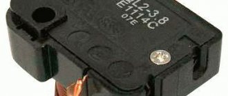
I disassembled the thermostat housing and let's study how it should work. When the temperature drops, the freon in the thermostat tube contracts and begins to pull the contacts of the compressor relay, from which the relay snaps off and turns off the compressor. After increasing the temperature, the reverse process occurs. So I should connect my relay to the contacts instead of the thermostat.
Refrigerator thermostat
Food is starting to spoil! Calling a specialist to work on the refrigerator for a couple of weeks (and I have such specialists in my city) is not an option, what should I do? It is necessary to periodically pull the plug from the socket, simulating the operation of the thermostat! This masochism was enough for me for one day, so I needed a convenient solution and in the evening I assembled a regular microcontroller on/off timer-relay literally on a tray and this is no joke.
Refrigerator thermostat prototype
Works! Its task is to stupidly turn on the compressor for 15 minutes and turn it off for 45. I took the power from a pulse generator from a broken DVD player, and two outputs of 12 and 5 Volts were successfully discovered in it. I stuck the relay into the extension cord and pressed everything with the speakers. An elegant temporary solution has arrived!
How to replace correctly
When performing work to replace a faulty thermostat, you need to follow the instructions to avoid common mistakes. Violation of the rules for installing a new component can cause incorrect operation of the equipment and cause breakdowns of other parts.
Dismantling
When starting to dismantle the thermostat, be sure to unplug the refrigerator from the outlet. Then you should find the location of the component depending on the type of equipment. Usually, for dismantling it is enough to unscrew the adjusting knob, remove the fasteners and the protective cover of the housing.
↑ Diagram of my thermostat
Now there is “time to think” and look for inspiration on the Internet to develop a full-fledged thermostat.
What I eventually found out: • the compressor can work for hours, but not for days, it needs rest; • after turning off the compressor, wait at least 5-10 minutes before restarting. Otherwise, there is room for creativity.
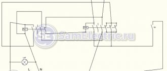
Schematic diagram of the thermostat
Everything is simple here. There is a relay RL1 with a current of 16A for each group that controls the compressor. Key Q1 controls this relay by receiving commands from microcontroller U1. The MK is clocked from quartz at 4 MHz.
There are only two control buttons, these are “PLUS” and “MINUS”, they are connected to the power supply plus and shunted with capacitors C4 and C5, to get rid of contact bounce.
A digital temperature sensor U1 ds18b20 is used, operating using a single-wire protocol.
All indication is on a seven-segment LED indicator with a common anode operating in dynamic mode. The “WORK” LED is a compressor status indicator that shows whether it is on or not.
I took the power from a ready-made pulse generator, at the output of which 12V is removed to the relay and 5V to everything else.
All that remains is to familiarize yourself with the refrigerator circuit and begin developing the compressor control logic.
Electrical diagram of the refrigerator "NORD-214-1". SK - thermostat; EL - incandescent pump; K - start-protection relay; M - compressor; EK1 - electric heater of the cross member; EK2 - electric defrosting heater; SQ - light switch; X - reinforced wire.
As a result, the terminals from the SK thermostat will be disconnected and redirected to the contacts of my relay.
Replacement using the example of the Stinol refrigerator
Thermostat replacement diagram:
- We de-energize the Stinol.
- We remove decorative panels and other elements that interfere with access to the thermostat (often the installation location of the device blocks the lighting unit).
- We remove the block with contacts and regulator. To do this, you will need to unscrew the screws or move the latches.
- Disconnect the terminals with wires that go to the temperature controller.
- Remove the bar securing the gas tube to the chamber wall.
- We remove the broken thermostat from the refrigerator.
- We install the tube of a working thermostat, giving it the required shape and pressing it.
- We connect contacts.
- We adjust the location of the device.
- We install the components and panels in the reverse order.
- Setting up the thermostat.
- Checking the functionality of the refrigerator.
In the process of replacing an old thermostat with a new one, there is a possibility of damage to the device itself and other parts of the unit, so it is advisable to seek help from an experienced technician. If you want to do everything yourself, carefully watch the video instructions.
↑ We are writing a refrigeration program for MK
We begin to think through the logic of the program, but it is quite complex. Even at the beginning of development, after a couple of days of hesitation, I had to erase everything and write the code again, but first having drawn up a flowchart of the logic of the program. Writing a “poem” has become much easier with a flowchart. The general logic of the program is described in the figure below.
Flowchart of the main part of the program
The procedure for polling the button is not specified here, because it occurs constantly at all stages of the program. During periodic polling of the sensor, which is every 3 seconds, the serviceability of the temperature sensor is checked. If communication with the sensor is lost, the program will go into emergency mode when the compressor work/rest timer subroutine is called. To return to normal mode, you will need to correct the connection with the temperature sensor and turn off/on the device.
Block diagram of program operation in emergency mode
This subroutine is a copy of the one that worked on the tray at the beginning of the article, so the previous work was not in vain.
Firmware and sources, as always, are in the footer of the article! As for the fuses, they are all removed, except for CKSEL1, i.e. The microcontroller is configured to operate from an external quartz at 4 MHz.
Temperature regulating device
A thermostat is a fairly simple device. Even in modern refrigerators and refrigerators this is a simple contact group. It is controlled by a pressure gauge with a capillary tube, the end of which is located in the chamber and measures the temperature. Today there are two types of temperature regulators in refrigerators: mechanical and electronic.
A modern thermostat has two main elements. This is a box in which there are control and actuator mechanisms, and a capillary elongated into a tube. The box is a bellows (hermetically sealed tubular spring). The accuracy of the determined indicators depends on its tightness. The compression and expansion of the bellows is controlled by a spring, optimizing it with pressure indicators. Modern mechanical thermostats may have several springs. It depends on the destination: refrigerator or freezer.
An electronic thermostat for a refrigerator is more reliable and allows smooth regulation of the operation of the entire refrigeration system. The price of this device is significantly higher than mechanical ones and ranges between two thousand rubles (while a mechanical one costs up to a thousand). In an electronic thermal relay, a thyristor or sometimes a resistor is responsible for sensitivity.
In refrigerators with high energy consumption, such thermostats quickly fail. In class A+ cooling units with linear compressors, electronic temperature controllers require replacement much less frequently. Therefore, most manufacturers of such equipment are now switching to linear compressors with electronic thermostats.
↑ Design and details of a digital thermostat
It was decided to mount the device on the top lid of the refrigerator. For this purpose, a board was developed consisting of two parts - digital and power.
I cut out windows and holes in the plug. It's good that I had a piece of the front dimming panel from the satellite tuner lying around!
I placed all these pieces of plastic on hot glue. The end result is a pretty nice looking front panel.
I connected the wiring from the board to the contact terminals near the compressor, in accordance with the refrigerator diagram. The photo shows that it’s really time for my refrigerator to retire, but that’s not the point.
Next, I screwed the boards onto the platform from the lid.
The DS18B20 sensor was pulled through the hole on the back wall of the refrigerator, through which the freon tube enters the evaporator inside the chamber. I ran the cable along the box from the thermostat and brought it outside. At the same time, I corrected the problem of the craftsmen with the light bulb, who, as it turned out, put the terminals on the lamp socket crookedly, eh!.. But let’s not talk about sad things.
I ran the system in such a dangerous open state for a couple of days to make sure that everything was working. Then I waterproofed the control board, filled the board with hot glue in the area of the microcontroller and put on the cover.
Repair
The thermocouple (thermistor) cannot be repaired - it is too miniature and has no replaceable parts. The wiring can be repaired (soldered, twisted, replaced), but not the specified elements. The sensor tube for mechanical thermostats is especially not repairable: no matter how well the hole in it is insulated during repair, including solder, sooner or later it will depressurize, and a bellows with flaws is extremely difficult to bring into proper condition - there will always be miscalibration.
The exceptions are the following cases:
- when the contacts come off, there is a break, a short circuit, an incorrect fit - then the connections are resoldered, the parts are positioned properly;
- installing a new thermocouple on an already installed cable (simply cut and solder in place of the old thermistor, without snapping off the wiring chip from the control unit).
A case of repair from user experience
Let's give an example of how the location of a thermistor affects its performance. The case of the Liebherr CP4003 refrigerator is described. In this model, if the temperature sensor malfunctions, an alarm sound is generated, which was observed by the user. The owner ordered a new sensor, but also decided to simultaneously check the old product and try to revive it.
The refrigerator was turned off, defrosted, and the chambers were dried. Then the protective panel (cover) was removed from the detector. In this case, the device type is no frost, and the part in question is placed on a “crying wall”. The detector was dried with a regular hairdryer without removing it from its seat. In this case, it is necessary to ensure that the directed heat is moderate; high temperatures can damage and melt plastic parts. After these procedures, we launched it and everything worked properly.
Obviously, the cause of the problem is an unsuccessful location for installing the temperature sensor. Over time, due to aggressive conditions, the sensor depressurizes, condensation gets inside, which distorts the readings. Accordingly, the system issues an alarm about a breakdown; incorrect messages are sent to the compressor, forcing it to work constantly.
The further solution was that the protective panel was not mounted, the element was left open, without a cover, and condensation was removed from the walls near the device once a week with an ordinary rag or napkin. The new sensor was not needed and was left as a spare.
↑ Results of the work done
In my opinion, everything looks cool and neat.
Mom is very pleased with the invention and is afraid to press the buttons, so as not to break anything without getting used to it. I set the temperature to +4.5° and hysteresis to 1.5°. In total, it turned out that the refrigerator turns on at +6° and turns off at +3°. Based on the time, it turned out that the compressor works for 10 minutes and rests for 55 minutes, which is 0.15 working hours. The Internet says that a work/rest cycle ratio range of 0.2-0.9 is considered normal. I think my figure shows that energy savings are high.
It was an interesting experience in solving this problem that many owners of old refrigerators have.
Add a link to a discussion of the article on the forum
RadioKot >Schemes >Digital devices >Household appliances >
| Article tags: | ThermostatAdd tag |
Refrigerator thermostat
Author: Sobiratel_sxem Published 03/09/2020 Created with the help of KotoEd.
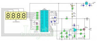
Good afternoon, dear radio amateurs. It's no secret that at the moment there are still quite a lot of refrigerators from older years in operation (for example [12] in our case). One of the problems associated with them is the failure of the thermostat... ...and this breakdown often overtakes the owner unexpectedly... Today we would like to introduce you to a version of the thermostat that we developed about a year ago. So, let's get started. The electrical circuit diagram of the thermostat is shown in the photo below.
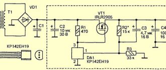
Functionally, the thermostat consists of 4 components: a thermal relay itself, a timer, an output stage and a power source. After supplying the supply voltage, the mains voltage is supplied through a step-down transformer TR1 to a rectifier made on a diode bridge VDS1 [9]. Capacitor C15 is a rectified voltage ripple filter. The power supply stabilizer circuit is made according to the classical circuit of a parametric stabilizer, implemented using zener diodes VD8, VD9 with a current amplifier on transistor VT1. Since the scheme is classic and well known to all radio amateurs, we will not consider in detail the principle of its operation. The output stabilized supply voltage is supplied directly to the power supply circuits of the remaining thermostat components [13,14]. The thermal relay itself is implemented on the DA1 chip using a voltage comparator circuit. The reference voltage of the comparator at the non-inverting input is set by a voltage divider consisting of resistors R4, R5, R6. Resistor R5 is used to set the operating threshold of the comparator. The temperature-sensitive arm of the comparator consists of resistors R8, R9 [1]. When the temperature changes, the resistance of the thermistor R9 changes, and the voltage at the inverting input of the comparator changes accordingly. As soon as the voltage at the inverting input exceeds the value of the reference voltage at the non-inverting input, the output level will be set to a logical level of “0”. And vice versa, when the voltage at the inverting input falls below the reference voltage level, the output level will be set to a logical level of “1”. A chain consisting of resistors R14, R15, diode VD4, capacitor C4 sets the parameters of the comparator hysteresis loop. From the output of the thermal relay, the signal goes to the output of the “AND” logical element (the top one in the circuit), implemented on the DD3 microcircuit. At the same time, through the “Not” element implemented on the DD4 chip, a reset signal is received at the reset input of the timer counter (input R of the DD2 chip) [2,3,4]. The thermostat timer consists of a signal generator made on the DD1 chip and a counter DD2. A chain consisting of resistors R2, R3, capacitor C1 sets the frequency of the generator’s output pulses. From the output of the generator, a sequence of rectangular pulses is supplied to the input of the asynchronous counter DD2. In this case, it acts as a counter-divider [5,6,7]. From the output of the timer, through diodes VD5-VD7, as well as resistors R18-R20, the signal goes to the second input of the “AND” logic element (lower in the circuit), implemented, as described above, on the DD3 chip. From the output of the “AND” element, the signal is supplied to a transistor switch made of transistors VT2, VT3. The load of the transistor switch is the electromagnetic relay K1, the contacts of which switch the electric motor of the refrigerator when the thermostat is operating [8]. A chain consisting of diode VD1 and capacitor C5 is necessary to set counter DD2 to zero when the device is turned on. Diode VD3 and capacitor C8 are necessary to protect the device from possible high-voltage interference that occurs when switching an inductive load in the form of a refrigerator motor, as well as those that occur during operation of the electromagnetic relay K1. These elements must be installed as close as possible to the DA1 chip. Capacitors C11, C12 are needed for the same purposes, but they must be installed as close as possible to the relay K1 itself. A chain consisting of diodes VD10, VD11 is necessary to eliminate high-voltage surges when switching the relay winding K1 with a transistor switch. In this case, the VD10 diode is installed to speed up the operation of the relay during switching [15]. Together with the VD3 diode, capacitors C8, C11, C12, C16, varistor R29, this chain provides good protection of the thermostat from interference that occurs during operation in power circuits. Chain R30, C17 – spark-extinguishing [10]. Chain R21, C10 is necessary to maintain the logical level “1” at the moment of switching counter outputs 1-3. In the absence of this chain, a false operation of the “AND” logical element is possible. Chain R1, HL1 – thermostat supply voltage indicator. Let's briefly consider the operation of a configured thermostat. By default, we will assume that the temperature in the refrigerator is room temperature, i.e. he is completely defrosted. So, after turning on the power, the output of comparator DA1 will be set to the logical level “1” because the temperature of the temperature sensor is higher than the set response threshold. At the same time, thanks to the VD1-C5 chain, the DD2 counter will be reset to zero, after which the timer will begin counting. With the values specified in the diagram and the connection diagram shown, after approximately 8.5 minutes, a logical one level will appear at the timer output. Thus, at both inputs of DD3 the level of logical one will be set and, accordingly, at the output of the “AND” element there will also be a logical “1”. The output signal, through the transistor switch VT2-VT3, as well as the electromagnetic relay K1, will start the electric motor of the refrigerator. A time interval of 6-10 minutes before starting the engine is necessary to protect it from failure during a short-term power outage [11]. Further, the operation of the thermostat can develop according to one of two scenarios: 1. The temperature in the refrigerator compartment will drop below the specified threshold. In this case, the output of the comparator is set to a logical level of “0”. Accordingly, the same level will be established at the upper (according to the circuit) input of the logical element “AND” and its output (chip DD3). Next, the contacts of the electromagnetic relay K1 will open and the engine will turn off. In parallel with this, through the logical element “Not” (DD4), the logical level “1” will go to the reset input of the counter DD2 - the counting of pulses will stop, the counter will be reset to zero. The thermostat will remain in this state until the temperature of the temperature sensor again rises above the set response threshold. After this, the entire work cycle described above will be repeated. 2. The temperature in the refrigerator compartment did not have time to decrease below the set threshold within the specified time. In this case, the timer implemented on the DD1-DD2 microcircuits, with the values specified on the diagram and the specified connection diagram, will count approximately 68 minutes, after which the output of the counter DD2 will be set to the logical level “0”. Accordingly, in this case, similar to the previous one, the electric motor will turn off. After this, the timer will count down the same 8.5 minutes, during which the engine will be turned off and will start it again. This measure is also necessary to protect the electric motor, but in situations where the temperature in the chamber for one reason or another cannot decrease below the set threshold for a long time (for example, the threshold was not set correctly, the refrigerator seals allow warm air inside, the refrigerator was fully loaded with food food at room temperature, etc.). In the absence of such protection, the electric motor can continuously operate for quite a long time, which, in the worst case, can lead to its failure (although modern refrigerators from certain manufacturers are increasingly guilty of this). Setting the thermostat is not difficult. First, you need to disconnect the timer output from DD3, and connect the inputs of the logic element with a jumper. Next, using an additional thermometer as a reference, the thermostat scale is calibrated. To do this, the thermistor R9 is placed in its regular place in the refrigerator chamber and after two or three on-off cycles the temperature at this point is recorded. After this, it is necessary to take measurements at two or three more points and mark them on the scale. The rest of the scale can be easily divided linearly into sections. In this case, a small error can be neglected. If it is necessary to move the temperature control limits up or down, then it is necessary to select the ratio of resistances R4/R6, but the total resistance must remain the same. To expand or narrow the temperature control limits, it is necessary to select the ratio of the resistance of resistor R5 to the resistance of resistors R4/R6. After setting the required temperature control limits, selecting the value of resistors R14/R15 sets the required value of comparator hysteresis. For a household refrigerator, the hysteresis value can be set around 2-4 degrees Celsius. Next, you need to remove the jumper from the inputs of the DD3 chip and connect the timer output back. The total value of the “work/rest” cycle is determined by the frequency of the generator on the DD1 chip, and the relationship between work and rest by the way the DD2 counter is connected. Thus, the setup can be considered complete. The connection diagram for this thermostat instead of the standard one is shown in the diagram below.
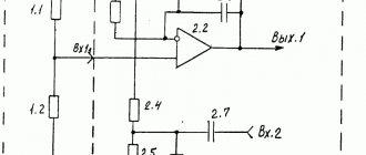
According to the diagram, thermostat terminals X1-X3 are connected to the refrigerator circuit at the indicated points of the same name, and the native thermostat S1 is removed from the circuit. The selection of photos below shows the appearance of the assembled thermostat, as well as the thermostat installed in the refrigerator during testing.
As a modernization of the circuit, it can be proposed to replace the generator on the DD1 chip with an additional frequency divider clocked from the electric lighting network. In this case, the timer operation will be more stable. In addition, when assembling a thermostat on a double-sided printed circuit board using surface-mounted components (SMD, SMD), the size of the finished device can be reduced by at least 2-3 times. Don’t judge strictly - the thermostat was assembled, configured and fully debugged in less than a day because... there was an urgent need for it. The ideal option, of course, is a thermostat on a microcontroller, where, if necessary, you can implement any necessary operating algorithm, connect a display, etc. ...but, as usually happens, at the most inopportune moment something is not at hand... ...and debugging the program would take us much more time than assembling and debugging this thermostat (well, I’m not a programmer, not a programmer, what can we do... )… That’s all for today, with respect, Andrey Savchenko, Maxim Kulakovsky.
List of used literature:
1. TL062CN parameters 2. Logical elements AND, OR, NOT, NAND, NOR and their truth tables 3. CD4081BE parameters 4. K561LN2 parameters 5. NE555 parameters 6. Theory and practice of using timer 555. Part one 7. Parameters K561IE16 8. Parameters of the TRL-12VDC-P-2C relay 9. Parameters of the TP-122-13 transformer 10. Spark arresting circuits 11. Protection of the refrigerator or why the refrigerator cannot be turned on immediately after shutdown 12. Minsk-15M. Operating manual 13. Zener diode. Parametric voltage stabilizers 14. Parametric stabilizers 15. Control of powerful DC load. Part 1
All questions in the Forum.
| What do you think of this article? | Did this device work for you? | |
| 23 | 7 | 12 |
| 0 | 1 |
These articles may also be useful to you:
Radiator thermostat-thermometer-voltmeter-car
Two thermostats.
Thermostat for heated floors.
Thermal controller "Murka"
Automation of temperature conditions in the process of ethyl alcohol production.
K-type thermocouple thermostat
Budget thermostat for a gas boiler.
Two-zone thermal control, “ThermoOpa”. For soft electric heaters.
Thermostat on a PIC16F84 microcontroller and DS18B20 sensor.
A very simple thermostat for heating.
KTY series silicon thermistor thermostat
Simple thermostat with delay on ATTINY13 and DS18B20
GSM thermostat + GSM alarm