When studying electronics, the question arises of how to read electrical diagrams. The natural desire of a novice electronics engineer or radio amateur is to solder some interesting electronic device. However, at the initial stage, sufficient theoretical knowledge and practical skills are, as always, not enough. Therefore, the device is assembled blindly. And it often happens that a soldered device, on which a lot of time, effort and patience was spent, does not work, which only causes disappointment and discourages a novice radio amateur from getting involved in electronics, having never experienced all the delights of this science. Although, as it turns out, the scheme did not work due to a mere trivial mistake. It would take a more experienced radio amateur less than a minute to correct such an error.
This article provides useful recommendations that will help minimize the number of errors. They will help a novice radio amateur assemble various electronic devices that will work the first time.
How to learn to read electrical diagrams
Any radio-electronic equipment consists of individual radio components, soldered (connected) to each other in a certain way. All radio components, their connections and additional symbols are displayed on a special drawing. Such a drawing is called an electrical diagram. Each radio component has its own designation, which is correctly called a conventional graphic designation, abbreviated as UGO. We will return to UGO later in this article.
In principle, two stages can be distinguished in improving the reading of electrical circuits. The first stage is typical for installers of radio-electronic equipment. They simply assemble (solder) devices without delving into the purpose and operating principle of its main components. In fact, this is a boring job, although soldering is good, you still need to learn. Personally, I find it much more interesting to solder something that I fully understand how it works. There are many options for maneuvers. You understand which value, for example a resistor or capacitor, is critical in this case, and which one can be neglected and replaced with another. Which transistor can be replaced with an analogue, and where should a transistor of the specified series be used only. Therefore, I personally prefer the second stage.
The second stage is inherent to developers of electronic equipment. This stage is the most interesting and creative, since one can improve endlessly in the development of electronic circuits.
Entire volumes of books have been written in this area, the most famous of which is “The Art of Circuit Design.” It is to this stage that we will strive to approach. However, this will require deep theoretical knowledge, but it’s all worth it.
We will learn to read electrical diagrams from the simplest examples and gradually move forward.
Power supply designation
Any radio-electronic device is capable of performing its functions only in the presence of electricity. There are fundamentally two types of electricity sources: direct and alternating current. This article deals exclusively with DC sources. These include batteries or galvanic cells, rechargeable batteries, various types of power supplies, etc.
There are thousands of thousands of different batteries, galvanic cells, etc. in the world, which differ in both appearance and design. However, they are all united by a common functional purpose - to supply electronic equipment with direct current. Therefore, in the drawings of electrical circuits, sources are designated uniformly, but still with some minor differences.
It is customary to draw electrical circuits from left to right, that is, the same way as writing text. However, this rule is not always followed, especially by radio amateurs. But, nevertheless, this rule should be adopted and applied in the future.
A galvanic cell or one battery, no matter “finger”, “pinky” or tablet type, is designated as follows: two parallel lines of different lengths. A longer dash indicates the positive pole – plus “+”, and a shorter one – minus “-”.
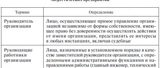
Also, for greater clarity, battery polarity signs may be indicated. The galvanic cell or battery has a standard letter designation G.
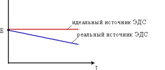
However, radio amateurs do not always adhere to this encryption and often write the letter E instead of G, which indicates that this galvanic element is a source of electromotive force (EMF). The EMF value may also be indicated next to it, for example 1.5 V.
Sometimes, instead of a picture of the power supply, only its terminals are shown.
A group of voltaic cells that can be recharged repeatedly by a battery. In the drawings of electrical circuits they are designated similarly. Only between the parallel lines is a dotted line and the letter designation GB is used. The second letter just means “battery”.
Features of reading circuits
In circuit diagrams, conductors (or tracks) are indicated by lines.
This designates conductors that intersect, but they do not have a common connection and are not electrically connected to each other. And this is what they look like if there is a connection between them. The black dot is a node in the circuit. A node is a connection of several conductors or parts together. They are electrically connected to each other.
Common point
Beginner radio amateurs often have a question: what is this symbol on the diagram?
This is the common point (GND, ground). Previously, it was called the common wire. This is how a single power wire is designated. Usually this is a minus of nutrition. Previously, in the diagrams they could make the common wire and the power plus. In this case, the diagram without a common point would look like this:
A common point with unipolar power supply looks visually better and more compact than if you simply make a single line between them.
It is also called a common point because any other points on the diagrams can be measured relative to it. For example, place the multimeter probe on a common point, and with the second probe you can check any part of the circuit in the diagram.
Why can it be called ground (GND)? Previously, the chassis of the device body could be used as a common wire. This has caused confusion between grounding and earth. It is interpreted in the context of the schema. The circuit that was discussed above - the common point (ground) is simply a minus of the power supply. Another thing is bipolar current sources and grounding.
Bipolar power supply and common point
In a bipolar supply, the common point is the middle contact between plus and minus.
Grounding
An example of grounding would be a filter in computer power supplies.
From the capacitor filter, noise goes to the power supply housing. This is grounding. And from the power supply they must go into the outlet if you have a ground connection, otherwise the body of the power supply itself may be energized. The currents there are not large, they are not life-threatening. This is done to reduce impulse noise in the power supply and safety.
Sometimes in power supplies, instead of the housing, noise from the capacitor goes to a common point. It all depends on the design and circuitry. In this case, there will be more interference than with grounding.
In general, there are different grounding connections on the diagrams. For example, in digital technology, analog ground is separated from digital ground. so as not to disrupt the operating modes of the circuit. Pulse noise can affect the analog part of the circuit.
Designation of wires and their connections on diagrams
Electrical wires perform the function of combining all electronic elements into a single circuit. They act as a “pipeline” - they supply electronic components with electrons. Wires are characterized by many parameters: cross-section, material, insulation, etc. We will deal with installation flexible wires.
On printed circuit boards, conductive paths serve as wires. Regardless of the type of conductor (wire or track), in the drawings of electrical circuits they are designated in the same way - a straight line.
For example, in order to light an incandescent lamp, it is necessary to supply voltage from the battery using connecting wires to the light bulb. Then the circuit will be closed and a current will begin to flow in it, which will cause the filament of the incandescent lamp to heat up until it glows.
The conductor should be denoted by a straight line: horizontal or vertical. According to the standard, wires or live paths can be depicted at an angle of 90 or 135 degrees.
In branched circuits, conductors often intersect. If an electrical connection is not formed, then a dot is not placed at the intersection.
If an electrical connection is formed at the intersection of conductors, then this place is designated by a point called an electrical node. Several conductors can intersect at the same time in a node. Here I advise you to get acquainted with Kirchhoff's first law.
Designations in diagrams
It provides full disclosure of the operation of electrical equipment. The principles of reading circuit diagrams are important for those involved in electrical installation, repairing household appliances, and connecting electrical devices.
Sometimes such situations arise when connections are broken.
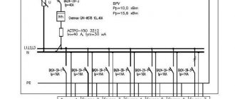
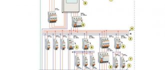
To display insulation pins, single-line and multi-line diagrams are used, the number of lines in which is determined by the number of pins.
Highlight control elements on the electrical circuit diagram, determine which circuits are activated, or disabled, and switched when switching each control node.
Common wire designation
In complex electrical circuits, in order to improve the readability of the diagram, the conductors connected to the negative terminal of the power source are often not shown. And instead of them, signs are used indicating the negative wire, which is also called common or ground or chassis or ground.
Next to the grounding sign, especially in English-language circuits, there is often the inscription GND, short for GRAUND - ground.
However, you should know that the common wire does not have to be negative; it can also be positive. Especially often, the positive common wire was mistaken for the positive common wire in old Soviet circuits, which predominantly used transistors of p–n–p structure.
Therefore, when they say that the potential at some point in the circuit is equal to some voltage, this means that the voltage between the indicated point and the “minus” of the power supply is equal to the corresponding value.
For example, if the voltage at point 1 is 8 V, and at point 2 it is 4 V, then you need to install the positive probe of the voltmeter at the corresponding point, and the negative probe to the common wire or negative terminal.
This approach is quite often used, since it is very convenient from a practical point of view, since it is enough to indicate only one point.
This is especially often used when setting up or adjusting radio-electronic equipment. Therefore, learning to read electrical circuits is much easier by using potentials at specific points.
Electronics for everyone
Ohm's law
| Ohm's law |
| The current in a circuit is proportional to the voltage and inversely proportional to the impedance of the circuit. I = U/R U – voltage value in volts. R is the sum of all resistances in ohms. I is the current flowing through the circuit. |
| Ohm's law in practice |
For example, let's calculate the simplest circuit consisting of three resistances and one source. I will draw the circuit not as is customary in textbooks on TOE, but closer to the real circuit diagram, where they take the point of zero potential - the body, usually equal to the minus of the supply, and the plus is considered a point with a potential equal to the supply voltage. To begin with, we assume that we know the voltage and resistance, which means we need to find the current. Let's add up all the resistances (read the sidebar for the rules for adding resistances) to get the total load and divide the voltage by the resulting result - the current has been found! Now let's see how the voltage is distributed across each resistance. Let's turn Ohm's law inside out and start calculating. U=I*R
since the current in the circuit is the same for all series resistances, it will be constant, but the resistances will be different.
The result was that Usource = U1 +U2 +U3
. Based on this principle, you can, for example, connect 50 light bulbs rated at 4.5 volts in series and easily power them from a 220 volt outlet - not a single light bulb will burn out. What will happen if in this connection, in the middle, you insert one hefty resistance, say one kiloohm, and take the other two smaller ones - one ohm? And from the calculations it will become clear that almost all the voltage will drop across this large resistance.
Kirchhoff's law.
| Kirchhoff's law as an example |
According to this law, the sum of the currents entering and exiting the node is equal to zero, and currents flowing into the node are usually designated with a plus, and currents flowing out with a minus. By analogy with our sewer system, water from one powerful pipe disperses into a bunch of small ones. This rule allows you to calculate the approximate current consumption, which is sometimes simply necessary when calculating circuit diagrams.
Power and losses
The power consumed in a circuit is expressed as the product of voltage and current.
P = U * I
Therefore, the greater the current or voltage, the greater the power.
Because The resistor (or wires) does not perform any useful load, then the power falling out of it is a loss in its pure form. In this case, power can be expressed through Ohm's law as follows: P= R * I2
As you can see, an increase in resistance causes an increase in power spent on losses, and if the current increases, then the losses increase in a quadratic manner. In the resistor, all the power goes into heating. For the same reason, by the way, batteries heat up during operation - they also have internal resistance, on which part of the energy is dissipated. This is why audiophiles use thick copper wires with minimal resistance for their heavy-duty sound systems in order to reduce power losses, since there are considerable currents there.
There is a law of total current in a circuit, although in practice it has never been useful to me, but it doesn’t hurt to know it, so grab some textbook on TOE (theoretical foundations of electrical engineering) from the network, it’s better for secondary schools, everything is described there much simpler and more clearly - without going into higher mathematics.
Part 2. Resistor. Capacitor. Inductance
Conventional graphic designation of radio components
The basis of any electronic device is radio components. These include resistors, LEDs, transistors, capacitors, various microcircuits, etc. To learn how to read electrical circuits, you need to know well the graphic symbols of all radio components.
For example, consider the following drawing. It consists of a battery of galvanic cells GB1, resistor R1 and LED VD1. The conventional graphic designation (UGO) of the resistor looks like a rectangle with two terminals. In the drawings it is designated by the letter R, followed by its serial number, for example R1, R2, R5, etc.
Since an important parameter of a resistor, in addition to resistance, is power dissipation, its value is also indicated in the designation.
The LED UGO has the shape of a triangle with a line at its apex; and two arrows, the tips of which are directed from the triangle. One terminal of the LED is called the anode, and the second is called the cathode.
An LED, like a “regular” diode, passes current in only one direction - from the anode to the cathode. This semiconductor device is designated VD, and its type is indicated in the specification or in the description of the circuit. The characteristics of a particular type of LED are given in reference books or “datasheets”.
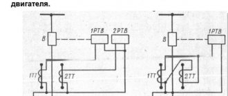
Description of work
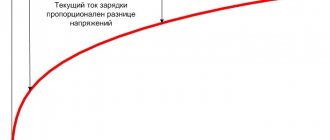
If the electrical circuit is built correctly, then it will work properly. It all works like this. A charge comes from the power source, which enters the conductor and electromagnetic coil of the relay under the terminal block. Through the coil, electric current rushes to the contacts. As soon as the current enters the contacts, the entire network begins to work and the diode turns on. Thanks to the electromotive force, the initial electric current is maintained and reaches its highest values.
Note! It is worth pointing out that without electromotive self-induction, maintaining current in the circuit is impossible, since with a large amplitude, radio elements begin to work poorly. Thanks to this impulse, semiconductor junctions break through and the device is put out of operation. Today, diodes are already built into relays. This allows the electrical circuit to work correctly.
In general, in addition to the topic of how to learn to read electrical circuit diagrams, it is worth noting that they must be read based on training material, which provides information about what certain symbols mean. Only after receiving complete information can you begin to work if the appropriate actions are taken in the electrical wiring.
How to read electrical diagrams for real
Let's return to the simplest circuit, consisting of a battery of galvanic cells GB1, resistor R1 and LED VD1.
As we see, the circuit is closed. Therefore, an electric current I flows in it, which has the same value, since all elements are connected in series. The direction of electric current I is from the positive terminal GB1 through resistor R1, LED VD1 to the negative terminal.
The purpose of all elements is quite clear. The ultimate goal is to light up the LED. However, so that it does not overheat and fail, the resistor limits the amount of current.
The voltage value, according to Kirchhoff’s second law, may differ on all elements and depends on the resistance of resistor R1 and LED VD1.
If you measure the voltage on R1 and VD1 with a voltmeter, and then add the resulting values, their sum will be equal to the voltage on GB1: V1 = V2 + V3.
Let's assemble a real device using this drawing.
We figured out how to read electrical circuits with a minimum set of radio components. Now we can move on to a more complex option.
Adding radio components
Consider the following circuit, consisting of four parallel branches. The first is only a battery GB1, with a voltage of 4.5 V. In the second branch, normally closed contacts K1.1 of the electromagnetic relay K1, resistor R1 and LED VD1 are connected in series. Next in the drawing is the SB1 button.
The third parallel branch consists of an electromagnetic relay K1, shunted in the opposite direction by a diode VD2.
The fourth branch has normally open contacts K1.2 and buzzer BA1.
There are elements here that we have not previously considered in this article: SB1 is a button without a fixed position. While it is pressed, the contacts are closed. But as soon as we stop pressing and remove our finger from the button, the contacts open. Such buttons are also called tact buttons.
The next element is the electromagnetic relay K1. Its operating principle is as follows. When voltage is applied to the coil, its open contacts close and its closed contacts open.
All contacts that correspond to relay K1 are designated K1.1, K1.2, etc. The first digit indicates that they belong to the corresponding relay.
Boozer
The next element, previously unknown to us, is the boozer. The buzzer can to some extent be compared to a small speaker. When an alternating voltage is applied to its terminals, a sound of the corresponding frequency is heard. However, in our circuit there is no alternating voltage. Therefore, we will use an active buzzer, which has a built-in alternating current generator.
Passive buzzer - for alternating current .
Active boozer – for direct current.
The active buzzer has a polarity, so you should adhere to it.
Now we can look at how to read an electrical diagram as a whole.
In the initial state, contacts K1.1 are in the closed position. Therefore, current flows through the circuit from GB1 through K1.1, R1, VD1 and returns again to GB1.
When button SB1 is pressed, its contacts close and a path is created for current to flow through coil K1. When the relay is energized, its normally closed contacts K1.1 open and its normally closed contacts K1.2 close. As a result, the VD1 LED goes out and the BA1 buzzer sounds.
Now let's return to the parameters of the electromagnetic relay K1. The specification or drawing must indicate the series of the relay used, for example HLS‑4078‑DC5V. Such a relay is designed for a nominal operating voltage of 5 V. However, GB1 = 4.5 V, but the relay has a certain operating range, so it will work well at a voltage of 4.5 V.
To select a buzzer, it is often enough to know only its voltage, but sometimes you also need to know the current. You should also not forget about its type - passive or active.
The VD2 diode of the 1N4148 series is designed to protect elements that open the circuit from overvoltage. In this case, you can do without it, since the circuit is opened by the SB1 button. But if it is opened by a transistor or thyristor, then VD2 must be installed.
Ratings of radio components
In general, there are disagreements in this regard. According to GOST at the moment, the nominal values of parts are not indicated on circuit diagrams. This is done in order not to clutter the diagram with information.
The circuit diagram is accompanied by a list of parts, wiring and structural diagrams, as well as a printed circuit board.
There is another generally accepted standard. The diagrams indicate the ratings of some parts and their operating voltages.
For example, in this circuit there are two resistors.
By default, resistance without a prefix is written only as a number. R2 has a resistance of 220 Ohms. And R3 has a letter after the number. The resistance of this resistor reads 2.2k ohms (2,200 ohms).
Consider two capacitors in the diagram.
In this case, C5 is a non-polar capacitor with a capacitance of 0.01 µF. Microfarads can be designated either uF or uF. And capacitor C6 is polar and electrolytic. This is indicated by the plus sign near the UGO. Capacitance C6 is 470 μF. The rated operating voltage is indicated in volts. Here for C6 it is 16 V.
Nanofarads are denoted as nF.
If there is no microfarad (uF) or nanofarad (nF) prefix on the circuit, then the capacitance of this capacitor is measured in picofarads (pF, pF). This condition is not common, so carefully study the diagram you are about to read or assemble. There are few capacitances in farads (F), so µF, nF and pF are used.
Learning to read circuits with transistors
In this drawing we see transistor VT1 and motor M1. To be specific, we will use a 2N2222 type transistor, which operates in electronic key mode.
In order for the transistor to open, you need to apply a positive potential to its base relative to the emitter - for n–p–n type; for the p–n–p type, a negative potential must be applied relative to the emitter.
The SA1 button is fixed, that is, it retains its position after pressing. M1 DC motor.
In the initial state, the circuit is open by contacts SA1. When you press the SA1 button, several paths for current flow are created. The first path is “+” GB1 – contacts SA1 – resistor R1 – base-emitter junction of transistor VT1 – “-” GB1. Under the influence of current flowing through the base-emitter junction, the transistor opens and a second current path is formed - “+” GB1 – SA1 – relay coil K1 – collector-emitter VT1 – “-” GB1.
Having received power, relay K1 closes its open contacts K1.1 in the motor circuit M1. Thus, a third path is created: “+” GB1 – SA1 – K1.1 – M1 – “-” GB1.
Now let's summarize everything. In order to learn to read electrical circuits, at first it is enough just to clearly understand the laws of Kirchhoff, Ohm, electromagnetic induction; methods of connecting resistors, capacitors; You should also know the purpose of all elements. Also, at first, you should assemble those devices for which there are the most detailed descriptions of the purpose of individual components and assemblies.
My course, very useful for beginners, How to Read Electrical Circuits and Create Electronic Devices, will help you understand the general approach to developing electronic devices from drawings, with many practical and visual examples. After completing this course, you will immediately feel that you have moved from a beginner to a new level.