How do dielectrics differ from conductors and semiconductors?
The theoretical difference between these three types of materials can be represented, and I will do so, in the figure below:
The drawing is beautiful, familiar from school, but you can’t really get anything practical out of it. However, this graphic masterpiece clearly defines the difference between a conductor, a semiconductor and a dielectric.
And the difference is in the magnitude of the energy barrier between the valence band and the conduction band.
In conductors, the electrons are in the valence band, but not all of them, since the valence band is the outermost boundary. Exactly, it’s like with migrants. The conduction zone is empty, but welcomes guests, since it has plenty of free work places for them in the form of free energy zones. When exposed to an external electric field, the outermost electrons acquire energy and move to free levels of the conduction band. We also call this movement electric current.
In dielectrics and conductors, everything is similar, except that there is a “fence” - a forbidden zone. This band is located between the valence and conduction bands. The larger this zone, the more energy is required for electrons to overcome this distance. Dielectrics have a larger band size than semiconductors. There is even a condition for this: if dE>3Ev (electronvolt) - then it is a dielectric, otherwise dE
In this article, we will further discuss only dielectrics. And since we’ve gone a little deeper into science, let’s talk further about the properties and quantities that characterize these electrical materials in general.
Dielectrics
Publications based on materials by D. Giancoli. “Physics in two volumes” 1984 Volume 2.
Most capacitors have an insulating material (dielectric), such as paper or plastic film, between the plates. This achieves several goals at once. First, dielectrics resist electrical breakdown better than air, and higher voltages can be applied to the capacitor without charge leaking across the gap between the plates. Secondly, if there is a dielectric spacer, the plates can be placed closer to each other without fear that they may touch. Finally, it was experimentally discovered that when the space between the plates is filled with a dielectric, its capacitance increases by K
times, i.e.
C = KS0
, (25.7)
where C0
is the capacitance corresponding to the vacuum between the plates, and
C
is the capacitance in the case when the space between the plates is filled with a dielectric.
The factor K
is called the relative dielectric constant;
K
values for a number of dielectrics are given in table.
25.1. Please note that for air at a pressure of 1 atm K
= 1.0006, and therefore the capacitance of a capacitor with an air gap differs very little from the capacitance of this capacitor in a vacuum.
For a parallel plate capacitor:
C = K?0 A/d
- [flat capacitor] (25.8),
when the space between the plates is completely filled with a dielectric with dielectric constant K
.
The quantity K?0
appears so often in formulas that the quantity
? = K?0
, (25.9)
which is called the absolute dielectric constant. Then the capacitance of the flat capacitor takes the form
C = ?A/d
Let us recall that ?0
is the electrical constant.
The energy density stored by the electric field E.
Faraday was the first to comprehensively study the influence of the dielectric on the capacitance. He discovered that when the space between the plates of a capacitor is filled with a dielectric, a slightly larger charge accumulates on the plates at the same voltage than when there is air between the plates. In other words, if the charge on each plate of an air-gap capacitor is Q0
, then after introducing the dielectric and connecting the capacitor to the battery with the same voltage
V0
, the charge of each of the plates will increase to
Q = KQ0
[at constant voltage] .
This corresponds to formula (25.7), since after the introduction of the dielectric the capacitance is equal to
C = Q/V0 = KQ0/V0 = KC0
where C0 = Q0/V0
- capacitance in the absence of a dielectric.
Let us now consider a slightly different case (above, when introducing a dielectric, we maintained the voltage constant). Let the plates of a capacitor connected to a battery with voltage V0
, acquire a charge
Q0 = CV0
.
Before introducing the dielectric, we disconnect the capacitor from the battery. After introducing the dielectric (which fills the entire space between the plates), the charge Q0
on each of the plates will not change.
In this case, we will find that the potential difference between the plates will decrease by a K
:
V = V0/K
The capacity will again be equal
Both of these results are consistent with expression (25.7).
The electric field inside the dielectric also changes. In the absence of a dielectric between the plates, the electric field strength between the plates of a flat capacitor is determined by formula (24.3):
E0 = V0/d
,
where V0
is the potential difference between the plates, and
d
is the distance between them.
If the capacitor is insulated, so that the charge on the plates does not change after the introduction of the dielectric, then the potential difference will drop to the value V = V0/K
. The electric field strength in the dielectric will now be equal to
E = V/d = V0/Kd
or
E = E0/K
[in dielectric]. (25.10)
Thus, the electric field strength inside the dielectric is also weakened in K
once. The electric field inside the dielectric (insulator) is weakened, but not to zero, as in the case of a conductor.
What happens in a dielectric can be explained from a molecular point of view. Consider a capacitor whose plates are separated by an air gap. +Q on one plate
, to another charge
-Q
(Fig. 25.7, a).
The capacitor is isolated (not connected to the battery). The potential difference between the plates V0 is determined by expression (25.1): Q = C0V0. (Index 0 corresponds to air between the plates.) Let us now introduce a dielectric between the plates (Fig. 25.7, b). Dielectric molecules can be polar - in other words, they can have a permanent dipole moment while being neutral. A rotational moment will arise in the electric field, which will tend to rotate the dipoles parallel to the field (Fig. 25.7, b); thermal motion prevents the ideal orientation of all molecules, however, the stronger the field, the higher the degree of alignment of the molecules will be. Even if the molecules are not polar, in the electric field between the plates they will experience charge separation, and the molecules will acquire an induced (induced) dipole moment: the electrons, without leaving the molecule, will shift towards the positive plate. Therefore, the picture will always be as shown in Fig. 25.7, b. Ultimately, everything looks as if there was a resulting negative charge on the outer side of the dielectric facing the positive plate, and a positive charge on the opposite side (Fig. 25.7, c). Due to the appearance of this induced charge on the dielectric, some of the electric lines of force will not pass through the dielectric, but will end (or begin) at the charges induced on its surface. Accordingly, the electric field strength inside the dielectric will be less than in air.
You can imagine this picture in a different way (Fig. 25.7, d). The electric field strength inside the dielectric is the vector sum of the field strength E0
, created by “free” charges on the plates, and field strength
Eind
, created by charges induced in the dielectric;
since these fields are directed in opposite directions, the resulting electric field strength inside the dielectric E0 - Ein
will be less than
E0
. The exact relationship is given by formula (25.10):
From considerations of symmetry it is clear that if the dimensions of the plates are large in comparison with the distance between them, the charge induced on the surface of the dielectric does not depend on whether the dielectric fills the entire space between the plates or not, so long as its surfaces are parallel to the plates. Formula (25.10) is also valid in this case, although the equality V = V0/K
no longer true (why?).
The electric field between two parallel plates is related to the surface charge density ?
expression
E = ?/e0
(Section 23.3).
So where ? = Q/A
is the surface charge density on the plate, and
Q
is the total charge of the conductor, often called the free charge (since charges can move freely in the conductor).
Similarly, we will determine the surface density of the induced charge ?
indEind = ?ind/?0
where Eind
— the electric field strength created by the induced charge
Qind = ?inA
on the surface of the dielectric (Fig. 25.7, d);
Qind
is usually called a bound charge (since charges cannot move freely in a dielectric (insulator).
Since, as shown above, Eind = E0(
1 - 1
/ K)
, we get
Since K
greater than 1, the charge induced on the dielectric is always less than the charge on the capacitor plates.
To be continued. Briefly about the following publication:
Gauss's theorem for dielectrics
.
Alternative articles: Electric current, Ohm's Law.
Comments and suggestions are accepted and welcome!
Types and types of dielectrics
The classification of dielectrics is quite extensive. There are liquid, solid and gaseous substances here. They are further divided according to certain characteristics. Below is a conditional classification of dielectrics with examples in list form.
- gaseous
- - polar
- - non-polar (air, SF6 gas)
- - polar (water, ammonia)
- - liquid crystals
- - centrosymmetric
- - amorphous
- - resins, bitumen (epoxy resin)
- - glass
- - disordered polymers
- – irregular crystals
- - ceramics
- - ordered polymers
- - glass-ceramics
- - molecular
- - covalent
- - ionic
- — displacement paraelectrics
- — paraelectrics “order-disorder”
- — single crystals
- - pyroelectrics
- — bias ferroelectrics
- — ferroelectrics “order-disorder”
- — linear pyroelectrics
- - with hydrogen bonds
- - covalent
- - ionic
- - electronic defects
- — ionic defects
- - polar molecules
- — macrodipoles
- — ferroelectric domains
- - crystals in the matrix
If we take liquid and gaseous dielectrics, then the main classification lies in the issue of polarity. The difference is in the symmetry of the molecules. In polar molecules the molecules are asymmetrical, in nonpolar ones they are symmetrical. Asymmetrical molecules are called dipoles. Polar liquids have such high conductivity that they cannot be used as insulating substances. Therefore, non-polar, also transformer oil, is used for these purposes. And the presence of polar impurities, even in hundredths, significantly reduces the breakdown level and negatively affects the insulating properties of non-polar dielectrics.
crystals are a cross between a liquid and a crystal, as the name suggests.
Another popular question about the properties and applications of liquid dielectrics is the following: is water a dielectric or a conductor? Pure distilled water contains no impurities that could cause current to flow. Pure water can be created in laboratory and industrial conditions. These conditions are complex and difficult to meet for an ordinary person. There is an easy way to check whether distilled water conducts current.
Create an electrical circuit (current source - wire - water - wire - light bulb - another wire - current source), in which one of the areas for current flow will be a vessel with distilled water. When the circuit is turned on, the light bulb will not light up - therefore no current flows. Well, if it lights up, it means water with impurities.
Therefore, any water that we encounter: from a tap, in a lake, in a bathroom - will be a conductor due to impurities that create the opportunity for current to flow. Do not swim in a thunderstorm or handle electricity with wet hands. Although pure distilled water is a polar dielectric.
For solid dielectrics, classification mainly lies in the question of activity and passivity or something. If the properties are constant, then the dielectric is used as an insulating material, that is, it is passive. If the properties change depending on external influences (heat, pressure), then this dielectric is used for other purposes. Paper is a dielectric; if water is saturated with water, then current is conducted and it is a conductor; if paper is saturated with transformer oil, then it is a dielectric.
Foil is a thin metal plate; metal is known to be a conductor. For example, there is PVC foil on sale, here the word foil is for clarity, and the word PVC is for understanding the meaning - after all, PVC is a dielectric. Although on Wikipedia, foil is a thin sheet of metal.
Amorphous liquids
- this includes resin, glass, bitumen, and wax. As the temperature rises, this dielectric melts, these are frozen substances - these are wild definitions that characterize only one facet of the truth.
Polycrystals
- these are, as it were, fused crystals united into one crystal. For example, salt.
Monocrystal
- this is a solid crystal, unlike the above-mentioned polycrystal, which has a continuous crystal lattice.
Piezoelectrics
- dielectrics in which, under mechanical action (tension-compression), an ionization process occurs. Used in lighters, detonators, ultrasound examinations.
Pyroelectrics
— when the temperature changes, spontaneous polarization occurs in these dielectrics. It also occurs under mechanical influence, that is, pyroelectrics are also piezoelectrics, but not vice versa. Examples are amber and tourmaline.
Online electrical magazine
The main gaseous dielectrics used in electrical engineering are: air, nitrogen, hydrogen and SF6 gas (sulfur hexafluoride).
Compared to watery and hard dielectrics, gases have low dielectric constants and high resistivity and low electronic strength.
The characteristics of gases in relation to the properties of air (in relative units) are given in the table.
Characteristics of gases in relation to the properties of air
| Trait | Air | Nitrogen | Hydrogen | SF6 gas |
| Density | 1 | 0,97 | 0,07 | 5,19 |
| Thermal conductivity | 1 | 1,08 | 6,69 | 0,7 |
| Specific heat | 1 | 1,05 | 14,4 | 0,59 |
| Electronic strength | 1 | 1 | 0,6 | 2,3 |
Air is used as natural insulation between live parts of electronic machines and power lines. The disadvantage of air is its oxidizing ability due to the presence of oxygen and low electron strength in non-uniform fields. Therefore, air is used occasionally in sealed devices.
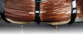
Nitrogen is used as insulation in capacitors, high-voltage cables and power transformers.
Hydrogen has a lower electronic strength compared to nitrogen and is mainly used for cooling electronic machines. Replacing air with hydrogen leads to a significant improvement in cooling, because the thermal conductivity of hydrogen is significantly higher than that of air. In addition, when using hydrogen, power losses due to friction with gas and ventilation are reduced. Therefore, hydrogen cooling allows you to increase both the power and efficiency of an electronic machine.
SF6 gas is most widely used in sealed installations. It is used in gas-filled cables, voltage dividers, capacitors, transformers and high-voltage circuit breakers.
The advantages of a cable filled with SF6 gas are low electronic capacitance, in other words, reduced losses, good cooling, and a comparable conventional design. Such a cable is an iron pipe filled with SF6 gas, in which a conductive core is secured using electrical insulating spacers.
Filling transformers with SF6 gas makes them explosion-proof.
SF6 gas is used in high-voltage switches - SF6 switches - because it has the highest arc-extinguishing properties.