Loss of performance of capacitors may occur due to:
i) short circuit inside it;
b) a break in the chain inside it;
c) increasing leakage current;
d) reducing capacity.
A bad capacitor can be determined using an ohmmeter, a special capacitance measuring device, or a test circuit.
To roughly check the suitability of capacitors, we can recommend checking them using resistance meters (ohmmeter, combined instrument - multimeter).
The verification method is as follows:
1) one of the terminals of the capacitor must be separated (soldered off) from the circuit;
2) the measuring device is configured to measure in the range of tens and hundreds of kilo-ohms or even mega-ohms;
3) multimeter probes are applied to the terminals of the capacitor.
In this case, for high-capacity capacitors from several tens to several thousand microfarads, the initial throw of the instrument needle to “zero” (at the moment of passage of the maximum charge current) will be characteristic, followed by the deviation of the needle to the “infinity” mark;
4) a satisfactory condition of the capacitor dielectric will correspond to an ohmmeter reading of at least 100 kOhm;
5) if there is a break in a high-capacity capacitor (10 - 100 µF), then the arrow of the device is immediately set to the “infinity” mark;
6) for small capacitors, it is almost impossible to determine the presence of a break using an ohmmeter, since the measuring device will show either a short circuit if an insulation breakdown has occurred, or an infinitely large resistance if the capacitor is in good condition or there is a break.
If a break is suspected, such capacitors are usually replaced.
An open circuit inside the capacitor is determined by a measurement circuit consisting of a capacitor, an AC ammeter, and a resistor connected in series to limit the current through the device.
The circuit is connected to an alternating current source, the voltage of which should not exceed 20% of the rated voltage of the capacitor. The absence of current in the circuit indicates an open circuit.
The increase in leakage current is determined by reconnecting the ohmmeter to the terminals of the capacitor.
When connected for the first time, the needle of the device will deflect due to the charging current, and then return to its original position.
If during subsequent connections, repeated at intervals of several seconds, the arrow deviations are repeated, this means that the capacitor has an increased leakage current.
The decrease in capacitance, which occurs most often with electrolytic capacitors, is determined by comparing the nominal capacitance with the actual capacitance, measured using special bridges or circuits and some types of multimeters.
And here read about the intricacies of testing transistors: How to test a transistor.
High Technology News
Principle of operation
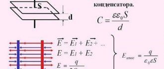
The operating principle on which the operation of this radio element is based is that when used in electrical circuits, it is capable of accumulating an electrical charge.
This property is only possible with alternating electric current - therefore it is used in circuits where it is necessary to separate two current components - direct and alternating. But in circuits with constant electric current, the capacitor will act as a dielectric, since under such conditions it is not able to accumulate charge.
How to choose replacement capacitors
1. You need to take high-quality products with low ESR and inductance. They are more expensive, but they heat up less and explode much less often. In addition, there is the concept of “reactive power of a capacitor” - the power that a capacitor can withstand by passing through itself, and which depends on the loss tangent of the dielectric and the size of the capacitor. That is, the larger the capacitor size, the greater the dissipation and the higher the reactive power.
2. You can place small ceramic capacitors in parallel with the electrolytic capacitors.
3. If voltage surges enter the negative region, then a reverse diode will help, which will prevent the reverse current from “burning” the polar capacitor when reverse voltage is applied.
The lifespan of electrolytic capacitors is limited due to chemical changes in the dielectric and depends on how close the operating voltage is selected to the maximum. In other words, the higher we choose the maximum voltage of the capacitor, the longer it will last.
Resoldering capacitors on the motherboard in our computer center usually costs 1000 rubles, including the work of disassembling and assembling the computer.
Possible faults
A non-working electrical circuit of a device or a non-starting engine itself indicates a malfunction of one or more components of the circuit, but a specific capacitor malfunction may be a consequence of some factors affecting the performance of the element:
- short circuit inside between the plates;
- a break in the internal circuit of the element;
- exceeding the permissible leakage current;
- reducing the nominal capacity of this device;
- physical damage to the housing and violation of its tightness.
Defects and problems of electrolytic capacitors.
Defects and problems of electrolytic capacitors.
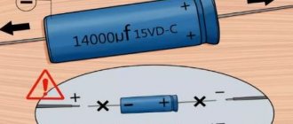
One of the reasons for monitor failure may be failed electrolytic capacitors, which are often used as components of electrical power circuits. Electrolytic capacitors differ from other capacitors in that the aluminum housing contains a liquid (electrolyte) that conducts current when voltage is applied. Almost all electrical power circuits use capacitors in filters. The current after the rectifier is not ideal, ripples are still noticeable. But short voltage drops caused by ripples can be compensated by a capacitor, which acts as a source of additional voltage, stabilizing the supplied voltage. The electrolytes used in capacitors have low internal resistance and must have very good conductivity. To increase the conductivity of the electrolyte (which consists mostly of dispersants), additives must be used. And one of these additives is water. Insufficiently treated water interacts with the aluminum condenser housing, causing corrosion. This creates gases that increase internal pressure - and the condenser begins to swell.
There are special notches on the top plane of the condenser that open when the pressure is too high, allowing gas to escape. Sometimes the notches don't help and the capacitor explodes. The same thing happens when too high a voltage is applied. In addition, the electrolyte that was in the capacitor may leak onto the circuit board and cause a short circuit.
The electrolyte can change its physical state and simply evaporate. Moreover, this can happen not only in a running system, but also when the system is turned off or the monitor board is generally stored separately. Not only components such as memory or processors benefit from good cooling of a computer case. Good cooling also increases the lifespan of capacitors, since the likelihood of evaporation depends on the ambient temperature. A 10°C drop in temperature doubles the lifespan of the capacitor. Usually a defective capacitor can be recognized by the consequences of an explosion. Swelling or even loss of integrity indicates that the capacitor will soon fail (if it is still working). Sometimes the rubber gasket covering the capacitor from the bottom is pushed out by the gas. But capacitors whose electrolyte has evaporated and left no traces on the aluminum case are very difficult to detect. If the capacitor dries out, then its capacitance also decreases. By measuring the capacitance and comparing it with that indicated on the capacitor, you can deal with this problem (a multimeter is usually used to measure the capacitance of the capacitor).
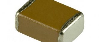
Solid capacitors.
Solid CAP solid capacitors (Fig. 1) provide low series resistance (ESR) as well as a 10-year service life thanks to their aluminum core. These capacitors offer unmatched stability and enable more efficient use of energy, generating less unwanted heat and reducing the potential risk of leakage problems common with older electrolytic capacitors. The use of Solid CAP solid capacitors eliminated the problem of exploding capacitors and provided a tremendous increase in service life.
Rice. 1
Hi-c CAP (Highly-Conductive Polymerized Capacitor) capacitors with a tantalum core are often used in aerospace and military products, a new modification of Hi-c Cap with a different package, improved electrical characteristics (or, for example, polymer aluminum LowESR capacitors with reduced parasitic resistance). Containing the rare metal tantalum at their core, these capacitors not only withstand extremely low and high operating temperatures, but also have a lifespan up to 8 times longer than conventional solid-state capacitors. For overclocking or high workloads, they provide the highest stability and performance.
Other features include high conductivity, support for a self-healing mechanism, and, thanks to their flat shape (Fig. 2), no problems with heat sinks and video cards.
Rice. 2
Hi-c CAP capacitors have excellent electrical characteristics:
— extremely high conductivity due to low ESR; - excellent temperature characteristics that ensure that conductivity is not affected by temperature changes that occur during overclocking, unlike LN2, since previous generation solid-state capacitors are affected by temperature; — a unique self-healing mechanism; — Hi-c CAP capacitors are not only slightly affected by temperature and have high current transfer efficiency, but also have 15 times lower leakage currents; — Hi-c CAP capacitors have an 8 times longer service life compared to conventional solid-state capacitors (even at a constantly elevated temperature of 85ºC they can be used for 16 years); - thanks to their flat shape, they will never create mechanical problems with heat sinks or VGA cards, which conflicts occurred with previous generation solid-state capacitors.
How to identify a breakdown by external signs
A failed electronic component can be identified, or at least its performance can be questioned, thanks to the following external signs:
- violation of the tightness of the housing - in the form of a rupture of the outer housing and protruding electrolyte;
- a swollen element body with visible damage to the geometry (most often they are cylindrical in shape, so bulges on the outer shell indicate its malfunction).
Theory
Very often, when repairing computers and computer equipment - in power supplies, computer motherboards, video cards, monitors, printers and other devices - you can find damaged, swollen capacitors in which electrolyte has leaked, and their housing is destroyed.
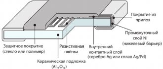
Capacitors are rolls (or stacks) of foil separated by a dielectric. In electrolytic capacitors, one electrode (anode) is the foil, and the other (cathode) is the electrolyte. A thin oxide film deposited on the anode acts as a dielectric. To understand the reason why capacitors fail, let's draw up an approximate equivalent circuit of a capacitor.
How to test a capacitor (starting/high-voltage/film, etc.) with a multimeter
The simplest and most reliable way to check a faulty capacitor is to check it with an ohmmeter, or a specially assembled test circuit. An ohmmeter will show the resistance of an electronic device, by which you can judge the integrity of the dielectric and draw conclusions about the serviceability of the element.
The process itself can be described by an algorithm:
- the measuring device is switched to ohmmeter mode;
- The ohmmeter is set to the upper resistance measurement mode - infinity value;
- the resistance of the device is measured at the terminals - if the device shows a low resistance value (any other than the “infinity” value), then the element under test is unsuitable for further operation; there is a dielectric breakdown or electrolyte leakage inside.
The capacitor saga or “Another blowout”
Sometimes I read Habr, mostly DIY. Sometimes this is rare, because work, you know... And then, not so long ago, I was surprised to come across a habratopic (I won’t point a finger) with a description, so to speak, of repairing an LCD monitor. Having glanced at it quickly, I felt first the desire to cry, and then to laugh. Why? I have to work about 8 hours a day in just one fun organization, one of whose activities is the repair of various equipment, including LCD monitors. I wanted to say everything that could only be said in the comments, but I couldn’t. I decided to write at least to the Sandbox, because I don’t have the strength to remain silent. A quick investigation showed that the author of that same topic dedicated to “repairing” an LCD monitor managed to publish another one, this time about repairing a TV. I must say that these topics generated a not very long thread in a closed section of one well-known technical forum. The general mood of this thread can be characterized by the following quote taken from there:
We are waiting for new opuses from the author on the topic: “How to remove hemorrhoids using crooked hands, a mirror and scissors” “Drill and reducing intracranial pressure”
Often you have to repair equipment after other technicians were unable to identify the problem or were unable to fix it. And very often - after amateurs who tried to “repair” the device using the latest “instructions”, generously scattered throughout the Internet. And, to be honest, I was very surprised to find 2 such “instructions” on Habré at once.
So, let's start with the notorious “repair” of the TV, since this habratopic appeared first. To begin with, I would like to point out the presence of such a parameter as ESR. Anyone can simply google this term and get the entire theoretical basis. Therefore, we will not consider it closely. We are only interested in the fact that the troubleshooting of electrolytic capacitors is carried out not only by the fact of swelling of the aluminum jacket, but also by this very ESR parameter. In fact, this is quite important, since the capacitor swells due to excessive heat, leading to an increase in pressure inside its housing due to evaporation of the electrolyte. And the higher the ESR, the higher the heating of the capacitor. Thus, after thinking for a couple of minutes, we will understand that the power supply may well contain a fairly large number of capacitors, not yet swollen, but already with an increased ESR. Those. essentially already faulty, but not yet visible to the naked eye. To measure ESR, the simplest devices are used, accessible to any child, but many masters use them quite rarely, since the simplest solution to the problem is to replace all electrolytes in the so-called. the “cold” part of the power supply, also called the “secondary”. It is impossible to replace only swollen capacitors without checking the rest, which are not swollen. Because it is not fraught with profit, but with repeated repairs after a short period of time. Moreover, taking into account the circuit design of modern digital technology, it is quite possible that it is not only the power supply unit that is being repaired.
Another mistake the author makes is the soldering technique. For goodness sake, why tin the leads of the capacitors? Which will still have to be cut after installation? What about the use of acid in installation work? Highly active fluxes such as “Soldering acid” are not intended for electrical installation work at all! These are fluxes for soldering ferrous metals. And they are not called acid for nothing. “Soldering acid” can rot the soldering of this same capacitor in a couple of months, even when applied in small quantities. This is why, after using such fluxes, the soldered surfaces must be washed with water, solvents, or better yet, with special liquids. And they should never be used in radio installation work.
Very often, the price lists of service organizations indicate that an increasing factor is applied to the cost of repairing equipment with traces of unqualified repairs, and this is not without reason! As an example, the described TV is already quite capable of delivering an hour or two of fun entertainment to any service after an indefinite period of time. From a week to a year.
The second habratopic, dedicated to “repairing” the monitor, is also very funny. Any specialist knows that repairs begin with measurements. The author of the topic carries out measurements of such parameters as “flammability of a light bulb” - the measurement result is “not lit”, and “monitor performance” - the measurement result is “dead”. The repair method is to just as thoughtlessly replace the visually swollen electrolytes with those torn from the “ancient power supply”, and even with a lower voltage. Of course, LG designers are fools - for some reason they installed capacitors at 16 volts, even if 10-volt ones work... And another miracle - the flammability of the light bulb has risen to “on”, we’ll urgently post it in Habr...
Believe me, all this was written not because I am afraid of being left without a job. On the contrary, such “obstetricians of pregnant women” provide normal craftsmen with work. Unfortunately, often, when after replacing the capacitor the monitor still does not work or does not work satisfactorily, they begin to brutally “dig” the monitor, damaging the tracks on the board, desoldering parts, etc. But repairing such a pile is a completely different matter. For example, we apply an increasing factor of 1.3 to the price for such devices. The problem here is different. Quite recently, I was forced to give a client a “dug” monitor, due to the modest fact that the “digger” “dug” the PSU-inverter board to death, to the point of a hole in the PCB under one of the transistor assemblies. He didn’t know that the wide minus track under the assembly was laid for a reason. And the number of such examples is multiplying, precisely because of the wide distribution of various “instructions” written by various “specialists”...
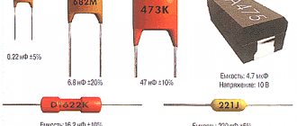
How to find out the capacitance of a capacitor
In most cases, the capacity of the device is indicated in the markings on the element body. However, there is often a need to determine the capacity of electronic components with insufficiently clearly labeled data.
Most multimeters have 5 measurement limits:
- 20 nF (20nF)
- 200 nF (200nF)
- 2 µF (2uF)
- 20 µF (20uF)
- 200 µF (200uF)
This range of measuring the capacitance of elements allows testing both non-polar capacitors and polar, that is, electrolytic. The testing process itself looks like this:
- The control probes of the device are switched to special capacitance measurement sockets (Cx sockets).
The resulting value shows the capacity of the electronic component of the circuit.
In some multimeters, instead of special sockets, metal plates are placed on the working panel. The element is checked by connecting the leads to the platinums while maintaining polarity.
Capacitor ESR measurement
A capacitor (there is such a radio element) is, on the one hand, a simple device that can be made in a jar in the literal sense of the word, but on the other hand, it’s not so simple. This is what the capacitor circuit looks like:
In other words, we have not only capacitance, but resistance. Measuring this resistance is the goal. There are tables to determine the normal operation of the capacitor ESR must be within acceptable limits. Here is one of the tables:
In short, in order to ensure the functionality of the capacitor, when repairing radio equipment (or when using used spare parts), it is necessary to check the capacitance and compliance with the ESR value. I won’t give the whole theory here, but I’ll tell you how to do it.
Now we smoothly move on to practice, namely to device diagrams with which you can test capacitors. And let's do it from simple to complex for the sake of correct logic.
Simple devices can be used to display measurement results as an analogue version (measuring head or ammeter)
And almost the same thing but at 555
There is another option, it allows you to check capacitors without desoldering them from the circuit - the voltage on the probes does not exceed 0.6V
A similar device was once published in the magazine Radio No. 1 in 2011
And devices displaying information using LEDs:
This device was once (and perhaps even now) sold as a kit and as a finished device:
Another option for such a device:
There are devices with sound indication, such as this one:
Initially, the circuit generates an audio tone with a frequency of about 500Hz. When testing capacitors (without soldering them from the circuit), if the ESR is less than 1 ohm (which is considered normal), the generation frequency decreases from 500 to 100 Hz in proportion to the capacitance from 0.1 to 1000 microfarads and then remains silent. If the ESR is greater than 1 ohm, the oscillation frequency begins to increase to (approximately) 5-7 kHz in inverse proportion to the ESR value. Thus, if the generation frequency begins to increase, or remains unchanged, then the capacitor (in most cases) should be replaced.
And finally, you can move on to devices that are built on microprocessors and most often display all the information: both capacity and ESR. Very often these devices are universal, i.e. allow you to check almost the entire range of radio elements from a resistor to a quartz resonator. I will not post diagrams, descriptions and firmware here, if anyone is interested in a more detailed distribution of roles, write in the comments and I will make a detailed review of this or that device. And now I’ll just show you the pictures))
Advertising
Multifunctional watch with Bluetooth, FM radio, LED, mirror Reviews: ***excellent alarm clock***
Advertising
multimeter probes Reviews: ***the wire is soft, the resistance of two wires is 0.07 ohm.***
And finally, the device that I already mentioned in one of my articles
And the body for it:
All these devices are universal and easy to use. Fresh rosin everyone! I will be glad to see your comments)
How to choose replacement capacitors
1. You need to take high-quality products with low ESR and inductance. They are more expensive, but they heat up less and explode much less often. In addition, there is the concept of “reactive power of a capacitor” - the power that a capacitor can withstand by passing through itself, and which depends on the loss tangent of the dielectric and the size of the capacitor. That is, the larger the capacitor size, the greater the dissipation and the higher the reactive power.
2. You can place small ceramic capacitors in parallel with the electrolytic capacitors.
3. If voltage surges enter the negative region, then a reverse diode will help, which will prevent the reverse current from “burning” the polar capacitor when reverse voltage is applied.