Description and purpose of tantalum capacitors
Modern tantalum capacitors are small in size and belong to chip components that are designed for mounting on a board. Otherwise, such parts are called SMD, which stands for “surface mount components.” SMD parts are convenient for automated mounting and soldering processes on printed circuit boards.
The main purpose of electrolytic polarized tantalum capacitors is to act in conjunction with a resistor to process the signal and smooth out its peaks and sharp pulses.
Capacitors are widely used in automotive, industrial, digital, and aerospace applications.
Designation in diagrams
In general, when repairing and re-soldering modern SMD printed circuit boards, it is most convenient when you still have a diagram at hand, looking at which it is much easier to understand what is installed, to find out the location of a certain part, because an SMD capacitor in appearance may not differ at all from the same transistor. The designations of these parts in the circuits remained the same as they were before the arrival of chips on the market, and therefore the capacity and other necessary characteristics can also be easily found by a radio amateur who has not encountered SMD components.
Sources used:
- story/markirovka_kondensatorov_smd_4710038
- https://amperof.ru/teoriya/markirovka-tantalovyx-smd-kondensatorov.html
- https://lampagid.ru/elektrika/komponenty/markirovka-smd-kondensatorov
Design of tantalum solid capacitors
The tantalum capacitor is an electrolytic type. It consists of 4 main parts: anode, dielectric, solid electrolyte, cathode. The manufacture of a tantalum capacitor consists of a number of rather complex technological operations.
Anode manufacturing
The porous granular structure is obtained by pressing from highly purified tantalum powder. During the sintering process under high vacuum conditions at temperatures of +1300...+2000°C, a sponge structure with a developed surface area is formed from the powder. Thanks to it, high capacity is ensured in a small volume. A tantalum capacitor, with the same capacitance as an aluminum device, has a much smaller volume.
Formation of the dielectric layer
A dielectric oxide layer is grown on the surface of a tantalum pentoxide anode through an electrochemical oxidation process. The thickness of the oxide can be adjusted by changing the voltage. Typically, the thickness of the dielectric film is a fraction of a micrometer. The oxide layer has not a crystalline, but an amorphous structure, which has significant electrical resistance.
Obtaining electrolyte
The electrolyte is a solid-state semiconductor - manganese dioxide - which is obtained by heat treatment of manganese salts during the redox process. To do this, the anodic sponge layer is coated with manganese salts, and then heated to obtain manganese dioxide. The process is repeated several times until the anode is completely covered.
Formation of the cathode layer
To improve contact, the electrolyte is coated with a graphite and then a metal layer. The metal usually used is silver. The formed composite is pressed into the compound.
Design features of SMD resistors
The production of a chip resistor is the result of production using film technology. A layer of resistive coating in the form of a film of varying thickness is applied to the substrate. This substrate does:
- ensuring isolation;
- heat removal.
It is also the foundation. The resistance of such a chip directly depends on the material and thickness of the film coating. The complexity of working with thickness has led to two types of chip resistor manufacturing technology:
- Thick Film – thick film (70-10 microns);
- Thin Film – thin film (up to 50 nm).
The former are sometimes called cermet, due to the metal-oxide composition of the powders. Powder in the form of a paste is applied to the base and screen printing is used. After that, burning is carried out in a furnace, bringing the temperature to 9000 C.
The latter are made using ion vacuum deposition of a nickel-nichrome alloy. This achieves resistance accuracy with a tolerance of 0.01% in both directions.
Both types are ultimately adjusted to the specified resistance values using laser trimming (cutting).
It is difficult to distinguish externally what type of resistor it is. Thick Film Chip Resistors technology is somewhat simpler, which is why such elements are cheaper.
SMD resistor device
A passive two-terminal network with a certain resistance has a different shape. There are the following geometric varieties:
- rectangle;
- square;
- oval shape (low profile).
If we talk about the standard size of such circuit components, the JEDEC standard is mainly used. The standard size has a specific code that informs about the dimensions in length H and width W.
Table of sizes of SMD resistors
Features of tantalum capacitors
- The available capacity of these radio components is from 1 to several hundred microfarads
- Relatively low equivalent series resistance (ESR) and lowest leakage. Thanks to these properties, tantalum capacitors work successfully in high-quality audio equipment, test and measurement instruments.
- A thin oxide layer that provides high dielectric constant. The combination of a large surface area of the sponge anode with good dielectric constant provides storage of a large amount of energy.
Unlike electrolytic capacitors, tantalum capacitors explode when overcharged or breakdown. The force of the explosion depends on the size of the capacitor and can damage both adjacent elements and the circuit board.
Video
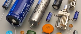
A radio amateur who has encountered the type of SMD capacitor for the first time is perplexed as to how to understand all these “squares” and “barrels” if some do not have markings at all, and if there is one, you won’t understand what it means. But you want to keep up with the times, which means you still have to figure out how to determine the identity of a board element and distinguish one component from another. As it turned out, there are still differences, and the markings, although not always and not on all capacitors, give an idea of the parameters. There are, of course, SMD components without identification marks, but first things first. First you need to understand what this element is and what its task is.
This component works as follows. Each of the two plates located inside is supplied with opposite charges (their polarities differ), which tend to one another according to the laws of physics. But the charge cannot “penetrate” onto the opposite plate due to the fact that there is a dielectric spacer between them, and therefore, not finding a way out and not being able to “escape” from the nearby opposite pole, it accumulates in the capacitor until its capacity is filled.
Content
Breakdowns of tantalum capacitors
When using these effective, but somewhat capricious devices, it is necessary to monitor the occurrence of a failure condition, since they have been known to catch fire when they fail. Failures are due to the fact that, if used incorrectly, tantalum pentoxide changes its amorphous structure to a crystalline one, that is, it turns from a dielectric into a conductor. A change in structures can occur due to too high inrush current. Dielectric breakdown causes an increase in leakage currents, which in turn lead to breakdown of the capacitor itself.
The cause of troubles associated with the operation of tantalum capacitors may be manganese dioxide. The oxygen present in this compound causes the appearance of local fires. Breakdowns with fire are typical for older models. New technologies make it possible to obtain more reliable products.
Breakdowns that occur at high temperatures and voltages can cause an avalanche effect. In this case, the damage often extends over most or all of the device. If the area of crystallized tantalum pentoxide is small, then a self-healing effect often occurs. It is possible due to the transformations occurring in the electrolyte in the event of dielectric breakdown. As a result of all transformations, the crystallized conductor site is surrounded by manganese oxide, which completely neutralizes its conductivity.
Basic information
Understanding the performance characteristics of tantalum and multilayer ceramic capacitors, including reliability of use and response to changes in temperature and voltage, typical test parameters, and how each type of capacitor has been improved, allows you to create capable electronic devices.
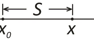
Let's start with the basic concepts. To calculate the capacitance of the capacitor, the formula is used:
C = εR ∙ ε0 ∙ (S/d),
where C is capacity, F; S – overlap area of two plates, m2; εR – relative dielectric constant of the medium; ε0 – dielectric constant of vacuum; d – distance between plates (or dielectric thickness), m.
Other defects of tantalum capacitors
In addition to breakdown, other defects occur in the capacitor as a result of incorrect production technology and violation of transportation and storage rules:
The first type of such defects can appear on the grown dielectric as a result of its sharp impact on a hard surface. The second is during the formation of an electrolyte layer due to the combined action of thermal shock and internal gas pressure in the pores.
If the production technology is violated, foreign substances may appear on the tantalum surface - carbon, iron, calcium, which lead to unevenness of the dielectric layer.
that appeared during the manufacture of the device. Crystallization can occur due to a discrepancy between the electrolyte composition and the technological requirements and incorrect temperature conditions of the process.
Diagnosis of possible faults
The most common malfunction is a breakdown of the dielectric film on the anode. Its thickness is only a few thousand angstroms, which is about 500 times thinner than a human hair.
A small voltage surge can lead to breakdown , in which the dielectric film acquires a crystalline structure and becomes a conductor of electricity. In this case, the capacitor becomes a conductor and the resistance between the anode and cathode approaches zero. On the body, upon breakdown, darkening and sometimes charring of the protective paint coating is often visually noticeable.
It is more difficult to diagnose loss of capacitance rating. It is impossible to identify such a malfunction at home; this requires specialized diagnostic equipment .
The cost of tantalum and niobium capacitors is so low that there is no point in carrying out complex measuring work. The suspicious element is simply replaced with a new one or a known good one.
Tantalum polymer capacitors
Most of the problems characteristic of tantalum capacitors have been solved in tantalum-polymer analogues. Tantalum polymer capacitors use a conductive polymer instead of manganese dioxide as the electrolyte. It gives minimal ESR, which allows much higher currents to pass compared to tantalum predecessors. Tantalum-polymer devices are successfully used as smoothing capacitors in power supplies and voltage converters.
The conductive polymer provides low sensitivity to current pulses, resistance to external factors, lack of structure degradation, and a longer service life. The high stability of capacitance over a wide range of frequencies and temperatures allows the use of tantalum-polymer devices in industrial, telecommunications and automotive electronics and other areas characterized by fluctuations in operating temperatures.
Universal color chart
For a detailed study of this technique, you can consider the domestic GOST 175-72. According to the current rules, each color corresponds to a certain number. Silver and gold represent decimal parts.
Using a universal table, color codes are deciphered
The figure shows an example of a specialized program. With the help of such calculators, determining the denomination is simplified. The calculation is performed automatically. To find out the value in digital form, just make marks in accordance with the color of a specific radio component.
Standard series of denominations
In order to select serial products without errors, it is worth recalling the use of special row designations. For E12, for example, the permitted deviation from the nominal value is no more than 10% upward/downward. Standard values (15; 18; 22 and others) are calculated in such a way as to eliminate errors with maximum error. The difference between adjacent positions must be 200% or more compared to the established tolerance.
Errors for other rows “E” are given in the following list (%):
- 192 (0,5);
- 96 (1);
- 48 (2);
- 24 (5);
- 6 (20).
For your information. Products with a minimum deviation from the nominal value of electrical resistance are marked with three significant rings (numbers). Additional bars indicate a multiplier and a certain tolerance.
Main characteristics of tantalum capacitors
To determine a safe operating mode, it is necessary to calculate the levels of permitted current and voltage values. For calculations, you need to know the following parameters of tantalum capacitors, which are reflected in the documentation:
- Nominal capacity.
These devices have high specific capacitance, which can be thousands of microfarads. - Rated voltage.
Modern models of these devices are mostly designed for voltages up to 75 V. Moreover, for normal operation in an electrical circuit, the part must be used at voltages that are less than the nominal one. Operating tantalum capacitors at voltages up to 50% of the rated voltage reduces the failure rate to 5%. - Impedance (total resistance).
Contains inductive component, parallel resistance, series equivalent resistance (ESR). - Maximum power dissipation.
When AC voltage is applied to a tantalum device, heat is generated. The permissible increase in the temperature of the capacitor due to the released power is established experimentally.
An example of calculating permissible values of currents and voltages
As an example, consider the calculation of the maximum current and voltage values for a capacitor of the 293D series (Vishay): size B, 1 µF ±20%, 35 V. The minimum capacitance value, taking into account an error of 20%, is 0.8 µF.
Let's calculate the values of currents and voltages for two frequency values: 120 Hz and 100 kHz.
Calculation for frequency 120 Hz
The limiting value Vrms can be determined from formulas (3), (4), (5) depending on the level of the DC component of the applied voltage. If a special case is selected with a constant bias equal to half the rated voltage (Vbias = 0.5 Vpp), then you can use Table 6: for capacitors with a rated voltage of 35 V, the Vrms value is 12.37 V.
To determine the value of the maximum rms current, it is necessary to determine the impedance value (formula 10):
Z = 1/2πfC = 1/2π 120 (0.8 10-6) = 1.66 kOhm, (10)
Maximum rms current (formula 6):
Irms = Vrms/Z = 12.37/1660 = 0.007 A
Once again, it is worth recalling that in the calculations the minimum value of the capacitance was used, taking into account the accuracy of the nominal value.
Calculation for frequency 100 kHz
At high frequencies, the main limitation on the amount of current is the permissible power dissipation. The maximum rms current can be calculated using formula (12), knowing the values of Pmax and ESR.
The permissible power dissipation value for type B can be taken from Table 3: Pmax (type B) = 0.085 W.
The ESR value is selected in one of the following ways:
- When determining ESR from the graph (Figure 8). ESR = 1.5 Ohm.
- Using the table value: ESR (+25°C) = 5 Ohm.
The maximum ESR value must be used in calculations. Substituting the found values into formula (12), we obtain:
Irms = √Pmax/ESR = √0.085/5 = 0.13 A
The value of the maximum rms voltage can be determined from formula (3). The impedance value is determined from the graph (Figure 8).
Vrms = Irms Z = 0.13 3 = 0.39 V
In addition to proper calculation of operating conditions, it is necessary to comply with the storage requirements and installation technology of tantalum capacitors.
Features of board design and installation of tantalum capacitors
Almost all printed circuit board materials are suitable for these devices - FR4, FR5, G10, fluoroplastic, aluminum. The shape, size of the seat and installation method are specified by the manufacturers of the parts. The recommended installation parameters can be changed by a specialist who has sufficient knowledge and skills to correctly adjust the soldering temperature.
Before installation, solder paste is applied to the board. Layer thickness – 0.178+/-0.025 mm. In order for the flux contained in the paste to effectively dissolve oxides from the contact points, the optimal soldering temperature regime is selected. This is usually done empirically.
Mounting to the board is done manually or using any type of automated equipment used today. Soldering is done: manually, by wave method, in infrared or convection ovens. Temperature conditions for preheating and soldering are usually provided by manufacturers of specific products.
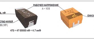
Marking of tantalum capacitors
The markings of capacitors indicate standard parameters: capacitance, rated voltage, polarity. On cases of types B, C, D, E, V, all parameters are displayed, and on case of type A, instead of the voltage rating, its letter code is indicated. The marking may indicate additional information - the manufacturer’s logo, production date code, etc.
Voltage Code Table for Type A Enclosures
Rated voltage
| Code | Rated voltage | Code | |
| 4,0 | G | 20 | D |
| 6,3 | J | 25 | E |
| 10 | A | 35 | V |
| 16 | C | 50 | T |
Types of tantalum capacitor housings and their sizes
Main types and sizes of SMD devices
Housings of components for microelectronics that have the same nominal values may differ from each other in dimensions. Their dimensions are determined primarily by the standard size of each. For example: resistors are designated by standard sizes from “0201” to “2512”. These 4 digits in the SMD component marking indicate a coding that indicates the length and width of the device in inch measurements. In the table provided, typical dimensions are also indicated in mm.
Marking of SMD components - resistors
| Square Chip Resistors and Ceramic Capacitors | |||||
| Standard size | L, mm (inch) | W, mm (inch) | H, mm (inch) | A, mm | W |
| 0201 | 0.6 (0.02) | 0.3 (0.01) | 0.23 (0.01) | 0.13 | 1/20 |
| 0402 | 1.0 (0.04) | 0.5 (0.01) | 0.35 (0.014) | 0.25 | 1/16 |
| 0603 | 1.6 (0.06) | 0.8 (0.03) | 0.45 (0.018) | 0.3 | 1/10 |
| 0805 | 2.0 (0.08) | 1.2 (0.05) | 0.4 (0.018) | 0.4 | 1/8 |
| 1206 | 3.2 (0.12) | 1.6 (0.06) | 0.5 (0.022) | 0.5 | 1/4 |
| 1210 | 5.0 (0.12) | 2.5 (0.10) | 0.55 (0.022) | 0.5 | 1/2 |
| 1218 | 5.0 (0.12) | 2.5 (0.18) | 0.55 (0.022) | 0.5 | 1 |
| 2010 | 5.0 (0.20) | 2.5 (0.10) | 0.55 (0.024) | 0.5 | 3/4 |
| 2512 | 6.35 (0.25) | 3.2 (0.12) | 0.55 (0.024) | 0.5 | 1 |
| Cylindrical chip resistors and diodes | |||||
| Standard size | Ø, mm (inch) | L, mm (inch) | W | ||
| 0102 | 1.1 (0.01) | 2.2 (0.02) | 1/4 | ||
| 0204 | 1.4 (0.02) | 3.6 (0.04) | 1/2 | ||
| 0207 | 2.2 (0.02) | 5.8 (0.07) | 1 |
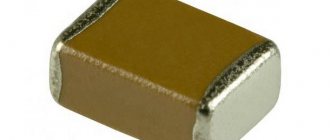
SMD capacitors
Capacitors made of ceramic are the same size as resistors; as for tantalum capacitors, they are determined according to their own standard size scale:
| Tantalum capacitors | |||||
| Standard size | L, mm (inch) | W, mm (inch) | T, mm (inch) | B, mm | A, mm |
| A | 3.2 (0.126) | 1.6 (0.063) | 1.6 (0.063) | 1.2 | 0.8 |
| B | 3.5 (0.138) | 2.8 (0.110) | 1.9 (0.075) | 2.2 | 0.8 |
| C | 6.0 (0.236) | 3.2 (0.126) | 2.5 (0.098) | 2.2 | 1.3 |
| D | 7.3 (0.287) | 4.3 (0.170) | 2.8 (0.110) | 2.4 | 1.3 |
| E | 7.3 (0.287) | 4.3 (0.170) | 4.0 (0.158) | 2.4 | 1.2 |
SMD Inductors and Chokes
Inductive coils can be made in various housing configurations, but their value is also indicated based on the standard sizes. This principle of SMD marking and decoding of codes makes it possible to significantly simplify the installation of elements on the board in automatic mode, and for the radio amateur to navigate more freely.
dr>
Winding components such as coils, transformers and others, which in most cases we make ourselves, may simply not fit on the board. Therefore, such products are also available in compact versions that can be installed on a board.
To determine which coil your project requires, it is best to use the catalog and select the required option according to the standard size there. Typical sizes are determined using a code marking marked with 4 numbers (0805). Where "08" is the length and "05" is the width in inches. The actual dimensions of such an SMD component will be 0.08x0.05 inches.
Diodes and Zener diodes in SMD housing
As for diodes, they are also available in both cylindrical and polyhedron-shaped cases. The typical dimensions of these components are set identically to inductive coils, resistors and capacitors.
| Diodes, Zener diodes, capacitors, resistors | |||||
| Type of shell | L* (mm) | D* (mm) | F* (mm) | S* (mm) | Note |
| DO-213AA (SOD80) | 3.5 | 1.65 | 048 | 0.03 | JEDEC |
| DO-213AB (MELF) | 5.0 | 2.52 | 0.48 | 0.03 | JEDEC |
| DO-213AC | 3.45 | 1.4 | 0.42 | — | JEDEC |
| ERD03LL | 1.6 | 1.0 | 0.2 | 0.05 | PANASONIC |
| ER021L | 2.0 | 1.25 | 0.3 | 0.07 | PANASONIC |
| ERSM | 5.9 | 2.2 | 0.6 | 0.15 | PANASONIC, GOST R1-11 |
| MELF | 5.0 | 2.5 | 0.5 | 0.1 | CENTS |
| SOD80 (miniMELF) | 3.5 | 1.6 | 0.3 | 0.075 | PHILIPS |
| SOD80C | 3.6 | 1.52 | 0.3 | 0.075 | PHILIPS |
| SOD87 | 3.5 | 2.05 | 0.3 | 0.075 | PHILIPS |
Transistors in SMD housing
SMD transistors are made in packages that correspond to their maximum power. The cases of these semiconductor elements can be symbolically divided into two types: SOT and DPAK.
Marking of SMD components
Labeling electronic devices in modern technology already requires professional knowledge, and it’s so simple that it’s hard to understand at first glance, especially for a novice radio amateur. In comparison with parts produced in the Soviet Union, where the marking of the nominal value and type of device was applied in text form, now this is simply a soldering tool meta. There was no need to keep piles of reference literature on hand to determine the purpose and parameters of a particular device.
However, technological processes in industry do not stand still and production automation determines its own rules. It is SMD parts that play the main role in surface mounting, and the robot does not care about marking the parts inserted into the machine; what is placed there, it solders. The marking is needed by the specialist who services this robot.
Download a program to decipher the designation of SMD parts
Features of capacitor storage
Tantalum capacitors are able to maintain performance characteristics for a long time. If the required conditions are observed (temperature up to +40°, relative humidity 60%), the capacitor loses its ability to be soldered during long-term storage, while maintaining other performance characteristics.
General recommendations for extending the service life of a tantalum capacitor and increasing the safety of its operation:
- Compliance with technical process requirements;
- Multi-stage product quality control;
- Compliance with storage conditions;
- Fulfilling the requirements for organizing a workplace for mounting devices on a board;
- Compliance with the recommended soldering temperature conditions;
- Correct selection of safe operating modes;
- Compliance with operating requirements.
Criterias of choice
Capacitor CBB61
In today's market, it can be easy to get confused due to the different types and subtypes of chip capacitors available. They all differ in their characteristics, and each has its pros and cons.
The criteria for selecting specific types of devices are determined by the following factors:
- ability to work at high voltage;
- significant capacity;
- magnitude of breakdown voltage;
- self-inductance;
- stability and long-term work;
- price.
Due to their excellent characteristics, solid tantalum capacitors are very popular in the field of electronic equipment production.