In the previous article we talked about what a capacitor is, and now we will talk about the different types of capacitors. The key factor in distinguishing between different types of capacitors is the dielectric used in their construction. The most common types of capacitors are ceramic, electrolytic (including aluminum, tantalum and niobium capacitors), film, paper and mica.
Each type of capacitor has its own advantages and disadvantages. The characteristics and applications of capacitors may vary. Therefore, the following important factors need to be considered when selecting a capacitor.
- Size : Both the physical size and the size (value) of the container are important.
- Operating voltage : This is an important characteristic of a capacitor. It determines the maximum voltage that can be applied to the capacitor.
- Leakage current : A small amount of current will flow through the dielectric as they are not perfect insulators. This is called leakage current.
- Equivalent series resistance : The capacitor leads have a small resistance (usually less than 0.1 ohms). This resistance becomes a problem when the capacitor is used at high frequencies.
These factors determine how and in what circuits a particular type of capacitor can be used. For example, the voltage rating of an electrolytic capacitor is higher compared to a ceramic capacitor in a similar capacitance range. Therefore they are commonly used in power supply circuits. Likewise, some capacitors have very low leakage current, while others have very high leakage current. Depending on the application, the appropriate capacitor must be selected.
Dielectrics in capacitors
Fixed capacitors are the more common types of capacitors. It is difficult to find an electronic circuit without a capacitor. Most capacitors are named after the dielectric used in the design. Here are the common dielectrics used in capacitor construction:
- Ceramic
- Paper
- Film
- Mica
- Glass
- Aluminum oxide
- Tantalum
- Niobium
The last three are used in electrolytic capacitors. Despite the use of different types of dielectrics in capacitor construction, the functionality of the capacitor remains the same: storing energy in the form of electrical charge between parallel plates.
Capacitor properties
Capacitor Capacitance Meter
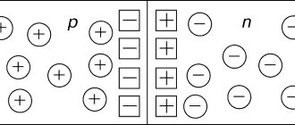
Since the design of the capacitor contains a dielectric, when it is connected to a constant voltage circuit, the current flows only at the first moment of time, when the plates are charging.
In an alternating voltage circuit, cyclic recharging occurs, so the passage of current is observed. Its value is determined by the reactance of the capacitor, which is equal to:
XC=1/(2πfC), where f is the oscillation frequency.
Thus, it becomes clear why at constant voltage there is no current (the frequency is zero and the resistance tends to infinity).
Variable capacitors
Like resistors, capacitors come in fixed and variable types. Variable capacitors are capacitors whose capacitance can be changed mechanically or electronically. Such capacitors are commonly used in resonant circuits (LC circuits) for radio and impedance matching in antennas. These capacitors are usually called tuning capacitors.
There is another type of variable capacitor called a trimmer capacitor . They are mounted on printed circuit boards and are used to calibrate equipment. These are very small non-polarized capacitors. They are generally not available for regular customer use. The capacitance of variable capacitors is very small, usually on the order of a few picofarads (typically less than 500 pF).
Mechanical variable capacitors consist of a set of semicircular metal plates mounted on the rotor axis. The rotor is placed between the metal stator plates. The overall capacitance value (C) for this type of capacitor is determined according to the position of the moving metal plates in relation to the stationary metal plates. When the axis rotates, the overlap area between the stator plates and the rotor plates will change, and so will the capacitance accordingly.
When two sets of metal plates are completely connected together, the capacitance value is usually at its maximum value. High voltage trimmer capacitors have large air gaps or spaces between the plates with relatively large breakdown voltages on the order of kilovolts.
Mechanical variable capacitors usually use air or foil plastic as the dielectric. Today, the use of vacuum variable capacitors is increasing as they provide better operating voltage range and higher current carrying capacity. The capacitance of mechanically adjusted capacitors can be changed using a screw on the top of the capacitor.
In the case of electronically controlled variable capacitors, a reverse-biased diode , in which the thickness of the depletion layer will vary depending on the applied DC voltage. Such diodes are called variable capacitance diodes or simply varicaps or varactors.
Classification
The main parameters of capacitor products are determined by the type of dielectric. The stability of the capacitance, the dielectric loss tangent, the piezoelectric effect and others depend on the material. Based on this, it is advisable to classify models according to the type of dielectric.
Based on this feature, the following types of products are distinguished:
- vacuum;
- with air dielectric;
- radioelements in which the dielectric is liquid;
- with a solid inorganic dielectric (glass, mica, ceramics). Characterized by low leakage current;
- models with paper dielectric and combined, paper-film;
- DC oil capacitors;
- electrolytic;
- category of oxide capacitors, which include oxide semiconductor and tantalum capacitors;
- solid-state, in which an organic polymer or polymerized semiconductor is used instead of a liquid electrolyte.
In solid-state models, the service life is longer than that of liquid electrolytic models and is about 50,000 hours. They have less internal resistance, that is, the ESR is almost independent of temperature, they do not explode.
Products are also classified according to another important parameter - change in capacity. Based on this feature they distinguish:
- permanent capacitors, that is, those that have a constant capacitance;
- variables in which the change in capacitance can be controlled mechanically or using applied voltage (varicaps and variconds), as well as by changing temperature (thermal capacitors);
- a class of tuning capacitors that are used to adjust or equalize working capacitances when setting up circuits, as well as for the purpose of periodically adjusting various circuits.
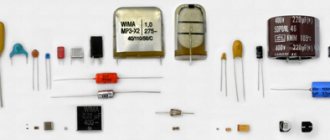
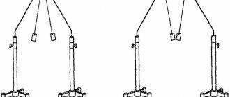
All existing capacitors can be divided into general and special. General purpose products include the most common low-voltage capacitors (see Fig. 6). There are no special requirements for them.
Rice. 6. General purpose capacitors
All other capacitive radioelements belong to the special purpose class:
- pulse;
- launchers;
- high voltage (see Fig. 7);
- interference suppression
- dosimetric, etc.;
Rice.
7. High-voltage capacitors The devices shown in the photo can operate in high-voltage circuits of relatively low frequency.
Ceramic capacitors
Ceramic capacitors are the most commonly used capacitors in the electronics industry. They are also the most produced capacitors, with over 1000 billion units produced annually. The name comes from the ceramic material, which is the dielectric, used in its construction.
Ceramic capacitors are fixed capacitance capacitors and are typically very small (both in physical size and capacitance). The capacitance of ceramic capacitors typically ranges from picofarads to several microfarads (less than 10 µF). These are non-polarized capacitors, so they can be used in both DC and AC circuits.
The design of capacitors of this type is very simple. The small ceramic disc is coated with silver on both sides. Therefore they are also called disk capacitors. The ceramic acts as a dielectric (insulator) and the silver coating forms the electrodes.
Read also: Piezo igniter
The thickness and composition of the ceramic layer will determine the electrical properties of the capacitor . To achieve high capacitance values, several layers of such a disk are stacked on top of each other to form a multilayer ceramic chip capacitor (MLCC). Modern electronics usually consist of such MLCC capacitors.
The capacitance of ceramic capacitors is large compared to their size. Ceramic capacitors are divided into two classes depending on the application.
Class 1 ceramic capacitors
Such capacitors are often used in resonant circuits due to their high stability and low losses. The most common type of ceramic used in Class 1 capacitors is made from titanium dioxide (TiO2) with a small amount of zinc and magnesium added as additional compounds. They are added to achieve the highest possible linear performance.
Class 1 capacitors have low dielectric constant and therefore relatively low volumetric efficiency. Therefore, the capacitance range of Class 1 capacitors is small. The electrical losses of Class 1 capacitors are very low, and the dissipation factor is 0.15 percent. The capacitance value does not depend on the applied voltage.
Such capacitors have a liner temperature coefficient. All of these characteristics of Class 1 ceramic capacitors make them useful in circuits such as high-Q filters and oscillator circuits such as PLLs. Class 1 ceramic capacitors are not afraid of aging.
Class 2 ceramic capacitors
Such capacitors are often used in buffers, communication circuits, and bypass systems due to their high efficiency in terms of volume. This high volumetric efficiency is due to their high dielectric constant. The capacitance of class 2 capacitors depends on the applied voltage and has a non-linear change over different temperature ranges.
Accuracy and stability are lower compared to Class 1 ceramic capacitors. The ceramic dielectric for Class 2 capacitors is made of ferroelectric materials such as barium titanate (BaTiO-3-), aluminum or magnesium silicates, and alumina.
Due to the high dielectric constant of Class 2 capacitors, high capacitance values are possible in a smaller size than Class 1 capacitors with the same voltage rating. Hence, they are used in buffers, filters and communication circuits where a capacitor is required to maintain minimum capacitance. Class 2 capacitors can age over time.
Another class of ceramic capacitors, called Class 3, is also available, with higher dielectric constant and better volumetric efficiency. But the electrical performance of this class is worse, as well as low accuracy and stability.
Generally, ceramic capacitors have lower ESR (equivalent series resistance) and leakage current compared to electrolytic capacitors. The operating voltage of class 1 ceramic capacitors is up to 1000 V, class 2 ceramic capacitors are up to 2000 V.
The main advantage of ceramic capacitors is that there are no coils inside their design, which means there is no inductive factor during operation of the circuit. Therefore, ceramic capacitors are suitable for high frequency applications.
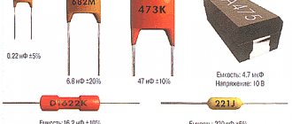
Ceramic capacitors are available in conventional two-terminal through-hole designs, multilayer surface mount (SMT) mode, and specialty lead-free disk capacitors that are designed specifically for PCB applications. Both through-hole and surface-mounted ceramic capacitors are often used. Ceramic capacitors typically have a 3-digit number coded on their case to identify the capacitance value, usually in picofarads (pF).
In this case, the first two digits are used to indicate the capacity, and the third digit indicates the number of zeros added. For example, a ceramic capacitor labeled 153 would read 15 and 3 zeros in picofarads, which is equivalent to 15,000 pF or 15 nF.
Parasitic parameters
Certain types of parameters are parasitic, which they try to reduce during design and manufacturing. Their description is given below.
Equivalent circuit
Electrical insulation resistance of the capacitor dielectric, surface leakage Rd and self-discharge
This parameter depends on the properties of the dielectric and the housing material. It shows how much the charge decreases over time for an element not included in an external circuit. Leakage occurs as a result of imperfection of the dielectric and along its surface.
For some capacitors, the characteristics indicate a time constant T, which shows the time during which the voltage on the plates will decrease by e (2.71) times. Numerically, the time constant is equal to the product of leakage resistance and capacitance.
Equivalent series resistance (Rs)
The equivalent series resistance of the ESR (in English literature ERS) is composed of the resistance of the material of the plates and leads. Surface dielectric leakage may also be added to this.
At its core, EPS is a resistance connected in series with an ideal capacitor. Such a circuit in some cases can affect the phase-frequency characteristics. ESR must be taken into account when designing switching power supplies and autoregulation circuits.
Electrolytic capacitors have a feature where, due to the presence of electrolyte vapor inside, affecting the terminals, the ESR value increases over time.
Equivalent series inductance (Li)
Since the terminals of the plates and the plates themselves are metal, they have some inductance. Thus, the capacitor is a resonant circuit, which can affect the operation of the circuit in a certain frequency range. SMD components have the lowest inductance due to their lack of wire leads.
Dielectric loss tangent
The ratio of active power transmitted through a capacitor to reactive power is called the dielectric loss tangent. This value depends on the losses in the dielectric and causes a phase shift between the voltage on the plate and the current. Loss tangent is important when operating at high frequencies.
Temperature coefficient of capacity (TKE)
TKE means the change in capacitance with temperature fluctuations. TKE can be either positive or negative, depending on how the capacitance behaves with temperature changes.
For filtering and resonant circuits, to compensate for temperature drift in one circuit, elements with different TKE are used, so many manufacturers group the elements produced by the value and sign of the coefficient.
Dielectric absorption
This effect is also called the memory effect. It manifests itself in the fact that when a capacitor is discharged through a low-resistance load, after some time a small voltage appears on the plates.
The amount of dielectric absorption depends on the materials from which the element is made. It is minimal for Teflon and polystyrene and maximum for tantalum capacitors. It is important to consider the effect when working with precision devices, especially integrating and differentiating circuits.
Parasitic piezoelectric effect
The so-called “microphone effect” is expressed in the fact that when exposed to mechanical loads, including acoustic vibrations, the ceramic dielectric in some types of devices exhibits piezoelectric properties and begins to generate interference.
Self-healing
Electrolytic paper and film capacitors have the property of self-healing after electrical breakdown. These types of capacitors and their varieties have found application in circuits that provide starting of electric motors, especially if a three-phase asynchronous electric motor is connected to a single-phase network. The recovery property is widely used in strength engineering.
Film capacitor
Film capacitors are the most commonly used type of capacitor among all other types which have differences in their dielectric properties. Film capacitors are capacitors with an insulating plastic film as the dielectric and are non-polarized capacitors.
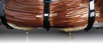
The dielectric materials for these capacitors are made in the form of a thin layer equipped with metal electrodes and wound on a cylindrical winding. Both electrodes of film capacitors can be made of zinc or metallized aluminum.
The main advantage of a film capacitor is the direct connection of its internal structure to the electrodes at both ends of the winding. This direct contact with the electrodes results in a reduction in the length of all current paths. This design behaves like a large number of individual capacitors connected in parallel. In addition, the design of this type of capacitor provides low ohmic losses and low parasitic inductances. These film capacitors are used in AC power supplies as well as high frequency applications.
Read also: Different types of amplifiers and their applications
Some examples of films that are used as dielectric for film capacitors are polypropylene, polyethylene naphthalate, polyester, polyphenylene sulfide and polytetrafluoroethylene. Film-type capacitors with a capacitance range from 5 pF to 100 µF are available for sale Film capacitors are also available in various forms, including:
- Wrap & Fill Type (Oval and Round): In this type, the ends of the capacitor are sealed with epoxy resin and the capacitor is wrapped with thick plastic tape.
- Epoxy Case (Rectangular and Round): This type of capacitors are encased in a molded plastic case filled with epoxy resin.
- Metal Case (Rectangular and Round): These types of capacitors are encased in a metal tube or metal can and sealed with epoxy resin.
Currently, capacitors with the above package are available with both radial and axial leads. The main advantage of film capacitors is that they perform well at high temperatures compared to paper capacitors.
These capacitors offer close tolerance, high reliability, and a very long service life. Examples of film type capacitors are: axial lead cylindrical film capacitor, rectangular film capacitor and foil film capacitors. They are given below:
- Axial output type:
- Radial lead type:
These film capacitors require much thicker dielectric material to avoid breakdown and breaks in the dielectric film. Therefore, they are suitable for circuits requiring low capacitance values.
Connection of capacitors
There are two connection methods: parallel and serial. With a parallel connection, the total capacitance is equal to the sum of the capacitances of the individual elements: C total. = С 1 + С 2 + … + С n .
For a series connection, the capacitance calculation is calculated using the formula: Ctot. = ( C1* C2 *…* Cm ) / ( C1 + C2+…+Cn )
To quickly calculate the total capacitance of connected capacitors, it is better to use our calculators:
- https://www.asutpp.ru/kalkulyator-rascheta-posledovatelnogo-soedineniya-kondensatorov.html
- https://www.asutpp.ru/kalkulyator-rascheta-parallelnogo-soedineniya-kondensatorov.html
Film power capacitors
The design technologies and materials that are used for large power film capacitors are generally similar to those for conventional film capacitors. However, these high power rating capacitors are used in power systems and electrical installations.
Power film capacitors are used in a variety of devices. These capacitors serve as snubber capacitors when a resistor is connected to them in series. They are also used in close-tuned or low-tuned filter circuits to filter out harmonics, and as surge capacitors.
Operating principle of a capacitor
Design
In the diagrams, the capacitor is indicated as two parallel lines that are not interconnected:
This corresponds to its simplest design - two plates (plates) separated by a dielectric. The actual design of this product most often consists of plates wrapped in a roll with a layer of dielectric or other fancy shapes, but the essence remains the same.
Capacitor capacity
Electrical capacity is the ability of a conductor to accumulate electrical charges. The more charge a conductor can hold at a given potential difference, the greater the capacitance. The relationship between charge Q and potential φ is expressed by the formula:
C=Q/φ
where Q is the charge in coulombs (C), φ is the potential in volts (V).
Capacitance is measured in farads (F), which you remember from physics lessons. In practice, smaller units are more common: millifarad (mF), microfarad (µF), nanofarad (nF), picofarad (pF).
The storage capacity depends on the geometric parameters of the conductor and the dielectric constant of the medium where it is located. So, for a sphere made of conductive material it will be expressed by the formula:
C=4πεε0R
where ε0—8.854·10^−12 F/m, the electrical constant, and ε is the dielectric constant of the medium (tabulated value for each substance).
In real life, we often have to deal not with one conductor, but with systems of such. So, in a regular flat capacitor, the capacitance will be directly proportional to the area of the plates and inversely to the distance between them:
C=εε0S/d
ε here is the dielectric constant of the spacer between the plates.
Capacity of parallel and serial systems
A parallel connection of capacitors represents one large capacitor with the same dielectric layer and the total area of the plates, so the total capacitance of the system is the sum of those of each of the elements. The voltage in a parallel connection will be the same, and the charge will be distributed between the circuit elements.
C=C1+C2+C3
A series connection of capacitors is characterized by a common charge and distributed voltage between the elements. Therefore, it is not the capacity that is summed up, but its inverse:
1/C=1/С1+1/С2+1/С3
From the formula for the capacitance of a single capacitor, it can be concluded that with identical elements connected in series, they can be represented as one large one with the same plate area, but with the total thickness of the dielectric.
Polypropylene capacitor
A polypropylene capacitor is one of many types of film-type capacitors. Polypropylene capacitors are capacitors that have polypropylene film as a dielectric. Polypropylene capacitors are available in a range of capacitances from 100 pF to 10 µF.
The main feature of a polypropylene capacitor is its high operating voltage, up to 3000 V. This feature makes polypropylene (pp) capacitors useful in circuits where the operating voltage is typically very high, such as power amplifiers, especially valve amplifiers, power supply circuits, and television circuits.
Polypropylene capacitors are also used in communication and storage applications due to their high insulation resistance values. They also have stable capacitance values for frequencies below 100 kHz. These polypropylene capacitors are used in applications that require noise suppression, communication, time filtering, blocking, bypass, and pulse processing tasks.
Main settings
The main parameters of capacitors that are used in the design and repair of radio electronics devices are capacitance and rated voltage. In addition, there are several additional parameters that can affect the elements of the circuit. Capacitors have the following main characteristics.
Capacity
This is the most basic parameter that characterizes the accumulation of electrical charge. The value is calculated using various formulas, depending on the design features: flat, cylindrical or round capacitor. In practice, most of them are produced as flat varieties. The capacity of modern devices varies from units of picofarads to tens of thousands of microfarads and even units of farads.
Specific capacity
This relative parameter relates the dimensions to the size of the container. Thus, the higher the specific capacitance, the smaller the dimensions of the structure, however, the electrical strength (operating voltage) may decrease.
Energy Density
This parameter is important when using capacitors as energy storage devices; it determines the amount of energy per unit mass or volume of the element.
Rated voltage
The voltage value at which operating parameters are maintained during the service life is called nominal. The operating voltage must be less than the rated voltage.
Important! Exceeding the rated voltage may result in failure of the element. The electrolytic capacitor may explode in this case.
Contrary to popular belief, an element connected to a circuit with a voltage several times less than the nominal voltage retains all other parameters.
Polarity
These types of capacitors, such as electrolytic ones, often require inclusion in a circuit with respect to polarity. Since such elements are used mainly as storage devices or filters, this is not a problem. Failure to comply with polarity leads to:
- capacity mismatch;
- damage.
The marking must contain information about the polarity of the connection.
Risk of destruction (explosion)
Explosive destruction is typical for electrolytic capacitors. The cause of the explosion is heating, which occurs due to:
- non-compliance with polarity;
- location near heat sources;
- aging (increased leakage and increased equivalent resistance).
To reduce the consequences of destruction, a safety valve is installed at the end of the body or notches are formed on the lid. This design ensures that with a sharp increase in pressure inside the housing, accumulated gases and electrolyte are released through a valve or a cap broken along the notches. This prevents an explosion, in which the plates and electrolyte are scattered over a large area and cause short-circuiting of the board elements. Cooling the device reduces the likelihood of destruction.
Consequences of destruction
Polycarbonate capacitor
Polycarbonate capacitors are capacitors that use polycarbonate as a dielectric. These types of capacitors are available in capacitance ranges from 100 pF to 10 µF and have operating voltages up to 400 VDC. These polycarbonate capacitors can operate in a temperature range from -55°C to +125°C without derating.
These capacitors are not used in high precision applications due to their high tolerance levels of 5% to 10%. Polycarbonate capacitors are also used for alternating current. Sometimes they are also found in switching power supplies.
How to check a capacitor
Sometimes a malfunction of an electrolytic capacitor is detected without checking - by swelling or rupture of the top cover. It is deliberately weakened by a cross-shaped notch and acts as a safety valve, bursting at low pressure. Without this, the gases released from the electrolyte would rupture the capacitor body with spraying of the entire contents. But violations may not appear outwardly. Here's what they are: Due to chemical changes, the capacity of the element has decreased. For example, capacitors with liquid electrolyte dry out, especially at high temperatures. Because of this feature, there are operating temperature restrictions for them (the permissible range is indicated on the case). An output break has occurred.
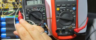
Test of electrolytic capacitors.
Conductivity has appeared between the plates (breakdown). Actually, it exists and is in good condition - this is the so-called leakage current. But during a breakdown, this value turns from tiny to significant. The maximum permissible voltage has decreased (reversible breakdown). For each capacitor there is a critical voltage that causes a short circuit between the plates. It is indicated on the body.
It will be interesting➡ How are capacitors indicated on the diagram?
If this parameter is reduced, the element behaves during testing as if it were working, because the testers supply a low voltage, but in the circuit it behaves as if it was broken. The most primitive way to test a capacitor is for a spark. The cell is charged, then the terminals are short-circuited with a metal tool with an insulated handle.
It is advisable to wear rubber gloves on your hands. A serviceable element discharges with the formation of a spark and a characteristic crackling sound, while a non-working element discharges sluggishly and imperceptibly. This method has two disadvantages:
- danger of electrical injury;
- uncertainty:
Even in the presence of a spark, it is impossible to understand whether the actual capacity of the radio component matches the nominal one. A check using a tester is more informative. It is best to use a special LC meter. It is designed to measure capacity, and is designed for a wide range. But a regular multimeter will tell you a lot about the condition of the capacitor.
Mica capacitors with silver plates
Silver plated mica capacitors are capacitors that are made by depositing a thin layer of silver on mica material as a dielectric. The reason for using such mica capacitors is because of their high performance compared to any other types of capacitors.
Silver plated mica capacitors This is much better than any other type of capacitor available commercially today. The temperature coefficient of these capacitors is much better than other types of capacitors.
And this value is positive, and usually ranges from 35 to 75 ppm/C, with an average value of +50 ppm/C. values for mica capacitors typically range from a few picofarads to 3300 picofarads. Mica capacitors with silver plates have a very high quality factor and low power factor. These capacitors have a voltage range from 100V to 1000V.
Read also: Rectifier diodes and LEDs
Mica capacitors with silver plates are used in RF generators. They are not used in communication devices due to their high cost. Due to their size and cost, they are currently little used.
Classification and main characteristics of capacitors
Air condensers in small refrigeration machines can be classified as follows.
According to the method of circulation of cooling air, condensers are distinguished with natural circulation (free movement) and with forced air movement.
According to the conditions of movement of the refrigerant in the sections of the apparatus, condensers are divided into the following types: with serial, parallel and series-parallel movement.
Based on their installation location, condensers are classified into built-in (installed directly on the unit frame next to the compressor) and remote (installed separately from the compressor, usually outside the building, on the side or on the roof of the engine room).
Depending on the type of heat transfer surfaces, condensers can be smooth-tube, fin-tube, sheet-tube and panel.
Appliances with natural circulation (convection) of air are used mainly in household refrigerators. Such a device has a single-section design with sequential movement of the refrigerant. The most widespread are two types of construction: sheet-tube (which is a flat coil made of a round tube, usually with a diameter of 6 mm, tightly pressed to a metal sheet having perforations of various types) and ribbed-tube (which is a flat tubular coil, similar to the previous design, but with on the outside there are fins made of pieces of thick wire with a diameter of 1.5-2 mm, welded to the tubes along the height of the entire coil).
In some cases, the condenser of a domestic refrigerator may have a panel design, where, as in the evaporator, the refrigerant passes through channels inside a two-layer sheet.
Devices with forced air movement are mainly made using finned tubes by attaching plate fins to smooth pipes. The latter can take different forms (this issue will be discussed in detail below). Such devices are also called plate-ribbed. Such devices have become widespread due to the relatively low labor intensity of their manufacture.
Finning can also be done by winding tape onto a pipe or by extruding fins directly from the pipe material. Sometimes fins are made not only externally, but also internally by using various inserts-nozzles on the refrigerant side. As will be shown below, such devices (having double-sided fins) have a high heat transfer capacity, but due to technological difficulties in manufacturing, they have not yet found widespread use in domestic and world practice.
The air condenser of a small refrigeration machine is one of the structural units (elements) of a refrigeration unit, therefore its characteristics and ways of improving them are closely related to the development and improvement of other elements: compressor, receiver, frame, etc.
In order to determine the main modern trends in design and assess the possibility of predicting the characteristics of small refrigeration units, the authors analyzed the characteristics of units produced by ten leading companies in nine industrialized countries of the world. Medium and low temperature units with cooling capacity from 200 to 6000 W are considered. The following main characteristics were analyzed: refrigeration coefficient e; specific material consumption M; specific occupied volume V; corrected sound power level U.
Electrolytic capacitors
Electrolytic capacitors are typically used where very large capacitance values are required. Electrolytic capacitors have a metal anode covered with an oxidized layer, usually used as its dielectric. The other electrode of the capacitor is a non-solid or solid electrolyte.
Most electrolytic capacitors are polarized. These capacitors are classified according to their dielectric material. They are mainly divided into three classes:
- Aluminum electrolytic capacitors - Aluminum acts as a dielectric.
- Tantalum Electrolytic Capacitors - Tantalum oxide acts as its dielectric.
- Niobium Electrolytic Capacitors - Niobium oxide acts as its dielectric.
Typically, the dielectric constant of tantalum oxide is almost three times the dielectric constant of aluminum dioxide, but this dielectric constant only determines the dimensions. Three types of electrolytes are commonly used:
- Not solid (liquid): these capacitors have a conductivity of about 10 ms/cm, and cost mere pennies.
- Solid Manganese Oxide: These capacitors have a conductivity of about 100ms/cm and are also of high quality and stability.
- Solid Conductive Polymer: This type of capacitors have a conductivity of approximately 10,000 ms/cm and an ESR value of <10 mOhm.
Electrolytic capacitors are commonly used in DC power circuits. They are also used in communication devices to reduce voltage ripple due to their large capacitance values and small size. One of the main disadvantages of electrolytic capacitors is their low voltage.
Electrolytic capacitor circuit
Air Cooling Devices
An air-cooled water-cooled condenser consists of several components. Its design includes:
- heat exchanger;
- fan;
- electric motor
To make a heat exchanger, metal tubes with a diameter of 6 or 19 mm are often used. Their fins with a pitch of 1.5–3 mm have a beneficial effect on the operation of the system. Copper is used as the main material, which has high thermal conductivity. The fins are aluminum.
The design of the ribs may be different. The exact model is determined by the intended use of the heat exchanger. A rigid aluminum profile with a groove or protrusion will help increase air flow near the fin itself.
And the movement of air in the heat exchanger also has its own characteristics. The most common agent, freon, enters the system from above, where it begins to cool intensively, spreading downward. Having occupied 90% of the useful area of the heat exchanger, freon reaches the usual temperature norm.
Aluminum Electrolytic Capacitors
Aluminum capacitors are capacitors that are made of an oxide film on aluminum foil with a strip of absorbent paper between them, which is soaked in an electrolyte solution, and the whole structure is sealed in a jar. There are mainly two types of aluminum electrolytic capacitors: plain foil and etched foil.
Plain foil electrolytic capacitors are primarily used as smoothing capacitors in power supply circuits, while etched foil capacitors are used in DC blocking coupling and shunt circuits.
Electrolytic aluminum capacitors cover a capacitance range from 1 µF to 47,000 µF with a large tolerance of 20%. The operating voltage range is up to 500 V.
The capacitance value and voltage rating are either printed in uF or coded with a letter followed by three digits. These three digits represent the capacitance value in pF.
Tantalum capacitors are capacitors that are made of tantalum oxide as a dielectric material. Tantalum electrolytic capacitors are also polarized capacitors, just like aluminum capacitors.
The second terminal of tantalum electrolytic capacitors is smaller than the terminal of equivalent aluminum capacitors, and this terminal is made of manganese dioxide.
The main advantage of tantalum electrolytic capacitors over aluminum capacitors is that they are more stable, lighter and smaller. They have a range of capacitance values from 47 nF to 470 μF and a maximum operating voltage of up to 50 V. They are more expensive than aluminum electrolytes.
The properties of tantalum oxide dielectric are low leakage current and better capacitance stability. These properties of tantalum oxide dielectric lead to their use in blocking, bypass, filtering and timing devices. And also these properties are much better than those of aluminum oxide dielectric.
Capacitor markings
Labeling differs among different manufacturers. For products manufactured in the USSR and post-Soviet republics, the following data must be included in the labeling:
- Alphanumeric designation characterizing the type and manufacturing technology;
- Capacitance value and manufacturing error;
- Rated voltage;
- TKE;
- Date of manufacture.
For imported products, only the container designation is required. Other parameters are applied at the discretion of the manufacturer.
Labeling example
It is impossible in the limited scope to describe in detail all existing types of capacitors. Moreover, their design is constantly being improved, new technologies are coming in that can reduce costs while simultaneously improving performance.
Supercapacitors
A supercapacitor is also known as an ultracapacitor or an electrical double layer capacitor. These capacitors are made with a thin electrolyte separator that is surrounded by activated carbon ions. It differs from a conventional capacitor in that the capacitance of a supercapacitor is very high and is on the order of millifarads over voltage ranges from 2.3V to 2.75V.
Supercapacitors are divided into three types depending on the design of the electrodes to which they belong.
- Double Layer Capacitors: These capacitors have carbon electrodes or their derivatives.
- Pseudocapacitors: These capacitors have metal oxide or conductive polymer electrodes.
- Hybrid Capacitors: These capacitors have asymmetrical electrodes.
Supercapacitors are mainly used in applications that require a very high number of charge/discharge cycles, where a long service life is required, and where a large amount of energy is required in a short time. These supercapacitors are usually used as a temporary power source instead of a battery.
Sincerely, MonitorBank
Types of capacitors
Remote air condensers are different. They are divided into categories according to a number of criteria:
- noise level;
- the refrigerant used;
- installation performance;
- type of fans used (centrifugal, axial);
- number of fans in the installation;
- according to the location of the heat exchanger and the direction of air discharge and suction.
Depending on the location of the heat exchangers, the devices are of four types: horizontal, vertical, V-shaped, combined.
The injection and suction of air in the system depends on the design. Installations can be classic (standard) in terms of noise level, as well as low-noise. The latest generation of remote air condensers also includes ultra-low noise models.
Capacitor options by application
Types of capacitors are named according to the type of dielectric:
- paper and metal-paper;
- electrolytic;
- aluminum;
- tantalum;
- polymer;
- film;
- ceramic;
- air.
Paper and metal-paper
The dielectric is a special paper that separates the foil plates. These types of capacitors are used in electronic circuits of both low and high frequencies. Parts that use paper with vacuum deposition of metal instead of foil are called metal-paper.
Electrolytic
Unlike paper types, in EC the dielectric is a metal oxide layer. Liquid or dry compositions are used as an electrolyte. Electrolytic capacitors are radio components that use aluminum plates.
EC is used in low-frequency circuits where large capacitance is required. They replace larger parts, but with the same capacity.
Tantalum
One of the varieties of EC in which tantalum plays the role of a metal electrode. The dielectric is its own oxide – Ta2O5. The electronic component is much smaller than previous samples. This property allows the formation of compact printed circuit boards for radio circuits.
Polymer
Separating gaskets are made of polymer materials. Plastic storage devices are used in filters of switching power supply units.
Film
The dielectric is made of polymer film. The electrodes are attached to the film material using metal sputtering. Radio components can withstand high currents. Used in resonant circuits.
Ceramic
Metal is sprayed onto ceramic plates. Then they are made into packs. Electrodes are formed by metal sputtering. High permeability allows the production of ceramic radio components of very small sizes. Their brands display capacity in micro, - and pico farads.
Air
Airborne radio components are capacitors of variable capacity. The air gap between the moving plates acts as a dielectric. This type of capacitors and their scope are associated with adjusting the frequency characteristics of the current.
Trimmer capacitors
Trimmer capacitors are used for one-time or periodic capacitance adjustment, in contrast to “standard” variable capacitors, where the capacitance changes in “real time”. This adjustment is intended for the equipment manufacturers themselves, and not for its users, and is performed with a special adjusting screwdriver. A regular steel screwdriver is not suitable as it may affect the capacitance of the capacitor. The capacity of tuning capacitors is usually small - up to 500 picoFarads.
How to determine the capacitance, rating and voltage of SMD capacitors
Above, detailed information was provided on how to correctly determine the rating of SMD capacitors by marking. The main difficulty in performing such an operation is that the characters may be so small that they cannot be identified with the naked eye. In such a situation, it is recommended to use a magnifying glass or any other magnifying device with a suitable magnification, as well as install high-quality lighting in the place where such studies are carried out.
Radio amateur magnifier
Note! Sometimes the markings on the surface of the radio element are not readable or are completely missing, so every radio amateur should know how to determine the capacitance of an electrolytic capacitor without markings. To perform such work, you cannot do without a special measuring device.
How to determine the capacitance of an SMD capacitor without markings using a device
To obtain correct indicators, before starting to measure the capacitance of the capacitor, the radioelement must be completely discharged.
The voltage limit is measured on a capacitor, which is installed in an electronic circuit where the element can be safely connected to electrical voltage. After turning off the current source, measure the voltage at the contacts of the radio component. The resulting value in volts should be multiplied by 1.5 to obtain the exact value of this parameter.
SMD capacitors are very convenient for self-assembly of various circuits, and during automatic installation, thanks to them, it is possible to achieve maximum compactness in the arrangement of radio components. Knowing the principles of deciphering the designation of such elements, you can design and assemble even complex devices at home without any difficulty.
By voltage range
The operating voltage range is a very important characteristic of a capacitor. In electronic circuits, voltages are usually small. The upper limit is about 100 volts. But power supply circuits, various power supplies, rectifiers, device stabilizers require the installation of capacitors that could withstand voltages up to 400–500 volts - taking into account possible surges, and even up to 1000 volts.
But in electricity transmission networks the voltages are much higher. There are high-voltage capacitors of special design.
Using a capacitor outside its voltage range risks breakdown. After a breakdown, the device becomes simply a conductor and ceases to perform its functions. This is especially dangerous where a capacitor is installed to decouple circuits by current, separating the DC voltage from the AC component. In this case, a breakdown threatens that part of the circuit where constant voltage will then flow: other elements may burn, and there may be an electric shock. For electrolytic capacitors, this phenomenon also threatens an explosion.
High voltage capacitors
Left – up to 35 kV, right – up to 4 kV
Since breakdown at high voltage requires a certain minimum distance between conductors, devices for high-voltage versions are usually made of significant size. Or they are made of certain breakdown-resistant materials: ceramic and... metal-paper. Of course, everything is in a housing that has the appropriate properties.
Polymer solid capacitors
All devices of this type can be said to be polymer because the inside of this device uses a solid polymer instead of a liquid electrolyte. The use of solid material in standard solid capacitors has provided the following advantages:
- at high frequencies - low equivalent resistance;
- high ripple current;
- the service life of the capacitor is significantly longer;
- more stable operation at high temperatures.
In more detail, for example, lower ESR means lower energy consumption, which means less heating of the capacitor under the same loads. A higher degree of current ripple ensures stable operation of the entire board as a whole. Naturally, it was the replacement of the liquid electrolyte with a solid one that led to the fact that the service life increased significantly.