Input distribution device in a private house
If the house is large and there are several separate power supply inputs, it is recommended to install separate input distribution devices (IDUs) at each input to the house.
Also, if there are several additional buildings on the site, it is permissible and logical to install additional distribution devices (RU) in each building after the main input and distribution device.
For a private home, so-called cabinet ASUs are installed. In such an ASU, all the necessary devices are installed in a cabinet-type housing.
Features of designing a single-line diagram of a 0.4 kV ASU
The use of a single-line power supply diagram for an ASU is dictated by the simplicity and convenience of its design, as well as the frequency and prevalence of its use. It is this scheme that is one of those important fundamental points on the basis of which electrical installation work is carried out and a power supply system is created.
Determining the number of ASUs and their installation locations and, accordingly, placement on a single-line diagram depends on the load calculations performed and the distribution of electricity consumers into groups. Such a distribution provides a very important advantage in the sense that if any problems or malfunctions occur in the electrical system, for example, a short circuit, there will be no need to de-energize the entire network; it is enough to disconnect only the problem area from the power supply. Another compelling argument in favor of such a division of consumers is the steady increase in the number and power of modern household appliances; bringing them all into one group is fraught with the threat of overloads and accidents.
The most common and optimal option for distributing consumers is to group them into three groups with connections to electrical networks - power electrical equipment, sockets and switches, lighting fixtures. The first group includes the most powerful consumers, which are usually resource-intensive washing machines, electric stoves, heating devices, and so on. In private homes, it is also advisable to include in this group devices responsible for organizing an autonomous power supply in cases where power outages occur.
Therefore, when working on the design of a single-line 0.4 kV circuit, it is necessary to immediately clearly determine the installation location of all input and distribution devices, indicating the power consumption, and indicate all this on the diagram.
Below you can use the online calculator to calculate the cost of designing power supply networks:
Complete set of input and distribution devices for the home
I will give an example of the configuration of an input distribution device for an average private house
- Two copper busbars: PE busbar and N busbar (1);
- Input circuit breaker or group of fuses (2);
- Arrester (voltage limiter)(3);
- Metering unit with electricity consumption meter (4);
- Group of circuit breakers for single-phase group networks at home (5);
- Block of automatic distribution networks;
- Terminal blocks for connecting network wires and the wires themselves.
Schematic diagram of a three-phase ASU and its description
Rice.
1. Schematic diagram of a three-phase ASU (the figure is borrowed from the book [2] by author Yu.V. Kharechko) After the point of separation of the PEN conductor, the neutral conductors (N) must be isolated from the protective conductors (PE) in the entire electrical installation of the building.
At the input of the input distribution device there is a four-pole QF1 circuit breaker with a rated current of 50 A and instantaneous tripping type C (indicated on the circuit diagram as C50). It is designed to protect against overcurrent the PI electricity meter connected behind it, the QF2 differential current device (UDT), busbars and connecting conductors, through which other ASU protective devices are connected to the busbars.
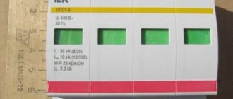
To protect against pulse overvoltages, three surge protection devices (SPDs) FV1–FV3 are installed at the input of the ASU, which are protected by three fuses FU1–FU3 with a rated current of 32 A. The fuses are connected to the input terminal blocks of the ASU.
To account for electricity, the input distribution device uses a three-phase direct-connection PI electricity meter with a rated current of 5–65 A.
After the electricity meter, a four-pole differential current device QF2 type A, type S is installed, without built-in overcurrent protection (VDT), having a rated current of 63 A and a rated residual current of 0.3 A (indicated on the circuit diagram - 63, 0.3 S ). This introductory UDT controls the insulation quality of all electrical equipment used in the electrical installation of an individual residential building. The main purpose of this UDT is to prevent fires in the electrical installation of the house, which may occur due to partial damage to the insulation of any live parts. Type S UDT operates with a time delay and therefore allows for selective operation with other general-purpose UDTs installed in the ASU under consideration.
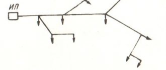
The electrical wiring of the following final electrical circuits (through appropriate protective devices) is connected to the busbars of the input distribution device, which consist of three phase (L1, L2, L3), neutral (N) and protective (PE) busbars:
- gr. 1 – lighting of the ground floor;
- gr. 2 – lighting of the first floor;
- gr. 3 – attic lighting;
- gr. 4 – plug sockets on the ground floor;
- gr. 5 – washing machine socket;
- gr. 6 – plug sockets on the first floor;
- gr. 7 – kitchen plug sockets;
- gr. 8 – dishwasher socket;
- gr. 9 – attic plug sockets;
- gr. 10 – garage plug sockets;
- gr. 11 – single-phase electric water heater;
- gr. 12 – single-phase reserve group;
- gr. 13 – heating boiler control systems;
- gr. 14 – single-phase submersible electric pump;
- gr. 15 – three-phase plug connector installed in the garage;
- gr. 16 – three-phase reserve group.
To protect wires and cables from short circuits and overloads, the input distribution device is equipped with two-pole circuit breakers (for single-phase electrical circuits) and four-pole circuit breakers (for three-phase electrical circuits), which have rated currents of 10 or 16 A and instantaneous tripping type C (indicated on the circuit diagram - C10, C16). These circuit breakers are used to automatically turn off the power.
To provide additional protection against electric shock, as well as to provide protection in case of damage (in addition to circuit breakers) in electrical circuits gr. 1–12, 15 and 16 there are four-pole UDTs of type A, general use, without built-in overcurrent protection with a rated current of 40 A and a rated residual current of 0.03 A (indicated on the circuit diagram - QF3, QF7, QF11, QF15 and QF22 ).
Option 3
As I wrote above, all groups of sockets must have protection against current leakage, that is, they must be protected using an RCD. The third version of the circuit presents an introductory RCD, which is installed after the meter. An RCD cannot be installed before the metering device, since it will need to be sealed, which inspectors do not want to do. That's why they only allow it to be placed after the counter.
To protect people, you need to use an RCD with leakage currents of 10-30mA. This is a safe current for a person, in which he is able to withdraw his hand and not receive any injury. The option using one 30mA RCD at the input has one drawback. When it is triggered, the entire apartment, house, etc. is switched off. Also, if the network is highly branched, then the RCD may trigger falsely due to natural leakage currents that are present in every household appliance.
In this embodiment, phase and zero are supplied to the input contacts of the RCD. Next, from the output contacts, the phase is supplied to the circuit breakers, and the zero is supplied to its zero bus. Remember that the zero before the RCD and the zero after it cannot be combined with each other, that is, connected to one bus. Otherwise, you simply will not arm the residual current device, as it will immediately turn off.
Design
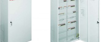
The ASU under consideration meets the requirements for Class I electrical equipment. A box-type ASU (Fig. 2 and 3) is intended for open installation on a vertical wall. The ASU body is a metal box with a single door measuring 950x550x215 mm. It provides protection degree IP43.
Rice. 2. General view of the ASU with a closed (A) and open door (B) (based on Figure 6.12 from the book [1] by Yu.V. Kharechko)
The ASU housing contains mounting panels intended for installation of circuit breakers, differential current devices, terminal blocks, busbars and other electrical equipment. The panel covers are made of insulating material. They prevent access to live parts of the ASU. All panels are 250 mm wide. Between the left and right panels of the ASU there is a panel separator made of insulating material.
Rice. 3. Appearance of the ASU with the panel covers removed (based on Figure 6.13 from the book [1] by Yu.V. Kharechko)
The upper part of the left mounting panel of the ASU (Fig. 4) is used to make an input block and an electricity metering block. The following electrical equipment is installed on this part of the panel:
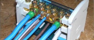
- input spring clamp blocks, which are designed to connect phase conductors and the PEN conductor of the electrical input circuit, as well as phase, neutral and protective conductors of the internal electrical circuit of the ASU. These terminal blocks allow the connection of conductors with a cross-section of up to 16 mm2;
- input four-pole circuit breaker QF1 series S 200 with all protected poles, which has a rated current of 50 A, rated short-circuit switching capacity of 6000 A, instantaneous tripping type C;
- four-pole RCCB QF2 type A, type S, having a rated current of 63 A and a rated residual current of 0.3 A;
- electronic three-phase direct-connection electric energy meter PI, which has a rated current of 5 A, a maximum current of 65 A and a rated voltage of 230/400 V;
- fuses FU1–FU3 with a rated current of 32 A;
- SPD FV1–FV3 with a pulse current of 25 kA, an accompanying current of 15 kA, a rated voltage of 230 V and a protection voltage level of 1500 V.
Rice.
4. ASU top panels with covers removed: 1 – input terminal blocks; 2 – automatic switch QF1; 3 – electricity meter; 4 – fuses FU1–FU3; 5 – SPD FV1–FV3; 6 – VDT QF2; 7 – busbars L1, L2, L3, N; 8 – automatic switches QF19 and QF20; 9 – VDT QF3; 10 – automatic switches QF4, QF5 and QF6; 11 – VDT QF7; 12 – automatic switches QF8, QF9 and QF10 (based on Figure 6.14 from the book [1] by Yu.V. Kharechko) The upper part of the right mounting panel of the ASU (Figure 4) is used to make a distribution block. The following electrical equipment is installed on this part of the panel:
- four-pole RCCBs QF3 and QF7 type A, for general use, having a rated current of 40 A and a rated residual current of 0.03 A;
- double-pole circuit breakers of the S 200 series with all protected poles, which have instantaneous tripping type C, a rated short-circuit switching capacity of 6000 A and a rated current of 10 A (QF4, QF5, QF6 and QF19) or 16 A (QF8, QF9, QF10 and QF20);
- busbars L1, L2, L3 and N, made on the basis of a four-pole distribution block with a rated current of 125 A and allowing the connection of 10 conductors with a cross-section of up to 16 mm2 and 2 conductors with a cross-section of up to 35 mm2.
“Input terminal blocks intended for connecting phase conductors are gray, neutral conductors are blue, PEN conductors and protective conductors are yellow-green. The terminal blocks for phase conductors are connected in pairs using two jumpers. The terminal blocks for neutral conductors and protective conductors are also connected to each other using jumpers. These terminal blocks separate the PEN conductor into neutral and protective conductors. »
[2]
A QF1 circuit breaker is connected to the phase and neutral input blocks of the ASU terminals. Fuses FU1–FU3 are also connected to the phase input terminal blocks, and through them – SPDs FV1–FV3. The electricity meter PI and the RCCB QF2 connected to it are connected to the input circuit breaker QF1. Busbars are connected to the QF2 RCCB, which includes three phase busbars (L1, L2, L3) and a neutral busbar (N).
The lower parts of the left and right mounting panels are also used to make the distribution block (Fig. 5). The following electrical equipment is installed on the lower left panel:
Rice. 5. Bottom panels of the ASU with covers removed: 1 – PE protective busbar; 2 – VDT QF11; 3 – automatic switches QF12, QF13 and QF14; 4 – three-pole terminal blocks for connecting conductors of single-phase electrical circuits (group 1–14); 5 – five-pole terminal blocks for connecting conductors of three-phase electrical circuits (groups 15 and 16); 6 – VDT QF15; 7 – automatic switches QF16, QF17 and QF18; 8 – VDT QF22; 9 – circuit breakers QF21 and QF23 (based on Figure 6.15 from the book [1] by Yu.V. Kharechko)
- PE protective busbar, which is part of the ASU busbars, which is made on the basis of a busbar that allows the connection of 6 conductors with a cross-section of up to 16 mm2 and 21 conductors with a cross-section of up to 4 mm2;
- four-pole RCCB QF11 type A, for general use, having a rated current of 40 A and a rated residual current of 0.03 A;
- double-pole circuit breakers QF12, QF13 and QF14 of the S 200 series with all protected poles, which have a rated current of 16 A, a rated short-circuit switching capacity of 6000 A and instantaneous tripping type C;
- three-pole spring terminal blocks for connecting phase, neutral and protective conductors with a cross-section of up to 4 mm2 of single-phase final electrical circuits (group 1–14);
- five-pole spring terminal blocks for connecting phase, neutral and protective conductors with a cross-section of up to 4 mm2 of three-phase final electrical circuits (groups 15 and 16).
The following electrical equipment is installed on the bottom of the right mounting panel:
- four-pole RCCBs QF15 and QF22 type A, for general use, having a rated current of 40 A and a rated residual current of 0.03 A;
- double-pole circuit breakers QF16, QF17 and QF18 of the S 200 series with all protected poles, which have a rated current of 16 A, a rated short-circuit switching capacity of 6000 A and instantaneous tripping type C;
- four-pole circuit breakers QF21 and QF23 of the S 200 series with all protected poles, which have a rated current of 10 A, a rated short-circuit switching capacity of 6000 A and instantaneous tripping type C.
The internal electrical circuits of the ASU from the input terminal blocks to the busbars (including the PE protective busbar) and from the busbars to four-pole RCCBs are made of insulated flexible copper conductors with a cross-section of 16 mm2. The remaining electrical circuits inside the ASU up to the terminal blocks intended for connecting the conductors of the final electrical circuits are made of insulated flexible copper conductors with a cross-section of 4 mm2.
For every three two-pole circuit breakers connected to one four-pole RCCB, the input (upper) terminals of the poles to which the neutral conductors must be connected are connected to each other by a connecting bus with blue insulation. It is used to make an electrical circuit of a neutral conductor. The output (lower) terminal of the switching neutral pole of a four-pole RCCB is connected via a neutral conductor to one of the specified input terminals of two-pole circuit breakers.
“Metal racks and mounting rails of ASU panels are used as protective conductors. The input protective terminal block has a special conductive part, which forms an electrical contact with the mounting rail. All terminal blocks intended for connecting protective conductors of final electrical circuits also have special conductive parts that form electrical contacts with mounting rails. By means of the specified conductive parts of the terminal blocks and metal structures in the input distribution device, internal electrical circuits of protective conductors are formed. In addition, one of the terminals of the input protective terminal block is connected by a protective conductor to a protective bus, which, in turn, is additionally connected by protective conductors to the metal frames of the ASU mounting panels. »
[2]