- Products
- Strain gauges
- Chemicals and accessories
- Static data acquisition systems
- Dynamics
- Indicators
- Automotive measuring systems
1st method:
With temperature compensated strain gauge: not applicable; With temperature compensated wire: not applicable; Output signal multiplier: x1; Strain factor correction for wire resistance: Description: A typical uniaxial strain measurement where the effect of temperature changes can be neglected. K0—corrected strain gauge coefficient; K is the initial strain sensitivity coefficient; R is the resistance of the strain gauge; r is the total resistance of the wire per meter of length; L is the length of the wire in meters.
2nd method:
With temperature compensated strain gauge: not applicable; With temperature compensation wire: available; Output signal multiplier: x1; Strain factor correction for wire resistance: Description: A typical uniaxial strain measurement. The temperature influence of the wire is eliminated. K0—corrected strain gauge coefficient; K is the initial strain sensitivity coefficient; R is the resistance of the strain gauge; r is the total resistance of the wire per meter of length; L is the length of the wire in meters.
3rd method:
With temperature compensated strain gauge: not applicable; With temperature compensated wire: not applicable; Output signal multiplier: x1; Correction of the strain gauge coefficient for wire resistance: Description: Measurement of uniaxial strain (Output signal is the average value of two strain gauges). Bending deformation is eliminated. K0—corrected strain gauge coefficient; K is the initial strain sensitivity coefficient; R is the resistance of the strain gauge; r is the total resistance of the wire per meter of length; L is the length of the wire in meters.
4th method:
With temperature compensated strain gauge: not applicable; With temperature compensation wire: available; Output signal multiplier: x1; Correction of strain gauge coefficient for wire resistance: Description: In addition to the above, the temperature effect of the wire is eliminated. K0—corrected strain gauge coefficient; K is the initial strain sensitivity coefficient; R is the resistance of the strain gauge; r is the total resistance of the wire per meter of length; L is the length of the wire in meters.
5th method:
With temperature compensated strain gauge: not applicable; With temperature compensated wire: not applicable; Output signal multiplier: x1; Correction of strain gauge coefficient for wire resistance: Description: Measurement of uniaxial strain (Output signal is the average value of four strain gauges). Bending deformation is eliminated. With a 3-wire connection, the temperature influence of the wire is eliminated. K0—corrected strain gauge coefficient; K is the initial strain sensitivity coefficient; R is the resistance of the strain gauge; r is the total resistance of the wire per meter of length; L is the length of the wire in meters.
How to setup
On the front panel of the 4-channel amplifier there are controls and switches that set various parameters. You must make sure that the power indicator is on and the protection alarm is not on before setting up the amplifier. Otherwise, the problem is detected and corrected.
The first stage of setting up a bridge amplifier is to adjust the input level necessary to match the radio. This indicator is set using a regulator or switch. If the radio is connected to high-level inputs, then this control is first set to the 6 V position. Then the lowest input level is set at which the sound remains undistorted when the volume control of the radio is in the high position. After this, the amplifier is configured for all other parameters.
If a subwoofer is connected to the device, you must turn on the low-pass filter, if it is provided for in the amplifier design. The cutoff frequency is initially set at 65-85 Hz and then adjusted more subtly by ear to achieve the desired sound quality depending on the size of the subwoofer and where it is installed.
Some devices have additional controls for more precise adjustments. For example, using an ultra-low-pass filter, you can filter out sounds below 20 Hz to reduce unnecessary load on all speakers and thereby optimize the power consumption of the amplifier.
Hi all. The topic arose from work that was quite simple at first glance. It would seem that what could be simpler than connecting a speaker to an amplifier? In practice, the audiophile masses were puzzled by the massive arrival of double-winding subs in the budget segment. This caused a lot of difficulties for novice car audio connoisseurs. Especially for those who fooled around in physics at school and for those who can’t find anything other than porn on the Internet :D. So today we’ll try to understand this issue, of course, by dispelling a couple of myths and noting a few facts on this topic. In general, let's start with myths.
1) A two-winding sub is NOTHING better than a single-winding one! It is simply more convenient to switch and nothing more. Under equal conditions, a similar sub with one winding of similar impedance will work better.
2) On acoustics, it is indicated not the resistance but the IMPEDANCE. Impedance consists of active resistance, which is determined by the coil itself, and the reactance that arises during operation of the speaker. So what is indicated on the acoustics is the value below which the impedance will not fall. That is, if you measure the speaker resistance with a device, the figure will be less than indicated. (for example, for a speaker with an impedance of 4 ohms, the resistance will be 3.6-3.7 ohms) And on a working 4-ohm speaker, the impedance can double or even triple depending on the frequency. These flights will depend on 100,500 factors, including the design of the din, port settings and even open cabin windows. This is precisely why it is stupid to say that your device is completely dumping its declared power into the speaker. Perhaps in your case it does not deliver even half of its real power and at the same time clips. But this is all lyrics. Don’t bother your head with this, the main thing is for the bufak to hammer home and this is not what we’re talking about.)) The main thing is to understand what’s what, at least in general terms.
3) If it is indicated that the amplifier should operate at 4 ohms, is that exactly what it needs, no more, no less? That's not true! This application of the amplifier suggests that LESS than this impedance should not be connected to the control unit because it will overload it. Cling as much as you like. at least 100500 ohms. The higher the resistance, the easier it is for the amplifier to work, the less it will heat up, the less power it will deliver and the sooner it will clip. Accordingly, the less impedance we put on the amplifier, the more power it will try to deliver (it’s not a fact that it will deliver. Everything will depend on the amplifier’s power supply), the more it will heat up and the more power it will naturally want. My personal advice: follow the manufacturer’s recommendations, especially if you have little experience with car audio.
With myths and legends, everything I heard seems to have been sorted out. Now let's remember a little about physics. A two-winding sub has 2 windings with their own 2 pairs of leads each. According to the connection diagrams, a two-winding sub is simply similar to 2 subs with one coil in each. (Do not be confused! A two-winding sub will not work like 2 single-coil ones! Roughly speaking, one coil is simply divided into 2 and this division does not give the sub any special advantages from the point of view sound). A two-winding sub, like a pair of single-coil subs, can be connected in 3 ways. Series, parallel and when using a two-channel amplifier, channel by channel. Physics teachers told us all at school that when consumers are connected in series, their resistance SUMMARIZES. For double-students: a series connection of speakers will look like this:
6th method:
With temperature compensation of strain gauge: available; With temperature compensation wire: available; Output signal multiplier: x1; Correction of strain gauge coefficient for wire resistance: Description: Measurement of uniaxial strain; The passive strain gauge must be of the same type and batch as the active strain gauge, bonded to the same type of material, and placed in the same environment, including wire. K0—corrected strain gauge coefficient; K is the initial strain sensitivity coefficient; R is the resistance of the strain gauge; r is the total resistance of the wire per meter of length; L is the length of the wire in meters.
§ 12. Bridge circuit for connecting resistors and its application
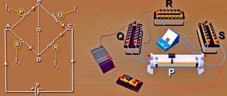
For electrical measurements, as well as in some other cases, resistors are connected according to an electrical bridge circuit, or bridge circuit (Fig. 28, a). Resistors with resistances R1, R2, Rз, R4 form the so-called bridge arms. The sections of the chain connecting points a and c, as well as b and d, are called bridge diagonals. Typically, one of the diagonals, in this case ac (supply diagonal), is supplied with voltage U from a source of electrical energy; in the other diagonal bd (measuring diagonal) an electrical measuring instrument or some kind of apparatus is included. If the resistances R1=R4 and R2=R3 are equal, the voltages in sections ab and ad from currents I1 and I2 (as well as in sections bc and dc) will be the same, therefore points b and d will have the same potentials. Consequently, if you include any resistor R or an electrical measuring device in the diagonal bd, then in the diagonal I = 0 (Fig. 28, b). Such a bridge is called balanced. For the bridge to be balanced, it is necessary that the voltages Uab= Uad and Ubc=Udc; these conditions occur not only when the resistances R1=R4 and R2=R3 are equal, but also when the ratios R1/R4=R2/R3 are equal. Consequently, the bridge will be balanced when the products of the resistances of the resistors connected to its opposite shoulders are equal: R1R3 = R2R4. If this condition is not met, current I will flow through resistor R; such a bridge is called unbalanced. The bridge circuit is also used to activate the slip relay on some electric locomotives. The relay serves as a sensor to detect wheel pair slipping. Relays P (Fig. 29) include
Rice. 28. Bridge circuits for connecting resistors Fig. 29. Scheme for switching on the boxing relay
into the diagonal of the bridge formed by two series-connected electric motors M1 and M2, through which current Id passes (electric motors in this case are considered as sources with emf E1 and E2), and two resistors with resistance R. In the absence of slipping, E1 = E2 , therefore, the currents passing through the resistors are I1 = I2. Therefore, the current in the relay coil is I = I1 – I2 = 0.
When slipping occurs, the rotation speed of the traction motor associated with the slipping wheel pair increases sharply. At the same time, its e.g. increases sharply. d.s, for example E1, and current I1. As a result, a current I=I1-I2 will begin to flow through the relay coil P, which will cause it to operate. Relay P, with its block contact, turns on the alarm and sand supply or affects the control system of the electric locomotive.
7th method:
With temperature compensation of strain gauge: available; With temperature compensation wire: available; Output signal multiplier: x(1+v); Correction of the strain gauge coefficient for wire resistance: Description: Measurement of axial deformation with increased sensitivity (1+v) times. The temperature influence of the strain gauge and wire is eliminated. K0—corrected strain gauge coefficient; K is the initial strain sensitivity coefficient; R is the resistance of the strain gauge; r is the total resistance of the wire per meter of length; L - wire length in meters; v is the Poisson's ratio of the sample.
Bridge connection of amplifier channels (Bridge ON-OFF)
With a bridge connection, the amplifier combines the positive wire of the speaker output of one amplification channel and the negative wire of the speaker output of the second amplification channel. By combining the left and right channels in this way, we get one much more powerful mono channel for connecting a subwoofer to it. Its power is four times greater than the power of one channel before the bridge connection mode, since power is the square of the voltage divided by the resistance, which remains unchanged. Let's say the output voltage on one channel is 15 Volts, therefore its power will be equal to:
15(15/4Ohm) = 56.25 W.
With a bridge connection, the voltage of the combined channel will become equal to 30 Volts, and the power will become equal to:
However, it should be remembered that an increase in power does not lead to a proportional increase in the volume (dB) of the sound. Doubling the power results in an increase in sound pressure level of only 3 dB. In our case, with a fourfold increase in power, the sound pressure will increase by 6 dB.
In order to properly configure the amplifier, you must perform the following steps:
1. Turn the gain control on the amplifier to minimum (minimum gain).
2. Raise the volume on the head unit to the maximum level at which distortion has not yet begun.
3. On the amplifier, slowly raise the gain control to the level before distortion (maximum “clean” gain).
4. Turn down the volume on the head unit to the desired level.
As a result of these actions, we will obtain the maximum sound pressure level (SPL) that the sound system can produce.
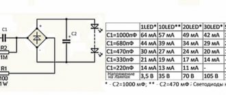
Capacitors are devices that can store and release electrical charge. The capacitance of capacitors is measured in Farads. A capacitor with a capacity of 1 F accumulates an electrical charge equivalent to a current of 1 A lasting 1 second. A charged capacitor discharges very quickly, making it very useful for maintaining power to powerful car audio systems.
The amplifier may briefly consume up to three times its average power consumption during operation. During these short periods of time, the car's battery is not able to supply the amplifier with the required current strength, and as a result, a voltage drop occurs in the car's power system, which leads to sound distortion (dull bass). Installing a capacitor successfully solves this problem. The capacitor, quickly discharging, smoothes out the voltage drop in these short periods of time and provides the amplifier with smooth power.
Capacitors for such purposes are available with capacities from 250,000 mF to 2,000,000 mF. Capacitors are selected according to the rule that for every 100 W of amplifier output power, 100,000 mF of capacitor capacitance is installed.
8th method:
With temperature compensation of strain gauge: available; With temperature compensation wire: available; Output signal multiplier: x2; Correction of strain gauge coefficient for wire resistance: Description: Measurement of bending strain with double sensitivity. Axial deformation is eliminated. The temperature influence of the strain gauge and wire is eliminated. K0—corrected strain gauge coefficient; K is the initial strain sensitivity coefficient; R is the resistance of the strain gauge; r is the total resistance of the wire per meter of length; L is the length of the wire in meters.
Why single-pole power supply?
There are several different terms used to describe a system in which the designer has access to both positive and negative voltage rails: bipolar, balanced, dual-supply, separate-supply. Whatever you want to call them, I like them; analog circuits are simpler and (in my opinion) more mathematically coherent, where the signal level can go virtually below ground level.
However, the inescapable fact is that a dual power supply system is usually persona non grata in the world of modern electronics. The reason for this is quite simple: creating a negative voltage source requires additional circuitry, which means more design time, higher cost and larger PCB sizes; thus, if the system requirements can somehow be met without accessing the negative power rail, so much the better. An alternative to additional circuitry is a second battery; In addition to the fact that this approach is only applicable to battery-powered equipment, it still adds cost and bulk that can be eliminated by clever single-power supply design.
Note. There is no law stating that a dual-supply system must have positive and negative supply voltages that are equal in magnitude (i.e., symmetrical). However, symmetrical power supplies are the norm for amplifier circuits, and discussions of dual-supply or split-supply systems may include the assumption that the supply voltages are symmetrical.
9th method:
With temperature compensated strain gauge: not applicable; With temperature compensated wire: not applicable; Output signal multiplier: x2; Correction of the strain gauge coefficient for wire resistance: Description: Measurement of uniaxial strain (Output signal is the sum of the values of two strain gauges). Bending deformation is eliminated. K0—corrected strain gauge coefficient; K is the initial strain sensitivity coefficient; R is the resistance of the strain gauge; r is the total resistance of the wire per meter of length; L is the length of the wire in meters.
10th method:
With temperature compensated strain gauge: not applicable; With temperature compensation wire: available; Output signal multiplier: x2; Correction of strain gauge coefficient for wire resistance: Description: In addition to the above, the temperature effect of the wire is eliminated. K0—corrected strain gauge coefficient; K is the initial strain sensitivity coefficient; R is the resistance of the strain gauge; r is the total resistance of the wire per meter of length; L is the length of the wire in meters.
11th method:
With temperature compensation of strain gauge: available; With temperature compensation wire: available; Output signal multiplier: x2(1+v); Correction of the strain gauge factor for wire resistance: r L should apply to the wire for supplying the excitation voltage, provided that the resistance of the wire within the full bridge circuit is small enough that it can be neglected. Description: Measurement of uniaxial deformation with sensitivity increased by 2(1+v) times. Bending deformation is eliminated. v is the Poisson's ratio of the sample; K0—corrected strain gauge coefficient; K is the initial strain sensitivity coefficient; R is the resistance of the strain gauge; r is the total resistance of the wire per meter of length; L is the length of the wire in meters.
How to connect two amplifiers with a bridge
Master/Slave
Amplifiers designed for this connection have MASTER/SLAVE switches. Therefore, with a bridge connection, one of the amplifiers will be the master ( Master ) and the second will be the slave ( Slave ), set the switches in this accordance. It is to the Master that the interconnect cables (tulips) from the radio are connected, and from it, through a mono connector, the signal is transmitted to the Slave (with a single interconnect). This is done so that all settings and control are carried out from one monoblock - from the Master, that is, gain, filters, subsonic, etc. will be exhibited only there. There is no need to take Y splitters to try to plug interconnects into the Slave as well.
If the manufacturer declares that the amplifier can operate in a bridge, but there are no Master / Slave switches, then it will have two sockets with similar names - Bridge Input and Bridge Output . In this case, use the Bridge Output jack on the master amplifier and connect it to the Bridge Input jack of the slave amplifier.
Connecting speaker wires
Here, be careful and do not confuse anything: we connect the negative connectors of the two amplifiers to each other; then we connect the plus (+) of the Master to the plus of the subwoofer, and the plus of the Slave to the minus of the subwoofer !
Yes, there are two positive wires going to the subwoofer, no need to strain - everything is correct. The fact is that a direct signal is supplied to the input of one amplifier, and for the second the signal is turned 180 degrees. Therefore, at the output of one the positive potential increases, and at the output of the second it is the same but negative. The increase in power occurs because the amplifiers or channels (in the case of using one wuxia) operate at reduced resistance. For example, if the sub is connected to 4 ohms, then each amplifier or channel operates at 2 ohms, etc.
12th method:
With temperature compensation of strain gauge: available; With temperature compensation wire: available; Output signal multiplier: x4; Correction of the strain gauge factor for wire resistance: r L should apply to the wire for supplying the excitation voltage, provided that the resistance of the wire within the full bridge circuit is small enough that it can be neglected. Description: Measurement of bending strain with quadrupled sensitivity. Axial deformation is eliminated. K0—corrected strain gauge coefficient; K is the initial strain sensitivity coefficient; R is the resistance of the strain gauge; r is the total resistance of the wire per meter of length; L is the length of the wire in meters.
More voltage → more power
There are two important benefits associated with a bridge amplifier. The first thing we'll discuss is this: a bridge amplifier allows you to significantly increase the power delivered to your load. How much more? Well, we know that the instantaneous power of an AC voltage signal can be expressed as follows:
\[P_{load} = \left( \frac{V_{peak}}{\sqrt{2}} \right)^2 \times \frac{1}{R}\]
Thus, the power is proportional to the square of the peak voltage. The bridge circuit doubles the voltage across the load; therefore, it provides a fourfold increase in the power delivered to the load. You might be wondering - why can't we just use one op amp and increase the gain to get more voltage? Why bother with a bridge circuit? These are good questions, and the answer is that a bridge amplifier produces Pload that is four times the maximum power you can achieve at a given supply voltage. In other words, a bridge amplifier is especially useful when you are trying to get as much power as possible from your power rail.
In this age of low voltage systems, you may find that the supply voltage is the limiting factor in how much power you can supply to the load. Let's assume that the load resistance is fixed, so you can't increase power by decreasing Rload, and let's also assume that you have sufficient current available from your power supply. In this case, your 3.3V power supply is holding you back - you could easily supply more power if you had a slightly higher supply voltage. Well, that's where a bridge amplifier comes in: the same voltage rail, but four times the power.
13th method:
With temperature compensation of strain gauge: available; With temperature compensation wire: available; Output signal multiplier: x4; Correction of the strain gauge factor for wire resistance: r L should apply to the wire for supplying the excitation voltage, provided that the resistance of the wire within the full bridge circuit is small enough that it can be neglected. Description: Measures torque-induced deformation with four times the sensitivity. Axial and bending deformation are eliminated. K0—corrected strain gauge coefficient; K is the initial strain sensitivity coefficient; R is the resistance of the strain gauge; r is the total resistance of the wire per meter of length; L is the length of the wire in meters.
» >
Strain gauge bridge circuit
pdf, 480.23 KB
Bridge switching circuit.
One of the most common schemes for connecting resistive sensors is bridge
.
A standard bridge circuit is shown in Figure 23.
Figure 23
A bridge circuit is essentially two voltage dividers in parallel
connected to a power source.
This can be clearly seen from the bridge circuit represented as shown in Figure 24. The output signal is taken between
the two outputs of the voltage dividers (points A and B). This type of output is called differential (or balanced) output.
Figure 24
The ground neutral state in a bridge circuit is called bridge equilibrium.
A balanced bridge is a bridge whose output voltage is zero. This condition occurs when the output voltage of one voltage divider is equal to the output voltage of another voltage divider, relative to ground. If you introduce one or more resistive elements with varying resistance into a bridge circuit, you can easily bring the bridge to such a balanced state. Bridge equilibrium occurs if the bridge resistances are related by the following relationship:
R1/R2= R3/R4
If instead of one of the bridge resistors (for example, R2), you turn on a resistive sensor (say, a thermistor), and instead of R1 - a trimming resistor and then balance the bridge, then any change in the resistance of the sensor will lead to unbalancing of the bridge and the appearance of voltage on the load. Moreover, the polarity of this voltage will depend on which direction the resistance has changed. Thus, the voltage across the load will be a measure of the deviation of the sensor resistance from the original value. In our example, this voltage will also be a measure of the temperature deviation from the original value. If the relative change in resistance is no more than a few percent, then the dependence of the load voltage on the change in resistance can be considered linear.
This principle is used to build bridge circuits for measuring transducers of temperature (using thermistors), strain (using strain gauges), magnetic field (using magnetoresistors), etc.