For many years now we have been using conventional incandescent lamps to illuminate our homes, apartments, offices or industrial plants. However, every day electricity prices are rapidly rising, which forces us to give preference to more energy-efficient devices that have high efficiency, long service life and are capable of creating the necessary luminous flux at minimal cost. These devices include 220-volt LED lamps, the advantages of which we will try to fully reveal in this article.
Attention! This publication provides examples of circuits powered by a life-threatening voltage of 220V. Only persons with the necessary education and permits are allowed to assemble and test such circuits!
The simplest scheme
A 220 V LED lamp is one of the types of lighting lamps in which the luminous flux is created by converting electrical energy into luminous flux using an LED crystal. To operate LEDs from a stationary household 220 V network, you need to assemble the simplest circuit shown in the figure below.
The circuit of a 220-volt LED lamp consists of an alternating voltage source of 220–240 V, a rectifier bridge for converting alternating current into direct current, a limiting capacitor C1, a capacitor for smoothing ripples C2 and LEDs connected in series from 1 to 80 pieces.
Principle of operation
When an alternating voltage of 220 V of variable frequency (50 Hz) is supplied to the LED lamp driver, it passes through the current-limiting capacitor C1 to a rectifier bridge assembled from 4 diodes.
After this, at the output of the bridge we receive a constant rectified voltage required for the operation of the LEDs. However, to obtain a continuous light output, it is necessary to add an electrolytic capacitor C2 to the driver to smooth out the ripples that occur when rectifying the alternating voltage.
Looking at the design of a 220-volt LED lamp, we see that there are resistances R1 and R2. Resistor R2 is used to discharge the capacitor to protect against breakdown when the power is turned off, and R1 is used to limit the current supplied to the LED bridge when turned on.
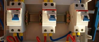
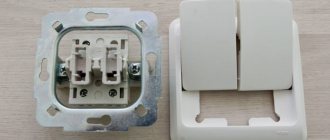
Connection via one-key switch
The connection diagram for a luminaire via a single-key switch is the simplest of the considered range of possible load switching methods. To implement it, you will have to perform the following sequence of mandatory operations:
- First of all, you will need to remove the supply voltage of 220 volts from this line (this is easiest to do using an input or linear machine).
- After this, you need to make sure that it is absent using an indicator screwdriver or a special measuring device - a multimeter (it is switched on in the mode of measuring alternating voltages at a limit of up to 750 volts).
- Then you need to remove the key from the switch by prying it from the side with a thin-bladed screwdriver.
- Next, you need to fix the switch body in a niche prepared in advance in the wall and carefully bring the two wires connected to it out.
- Inside the open base, you need to find two contacts, to one of which (the bottom) the wire suitable from below is connected, and to the second (top) the end that goes directly to the lighting device is connected.
Important! The procedure for connecting wires to the switch is strictly regulated by the requirements of the PUE.
As a result of these manipulations, a switch with one key will be connected to a phase wire break.
Thanks to this circuit, it will be possible to supply 220 volt power directly to the lamp.
Circuit with active current limiter
In this version of the circuit, the current-limiting element is resistance R1. Such a circuit will have a power factor or cos φ close to unity, unlike previous options with a current-limiting capacitor, which are a reactive load. The disadvantage of this option is the need to dissipate a significant amount of heat on resistor R1.
To discharge the residual voltage of capacitor C1 to zero, resistor R2 is used in the circuit.
Installation of LED lamps for 220V AC circuits
LED light bulbs consist of the following components:
- Base (E27, E14, E40 and so on) for screwing into the socket of a lamp, sconce or chandelier;
- Dielectric gasket between the base and the housing;
- A driver on which a circuit is assembled to convert alternating voltage into a constant voltage of the required value;
- A radiator that serves to remove heat from the LEDs;
- A printed circuit board onto which LEDs are soldered (sizes SMD5050, SMD3528, and so on);
- Resistors (chips) to protect LEDs from pulsating current;
- Light diffuser to create a uniform light flux.
Effect of an illuminated switch on an LED lamp
If the LED lamp flickers when turned off, check that the backlight switch has an indicator, which is represented by a small neon or LED light bulb. If there is one, that's the problem.
The indicator turns on if the lighting is turned off and the electrical circuit is open. The circuit is designed in such a way that the backlight is connected to the switch in parallel. When we turn off the lights, current flows to the indicator. Electricity moves in a circle, from the network to the switch light, then to the lamp and back to the network. This voltage allows you to charge the capacitor found in most LED lights. As a result, the capacitor tries to turn on the lamp, but there is too little charge, so flickering occurs in the lighting fixture or the LED may constantly burn dimly.
How to connect 220 volt LED lamps
The biggest trick when connecting 220 V LED lamps is that there is no trick. The connection is exactly the same as you did with incandescent lamps or compact fluorescent lamps (CFLs). To do this: turn off the power to the base, and then screw the lamp into it. When installing, never touch the metal parts of the lamp: remember that sometimes careless electricians can pass zero through the switch instead of a phase. In this case, phase voltage will never be removed from the base.
Manufacturers have released LED analogues of all previously produced types of lamps with a variety of sockets: E27, E14, GU5.3 and so on. The installation principle for them remains the same.
If you bought an LED light bulb designed for 12 or 24 Volts, then you cannot do without a power supply. The light sources are connected in parallel: all the “pluses” of the light bulbs together to the positive output of the power supply, and all the “minuses” together to the “minus” of the power supply.
In this case, it is important to maintain polarity (“plus” to “plus”, “minus” to “minus”), since the LEDs will only emit light if the polarity is correct! Some products may fail if polarity is reversed.
Attention! Do not confuse a DC power supply (power supply) with a transformer. The transformer produces an alternating voltage output, while the power source produces a constant voltage.
For example, you have furniture lighting in the kitchen, wardrobe or other place, made up of 4 halogen lamps with a power of 40 W and a voltage of 12 V, powered from a transformer. You decide to replace these lamps with 4 LED lamps of 4–5 W each.
Attention! In this case, it is necessary to replace the previously used transformer with a 12 V DC source with a power of at least 16–20 W.
Sometimes such LED lamps for spotlights are in most cases equipped with a power supply at the factory. When purchasing such lamps, you should also consider purchasing a power source.
Connecting the illuminator from an outlet
In a situation where the switch is installed in a new place (in the absence of a special niche), it can be mounted directly on the wall and powered from a nearby outlet. In this case, before connecting the lamp through the switch, it is necessary to extend the phase and zero from it, as shown in the photo below. In certain conditions, one phase is sufficient for this, since the neutral wire is already connected to the wall lights from the junction box.
Before connecting lamps with a switch from the nearest outlet, you need to familiarize yourself with the features of this procedure. The order of its execution looks like this:
- First, an indicator screwdriver is taken, with which the phase wire is determined and remembered, from which the wire is subsequently routed to the switch (it can be located either on the right or on the left).
- After this, the dangerous voltage of 220 volts is removed from the line, in which a switch is installed along with sockets, using an automatic machine.
- To be sure of its absence, it is advisable to check it with an indicator screwdriver.
- Before connecting the lamp through the switch from the socket, you need to remove the decorative cover from it, under which there are two contacts.
- A conductor of the required length is connected to one of them (phase) and routed to a single switch.
Upon completion of the preparatory procedures, the wire coming from the outlet is supplied to the switch mounted on the wall with the cover removed (it is connected to its lower terminal). Another conductor is pulled from the top contact towards the lamp, which is placed in a cable channel or tubular corrugation for aesthetics. In the same way, you can close the wire in the area from the outlet to the switch.
Connection diagram for a luminaire via a switch in a combined socket-switch unit in one housing:
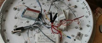
How to make a simple LED light bulb
In order to assemble an LED lamp, we need an old fluorescent lamp, or rather its base with a base, a long piece of 12 V LED strip,
and an empty aluminum 330 ml can
To power such a lamp, you will need a 12 V DC source of such a size that it can fit inside the can without any problems.
So, now the production itself:
- Wrap the ribbon around the jar as shown in the picture.
- Solder the wires from the LED strip to the output of the power supply (PS).
- Solder the IP input with wires to the base of the lamp base.
- Securely secure the source itself inside the jar, having previously cut a hole large enough to allow the power source to pass inside.
- Glue the can with tape to the base of the body with the base and the lamp is ready.
Of course, such a lamp is not a masterpiece of design art, but it is made with your own hands!
Group connection of luminaires
By group we mean the connection of several lamps to one source. There are also 2 cases to consider:
- Group connection of luminaires with built-in drivers.
- Connecting several lamps to one driver/voltage stabilizer.
Connecting luminaires with built-in drivers
In this case, two options should be considered: serial and parallel connection.
Sequential
This option can be used when there are several devices of the same type with an input operating voltage less than the mains voltage.
So, if there are lamps with 12 V drivers, you can assemble 20 pieces in series to distribute the input voltage between the devices, as shown in the figure.
The option is workable, but has several significant disadvantages:
- The whole number of devices does not allow you to accurately select the number of devices for the input voltage. A small deviation can only be obtained if there is a significant difference between the mains voltage and the input driver, i.e. with a relatively large number of devices connected in series. So, when assembling 20 lamps with 12 V drivers, the required voltage is 240 V; with a network voltage of 220 (230 V), the deviation is less than 10% and the devices remain operational. With a small difference (hypothetical option - 3 lamps with 90 V drivers), the voltage will be distributed at 73 V to each input. The deviation from the nominal value is greater than acceptable (almost 20%) and correct operation of the devices is not guaranteed.
- For uniform voltage distribution, it is necessary to select devices with identical input characteristics (in particular, resistance). Otherwise, a significant imbalance is possible; some devices will not receive the required supply voltage, while on others it will exceed the rated value. External equalizing devices, for example, a resistive-capacitive divider, will help solve the problem.
- The failure of one of the drivers automatically breaks the entire circuit.
- Most devices (both drivers and luminaires) are at floating potential, which can pose a serious danger.
- There is a significant influence of the driver input circuits on each other.
These arguments are quite enough to refuse this option of using lighting equipment.
Parallel
In this option, all lamps are connected to one pair of network wires. In fact, this is equivalent to connecting several independent consumers. Accordingly, such a connection does not have any significant disadvantages or limitations.
The only requirement is that the total current consumed from the network must be less than the trigger level of the protective equipment.
Some electricians note that there may be a difference in the brightness of the glow. This is natural if the parameters of the LEDs in the lamps and drivers are noticeably different. The problem is easily solved by selecting products (if not individually, then at least from one batch).
Group connection of luminaires to one driver/voltage stabilizer
Serial, parallel and mixed connection options are available.
Sequential
For such a connection, it is necessary that the total voltage drop across the LED devices falls within the range of permissible output voltages of the driver. In this case, the same current flows through all devices, equal to the output current of the LED driver.
Naturally, some disadvantages remain:
- Due to the difference in the characteristics of individual devices, the total voltage may exceed the nominal nominal value. Accordingly, the upper limit of the driver output voltage should be selected with a margin.
- If there is a break in one of the lamps, the entire chain becomes inoperable.
Despite these disadvantages, a serial connection is the recommended choice when working with a current stabilizer driver.
Parallel
When connected in parallel to a current source, uneven current distribution between branches is observed due to differences in the characteristics of the devices. As a result, the devices will have a different glow. That is why it is not recommended to use this option with drivers - current stabilizers.
A good method is to connect lamps in parallel to a voltage source. In this case, current-limiting elements will have to be introduced into each branch.
For your information! When connecting several segments of an LED strip to a power source, it is recommended to use parallel rather than serial connections, even if the segments have different lengths.
Combined
This type of connection works well for both current and voltage sources.
An example for illustration is the option of connecting 30 LEDs with a current of 100 mA and a voltage drop of 3.3V to a current source of 600 mA or a voltage source of 20V.
Naturally, to connect you will have to combine - connect the lamps in series and in parallel.
2 extreme cases:
- Assemble blocks of 5 LEDs in parallel, then turn on 6 such blocks in series.
- Collect branches of 6 serial sources, and connect 5 such branches in parallel.
In the first case, blocks with a rated current of 500 mA are assembled, in the second - branches with a rated voltage of 16.5 V.
When connected to a current source according to the second option, the whole branch will glow unevenly. But the first option will result in uneven illumination of only some LEDs of one block. Accordingly, it is more profitable for a current stabilizer to assemble modules from several parallel lamps and connect them in series.
Similarly, parallel connection of branches to the voltage source allows us to minimize the influence of component scatter, and series of blocks will only emphasize this problem.
Practical note! When sets of LEDs with obviously different parameters (for example, different colors) are connected, it is necessary to distribute them evenly across blocks and branches, so that each structural element is similar to the others. For example, if in the considered example you need to connect 18 white and 12 green LEDs in series, they need to be arranged in blocks of 3 white and 2 green.
Thus, to properly connect LED lamps to a 200 V network, you need to perform 3 main steps:
- Select the type of power source (current or voltage stabilizer).
- Determine the connection diagram.
- Calculate the load parameters and select the power source.
The main malfunctions of 220 volt LED lamps
Based on many years of experience, if a 220 V LED lamp does not light, then the reasons may be as follows:
Failure of LEDs
Since in an LED lamp all the LEDs are connected in series, if at least one of them goes out, the entire lamp stops lighting due to an open circuit. In most cases, LEDs in 220 lamps are used in 2 sizes: SMD5050 and SMD3528.
To eliminate this reason, you need to find the failed LED and replace it with another one, or install a jumper (it is better not to abuse jumpers - as they can increase the current through the LEDs in some circuits). When solving the problem using the second method, the luminous flux will decrease slightly, but the light bulb will begin to shine again.
To find a damaged LED, we need a low current power supply (20 mA) or a multimeter.
To do this, we apply “+” to the anode and “–” to the cathode. If the LED does not light up, it means it is faulty. Thus, you need to check each of the lamp LEDs. Also, a failed LED can be identified visually; it looks something like this:
The cause of this failure in most cases is the lack of any protection for the LED.
Failure of the diode bridge
In most cases, with such a malfunction, the main reason is a manufacturing defect. And in this case, the LEDs often “fly out”. To solve this problem, you need to replace the diode bridge (or bridge diodes) and check all the LEDs.
To check the diode bridge you need a multimeter. It is necessary to apply an alternating voltage of 220 V to the bridge input and check the voltage at the output. If it remains variable at the output, then the diode bridge has failed.
If the diode bridge is assembled on separate diodes, they can be unsoldered one by one and checked with a device. A diode must pass current in only one direction. If it does not pass current at all or does pass it when a positive half-wave is applied to the cathode, then it is out of order and requires replacement.
Poor soldering of lead ends
In this case, we will need a multimeter. You need to understand the circuit of the LED lamp and then check all the points, starting with the input voltage of 220 V and ending with the LED outputs. Based on experience, this problem is inherent in cheap LED lamps and to eliminate it, it is enough to additionally solder all the parts and components with a soldering iron.
Required Tools
Tool for stripping wires - stripper
To connect lighting fixtures with your own hands, you will need the following working tools:
- set of screwdrivers (flat and Phillips);
- a tool designed to expose wires (remove the insulating layer);
- pliers.
As practice shows, it takes no more than 10-15 minutes to install the device yourself.
Where to buy a lamp
You can resolve the issue as quickly as possible in the nearest specialized store. The optimal option, in terms of price-quality ratio, remains purchasing from the AliExpress online store. Mandatory long waits for parcels from China are a thing of the past, because now many goods are in intermediate warehouses in destination countries: for example, when ordering, you can select the “Delivery from the Russian Federation” option:
| Nieuwe MR16 GU5.3 High Power LED Flood Light 6W 9W 12W | LED lamp Ampoule, E14, E27, GU10 | LED lamp with Bluetooth, E27, E14, GU10, RGB |
| LED spotlight E27, GU10, E14 | LED lamp for home | LED chandelier with a unique design |