Today many people are already familiar with the concept of RCD. The installation of these devices is necessary if we take care of ourselves and our loved ones, and want to have a safe electrical network in our homes. Many people ignore these residual current devices - some don’t want to redo the switchboard, for others it’s too expensive. And it’s completely in vain, because the RCD connection diagram is not complicated. As for financial costs, there are variants of schemes when only one device is mounted at the input. You can fork out for this, especially if we are talking about the safety of human life.
Getting to know your device
Before connecting the RCD, it would be nice to understand its design, operating principle and main functions.
Why is it necessary?
The main task of an RCD is to protect people from electric shock. A person may accidentally touch exposed live wires. Or touch the body of a household electrical appliance on which potential has appeared due to insulation damage. In any of these cases, the device will work and the voltage supply will stop.
It also protects our home from fire, which can be caused by current leaks or ground faults. The fact is that in these cases, the magnitude of the current is not enough to turn off the circuit breaker, designed to work with overcurrents of overload and short circuit.
Similarities and differences between RCDs and automatic machines
The appearance, design and main parameters of the residual current device are very similar to circuit breakers. Both of these switching devices are used in both single-phase and three-phase network circuits. The main task of both RCDs and automatic devices is to instantly cut off the damaged section of the electrical network in emergency situations.
The only difference is that the circuit breaker operates with large currents (in case of overloads and short circuits, they exceed the operating current of the circuit breaker itself). And to trigger the RCD, a small leakage current is enough.
To ensure that high currents at the time of an accident do not have a negative impact on the residual current device, it must be connected to the circuit together with the circuit breaker.
If you look at the appearance of the RCD and the machine, you will not find any special differences; it seems that they are the same device.
But you just have to take a closer look at the diagrams and numbers drawn on the case, and it will immediately become clear where the device is.
- Their rated operating voltage will be the same - 220 V or 380 V.
- The operating current may also be the same, which is classified according to a special scale (10, 16, 25, 32 A). Operating current is the maximum current at which the device operates normally.
- The fundamental difference will be such a parameter as the magnitude of the leakage current. You won’t find it on the machine, but on the RCD this figure is written and indicated in milliamps. It also has its own standard range - 6, 10, 30, 100 mA.
- An important difference between an RCD and a machine is the “TEST” button. These devices are designed with an additional test circuit that simulates leakage current. Using such a circuit, the serviceable condition of the RCD is checked, and the test is started with the “TEST” button.
The most important difference between automatic machines and RCDs is that the circuit breaker will also work in a two-wire, single-phase network, that is, it only needs a phase and a zero. And in order for the RCD to operate correctly, it is necessary to have a three-wire single-phase network; in addition to phase and zero, there must be a protective grounding.
Safety rules for installing RCDs, meters and machines
The RCD connection is carried out in compliance with safety rules. Your life and health depend on them. The basic principles of safe installation are:
- Work is performed with the voltage turned off. Its absence must be checked with an indicator screwdriver, multimeter or 220V test light.
- Connected wires must be marked. This can be done conveniently using electrical tape or heat-shrinkable tubes of different colors.
- Factory-made terminal blocks are used to connect and extend wires. According to the PUE, twisting is prohibited.
- Each wire connected to an RCD or machine is checked for reliable contact. To do this, it is enough to try to pull out the conductor with a little effort. It should stay in place and not wobble.
- When power is first applied, short circuits and explosions in the electrical panel cannot be ruled out. Therefore, you should protect your eyes and exposed areas of the body and ask bystanders to leave.
- After installation, you should check the operation by pressing the “test” button. Before this, voltage is applied to it.
- Replacement and installation of a new RCD is carried out by at least 2 persons. The second person is the observer.
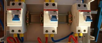
Mounting the machine on a DIN rail
Note! The residual current device is fixed to a DIN rail. This significantly simplifies the installation process. If the shield initially does not have a die for attaching DIN devices, then you will have to purchase it additionally. Many people, when buying RCDs and automatic machines, forget to think about what they will be mounted on.
When choosing an RCD, you should take into account the rated current that it can pass. For an ordinary apartment, 16-32 A is enough. Another selection criterion is the operating current (IDn). If the RCD is to protect a person from electric shock, then it is necessary to set the device to 10-30 mA. If the goal is to save from a fire, the required rating is about 100-300 mA.
The residual current device is installed with voltage relief. There is no need to do the work yourself if you have no experience in assembling circuits. After startup, it is advisable to check the device by pressing the “test” button.
Scheme options
This is not to say that there is one specific pattern. Each case has its own characteristics, so connecting the RCD can be done in different ways. Firstly, the device is used in single-phase and three-phase voltage networks (these are two different circuits). Secondly, you can install an RCD at the entrance and thus protect the entire apartment from current leaks. And you can install devices for each individual line, thereby protecting only a certain section of the electrical network.
Video example of connecting an RCD in a single-phase network:
Since the circuit diagram for connecting an RCD has several options, it is very important that you can read them. Nowadays, the passports of many electrical household appliances and equipment indicate how and through what type of RCD they must be connected to the electrical network.
These recommendations cannot be neglected. Manufacturers of washing machines or microwave ovens write them not out of whim, but for your safety.
Let's look at how to properly connect an RCD using several general examples.
What is a single-phase network?
With a single-phase electrical network, consumers are powered through two conductors - a phase and a working zero. The rated voltage in such networks is 220 V.
A single-phase network can be of two-wire or three-wire design. In the first case, two conductors are used - phase and neutral; in the diagrams they are designated by the English letters “L” and “N”.
The second option, in addition to phase and zero, also provides for the presence of a protective grounding conductor (its designation is “PE”). The main function of this grounding wire is to further protect people from electric shock. Due to its connection to the housings of electrical appliances, in the event of a phase short circuit to the housing, the power supply will be cut off. This will save both human life and the equipment itself from burnout.
Now let’s talk about what the connection diagram for an RCD in a single-phase network might be.
Input connection (single-phase network)
In this case, the installation of the RCD is carried out in the panel after the introductory two-pole circuit breaker. Following the residual current device, outgoing circuit breakers are located. This circuit for switching on the RCD provides simultaneous protection against current leaks to all outgoing consumers.
The disadvantage of the scheme is that it is difficult to find the location of the damage. For example, a phase short circuit occurred to the metal body of some household appliance that is currently plugged into the outlet.
The RCD is triggered and the voltage in the apartment disappears. If at this time several devices were plugged into the sockets, then immediately identifying the damaged one will be problematic.
This scheme also has positive sides. Due to the fact that only one residual current device is used, installation of the distribution panel will be cheap, and it will be small in size.
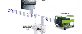
Keep in mind that another type of such a circuit has become widespread; in it, it is customary to install an electrical energy meter between the input circuit breaker and the RCD.
Connection at the input and output lines (in a single-phase network)
With this version of the circuit, the RCD is installed after the input circuit breaker and also on each outgoing line.
The most important condition for this circuit is compliance with selectivity, that is, at the moment a current leak appears, there should not be a simultaneous shutdown of the general and group RCDs.
We’ll talk about what selectivity is a little lower.
For example, there was a current leak on one of the outgoing lines. The device that protects this particular group should operate.
If for some reason the RCD does not work, then after a certain time (this is called a time delay) the general RCD at the input will turn off; it, as it were, protects the outgoing one.
The undoubted advantage of such a scheme is that at the moment of damage only the emergency line will be turned off, and the voltage supply will not stop in the rest of the apartment.
The disadvantages of such a scheme are the large dimensions of the distribution panel and the high cost (the RCD is not a cheap thing, and with this option you will need several of them).
The video shows a comparison of several connection schemes:
You can save a little and omit the single-phase RCD at the input in this scheme, that is, install only group devices on the outgoing lines. Many electricians generally consider an introductory RCD to be a waste of money, because each line already has its own protection. But as we said above, it is a kind of safety net in case the group device fails. Therefore, it all depends on your financial capabilities. If you have money, install a circuit with an RCD at the input. If it’s so expensive, install only outgoing devices, that will also be great. Many people do not install an RCD at all, preferring to save money on their own safety.
Drawing up a diagram
Modern power supply systems involve the use of a three-wire cable, where one wire is a phase, and the rest are ground and zero. Given the growing power of devices, it is also necessary to divide them into groups, which allows to increase the service life of the wiring. Guided by these principles, we proceed to drawing up a diagram of the shield.
Advice! It is better to entrust the design of the panel and electrical wiring of the apartment to a professional so as not to miss important details. Otherwise, you will have to redo the repair.
It is mandatory to install a protection device on the input cable, which will protect the internal network from overvoltage. Then they install a voltage relay to control surges in the network, after which they proceed to the installation of groups and individual lines. It is worth noting that for powerful devices, in addition to switches, additional RCDs or differential circuit breakers are used. Such organization of the home electrical network is not only safe, but also convenient. If necessary, you can turn off the machine and turn off the washing machine. You can also turn off the RCD and de-energize all consumers included in the global group.
Installation of the device in a single-phase network
There is nothing complicated here. The phase and neutral conductors (“L” and “N”) coming after the input circuit breaker must be connected to the input contacts of the RCD.
From the output contact, the phase conductor (“L”) is distributed to the circuit breakers of outgoing consumers. The neutral conductor (“N”) from the output of the RCD is connected to the neutral busbar. And from there the working zeros disperse to consumers.
Don't forget about the protective conductor! A grounding bar must be installed. From it, protective conductors (“PE”) disperse among consumer groups.
The connection algorithm looks like this:
- De-energize the workplace by turning off the input circuit breaker for the apartment. Check the absence of voltage at its output contacts using an indicator screwdriver.
- Secure the device to the DIN rail. It has special perforated holes into which the rear RCD latches are inserted.
- Now you need to correctly connect the RCD and the machine. Decide on the circuit whether you will have a residual current device on a separate line or after the meter. The upper and lower contacts for the phase and neutral wires are marked on the RCD body; perform the appropriate switching actions. According to the diagram, the input is connected to the RCD from above, and the load is already connected from below.
- After completing all the switching, you need to apply voltage and check the operation of the RCD by pressing the “TEST” button. A leakage current will be simulated, the device should react and turn off.
Is it normal that the RCD is connected to the meter and the machines, respectively?
Hello. I have a one-room apartment. All the electrical work was done before me. I read the forum.. I looked at how everything is assembled in my panel.. Questions and doubts arose. Is it normal that the RCD is connected to the meter and the machines, respectively? How to determine whether the cable to which the block is connected is valid? “earth” is earth (and why is it blue)? I would like to get advice on what needs to be replaced, additionally installed, corrected? Thank you.
House with electric stoves? Looks like yes
Blue color is actually a working zero.
The RCD up to the meter is normal, this is the introductory RCD (fire protection) - at 100 mA. It also replaces the packet to relieve voltage from the meter
There are 4 wires in the riser.
So everything is OK. Millions of people have this type of wiring, sleep well. In houses with electric stoves, ZERO does not burn out.
It’s hard to see, but it looks like there’s still five wires here, the blue wire is PE
azus6 wrote: In houses with electric stoves, ZERO does not burn out.
I have twice already in 4 years
Thank you. But “this is an introductory RCD (fire protection)” at 30 mA. Is this normal? Are no more RCDs required?
Matros wrote: Are any more RCDs required?
Firstly, this is not an RCD, but a differential. Secondly, fire protection from 100mA. Thirdly, your earth is yellow.
30 ma for input is not good.
It will often turn off spontaneously. Fireproof ones are 100 and 300 mA.
lev125 wrote: Thirdly, your land is yellow.
Mine might be yellow. but connected to a BLUE cable..(you can see it in the photo)..
lev125 wrote: Firstly, this is not an RCD, but a differential.
Of course, I’m not an electrician, but I can read.. On the case it says “Residual current device.. RCD” (also visible in the photo).
Judging by the picture, there are generally 7 main conductors in the riser. Judging by the wiring, the blue main conductor is PE (again, damn it, color-blind main conductors were purchased), and the conductor on which the top nut is N. Essentially, this is a five-wire. It is unclear from the photographs why two more “spare” main conductors are needed and where they go.
Matros wrote: .. On the body it is written “Residual current device.. RCD”
There is also a lot of things written on the fence. In this case, it is (already discontinued) VAD 1 from Energomera - a two-pole circuit breaker, mechanically controlled from an electronic RCD type A. According to today's generally accepted terminology, this is an electronic automatic circuit breaker.
azus6 wrote: It will often turn off spontaneously.
Maybe it will, maybe not. Practice will show.
Matros wrote: How to determine whether the cable to which the ground block is connected is really ground
Measure the current flowing through it with a current clamp. It’s called a “main PE conductor” and according to the rules it should be yellow-green, but the developer seems to have messed up the color marking rules.
Matros wrote: Are any more RCDs required?
Adding a mechanical RCD from a decent consumer could be helpful. How does this VAD react to the “test” button? Do VAD triggers during normal operation of consumers?
What is a three-phase network and how to connect an RCD in it?
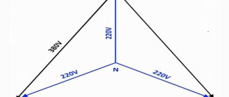
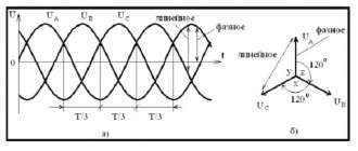
In a three-phase network there is also a phase and a zero, only there are three phase conductors (“L 1”, “L 2”, “L 3”). The voltage between any of the phases is 380 V, between phase and zero – 220 V. It is very important in such an electrical network to distribute the load evenly between the phases. If one phase is loaded more and the other less, a imbalance will occur, and as a result, an emergency situation.
Similar to a single-phase network, a three-phase network can consist of four or five conductors. In the first case, there are three phase wires and a neutral wire; in the second, a protective grounding conductor is also added.
An example of assembling a three-phase electrical panel in the video:
Installation of an RCD in a three-phase network is carried out in exactly the same way as in a single-phase network: you can install it only at the input or connect one more residual current device to each outgoing group of consumers. An equally appropriate option is when an electricity meter is connected between the input circuit breaker and the RCD.
In apartments you are unlikely to find a three-phase network anywhere, but for private houses a voltage of 380 V may be required to connect pumps, motors, and machines.
RCDs and circuit breakers on a three-phase switchboard
Let us examine in detail a not entirely standard circuit assembled on a three-phase distribution panel.
It contains:
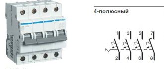
- three-phase input circuit breakers - 3 pcs.;
- three-phase residual current device - 1 pc.;
- single-phase RCDs - 2 pcs.;
- single-pole single-phase circuit breakers - 4 pcs.
From the first input circuit breaker, voltage is supplied to the second three-phase circuit breaker through the upper terminals. From here, one phase goes to the first single-phase RCD, and the second to the next.
The voltage from the second input circuit breaker is supplied to a three-phase RCD, the lower terminals of which are connected to a three-phase load. This protective device protects against leakage currents, and the second input circuit breaker protects against short circuits.
Single-phase RCDs installed on the panel are two-pole, and automatic machines are single-pole. For the protective device to function correctly, it is necessary that the working zeros after it are not connected anywhere else. Therefore, after each RCD, a zero bus is installed here.
When the machines are not one-pole, but two-pole, then there is no need to install a separate zero bus. If two zero buses are combined, false positives will occur.
Each of the single-pole RCDs is designed for two circuit breakers (1-3, 2-4). A load is connected to the lower terminals of the machines.
The common ground bus is installed separately. Three phases enter the input circuit breaker: L1, L2, L3 and the working neutral wire.
The zero is connected to the common zero, and from it goes to all the RCDs. Then it goes to the load: from the first device - to three-phase, and from the next single-phase - each to its own bus.
In a three-phase network, electrical quantities are vector, therefore their total value is determined not by the algebraic, but by the vector sum of these quantities
Although this distribution panel has a three-phase input, the wire is not divided into PEN and PE, because five-wire input. Three phases, zero and grounding come to the shield.
Selectivity
RCDs with a selectivity function differ from ordinary ones in that they have a certain time delay. They are used when several devices are mounted in one distribution panel at once. In order for the entire chain to work smoothly, it is imperative to adjust the response time settings. According to this characteristic, there are two types of RCDs: “G” and “S”.
Visually about the RCD selectivity in the video:
An ordinary RCD is triggered 0.02-0.03 s after detecting a current leak, a type “G” device is triggered after 0.06-0.08 s. RCD type “S” has the longest time delay of 0.15-0.5 s.
The protective shutdown device on the outgoing lines is mounted without a time delay, and is installed at the input of type “S” or “G”. As soon as a current leak appears on any consumer line, the group RCD instantly reacts and turns off.
If it is not working properly or for some other reason does not work, then after a specified time the input device will turn off.
Selectivity can be ensured not only by time, but also by current.
Some tips for choosing
And some recommendations on choosing an RCD. If you plan to install one device at the input, then choose high-quality products from well-established manufacturers. These are companies such as:
- "ABB";
- "Legrand"
- Schneider Electric.
Residual current devices from these manufacturers will cost you about 1800-2000 rubles.
If you want to connect several RCDs and circuit breakers in an apartment (for each outgoing branch), then you will either have to spend a lot of money or choose devices that are a little cheaper. In case of small financial possibilities, opt for RCD or “EKF”, they are slightly inferior in terms of quality and reliability, but also cost much less (about 600-700 rubles).
We have given several options for how to connect an RCD. Choose the one that is most suitable for you, depending on where you live (in an apartment or a private house), what kind of network you have (single-phase or three-phase). Well, decide how many devices you will supply (one at the input or for each consumer group), based on your financial situation.
Electrical panel project
Scheme for assembling and connecting the electrical panel in the apartment: Using the connection diagram, you can begin installing the electrical panel. If it is planned to install consumers with a power of up to 2.5 kW, then it is desirable to install separate protection.
Next, we move on to dividing all connection points into several groups.
One machine serves the lighting group, the second - sockets, and the third - the washing machine.
A single-phase network branch goes to outbuildings. Similar RCDs are installed on entire groups of consumers.
See also: Corrugated pipe for a bath
New articles by email
Here, using an example, I will tell you how to read the electrical diagram of a panel, give several examples, and at the end of the article I will give a link to download 19 electrical circuits of the panels. You will also need the diagram when accepting work as an electrician. This is approximately what a properly organized cable entry into an electrical panel looks like: power supply on the left, residential network lines on the right. Installation of an electrical panel in an apartment If you are assembling a panel or moving it, then first of all you need to decide on the installation location.
They break the circuit if an overcurrent or short circuit is detected, protecting the wiring and connected equipment from damage. In order not to make a mistake when purchasing a switchboard housing based on the number of modules, you need to draw up a wiring diagram.
It is very important to decide in advance on the number of machines and select an electrical panel of appropriate dimensions. TN-C is an old type of power supply, the wiring in the apartment includes a two-core copper or aluminum cable, the cable in the switchboard combines zero and ground. Below are group cables feeding certain groups, indicating the cable brand and its cross-section depending on the load. Each of these machines is responsible for a specific part of the circuit. The RCD is turned on as follows: the phase is connected to the inputs of the machines, and the neutral wire is connected to the neutral common wire.
The principle is the same as that of a water supply system - one riser per entrance, from which there are branches to each user. Is this necessary? Option 3 As I wrote above, all groups of sockets must have protection against current leakage, that is, they must be protected using an RCD. Electrical wiring diagram in the apartment