Which wire to choose for the ground line
If the electrical wiring is done from scratch, then you should not run a separate cable for the grounding loop - it can be included in the common conductor, as an additional conductor to the existing phase and neutral. This means that any cable in the apartment must be three-wire: “phase”, “zero” and “ground”.
A separate paragraph in the PUE is devoted to PE conductors or grounding wires.
And paragraph 1.7.121. clearly states that:
- The ground wire can be laid together with the phase conductor.
- It is possible to use both insulated and non-insulated PE conductor.
Third subparagraph 1.7.121
. states that the grounding conductor can be laid permanently, as many electrical installation companies now do, which is quite justified.
Operating principle of the grounding system
The operating principle of the grounding system is extremely simple. What is the damaging (destructive) force of electric current? It all starts with the fact that in one place, when special conditions are created, a very large number of negatively charged particles - electrons - accumulate. But since everything in nature strives for balance, this excess of particles rushes to where there are not enough of them. It doesn't sound very scary, but when a stream of electrons rushes towards the ground from electrified clouds, these tiny particles manage to heat the layers of the atmosphere to a million degrees Celsius.
Inventors have learned to channel this flow into a peaceful channel - through electrical wires. Passing through the wire, electrons cause it to heat up and sometimes, due to overheating, it, the wire, begins to glow brightly. The flow of electrons also creates an electromagnetic field that drives the rotors of powerful motors.
But machines sometimes break down and a flow of electrons makes its way through any object that conducts electric current, sometimes the human body becomes a similar conductor. Thus, grounding of buildings is intended to provide charged particles, electrons, figuratively speaking, an alternative path - a more convenient, with less resistance, path to the exit. As a result, most of the electrons pass through the protective ground loop and reduce the amount of current directed to the human body.
Installation and correct calculation of grounding and lightning protection is a necessary condition for the safety of those living in the house.
What is grounding used for and how does it work?
Any electrician, even a freshman, will tell you that grounding is a specially created connection of working electrical equipment (a point or a network node) with some grounding device.
Ground bus.
The latter can be either specially mounted structures and devices, or soil. Both are equally effective, but are used in different cases.
The grounding device and working cables are selected depending on the purpose of the grounding. There are only a couple of main types:
- working (or functional),
- protective.
A process is called functional when it is directly necessary for the correct and proper operation of the equipment.
Protective, in turn, is grounding, which leads to safe operation of devices for humans. This type is not used directly all the time (unlike the previous one), but only in situations of breakdowns, failure or when the device is struck by lightning.
Note that protective grounding is often used to reduce the amount of electromagnetic interference.
In apartments and houses, protective grounding is carried out. For domestic purposes, an inexpensive grounding conductor is usually used - a single-core cable or part of a multi-core cable. The main component of the wire is always copper, but the cross-section varies. The main question that worries home craftsmen and inexperienced electricians is what cross-section should the grounding wire be? Let's try to answer.
1.7.121
As PE
-conductors in electrical installations with voltage up to 1 kV can be used:
1) specially provided conductors:
cores of multi-core cables;
insulated or non-insulated wires in a common sheath with phase wires;
permanently laid insulated or non-insulated conductors;
2) open conductive parts of electrical installations:
aluminum cable sheaths;
steel pipes for electrical wiring;
metal shells and supporting structures of busbars and complete prefabricated devices.
Metal boxes and trays of electrical wiring can be used as protective conductors, provided that the design of the boxes and trays provides for such use, as indicated in the manufacturer's documentation, and their location excludes the possibility of mechanical damage;
3) some third party conductive parts:
metal building structures of buildings and structures (trusses, columns, etc.);
reinforcement of reinforced concrete building structures of buildings, subject to the requirements of 1.7.122;
metal structures for industrial purposes (crane rails, galleries, platforms, elevator shafts, lifts, elevators, channel frames, etc.).
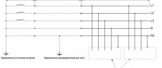
Grounding devices for electrical installations with voltages up to 1 kV in networks with a solidly grounded neutral
1.7.100. In electrical installations with a solidly grounded neutral, the neutral of a three-phase alternating current generator or transformer, the midpoint of a direct current source, one of the terminals of a single-phase current source must be connected to the grounding conductor using a grounding conductor.
An artificial ground electrode designed to ground the neutral, as a rule, should be located near the generator or transformer. For intra-shop substations, it is allowed to place the ground electrode near the wall of the building.
If the foundation of the building in which the substation is located is used as natural grounding, the neutral of the transformer should be grounded by connecting to at least two metal columns or to embedded parts welded to the reinforcement of at least two reinforced concrete foundations.
When built-in substations are located on different floors of a multi-story building, the grounding of the neutral of the transformers of such substations must be carried out using a specially laid grounding conductor. In this case, the grounding conductor must be additionally connected to the building column closest to the transformer, and its resistance is taken into account when determining the spreading resistance of the grounding device to which the transformer neutral is connected.
In all cases, measures must be taken to ensure continuity of the grounding circuit and protect the grounding conductor from mechanical damage.
If a current transformer is installed in the PEN conductor connecting the neutral of a transformer or generator to the PEN bus of a switchgear with voltage up to 1 kV, then the grounding conductor should not be connected to the neutral of the transformer or generator directly, but to the PEN conductor, if possible immediately after the transformer current In this case, the division of the PEN conductor into PE and N conductors in the TN-S system must also be carried out behind the current transformer. The current transformer should be placed as close as possible to the neutral terminal of the generator or transformer.
1.7.101. The resistance of the grounding device to which the neutrals of a generator or transformer or the terminals of a single-phase current source are connected, at any time of the year should be no more than 2, 4 and 8 Ohms, respectively, at line voltages of 660, 380 and 220 V of a three-phase current source or 380, 220 and 127 In a single-phase current source. This resistance must be ensured taking into account the use of natural grounding conductors, as well as re-grounding conductors PEN or PE conductor of an overhead line with a voltage of up to 1 kV with a number of outgoing lines of at least two. The resistance of the ground electrode located in close proximity to the neutral of the generator or transformer or the output of a single-phase current source must be no more than 15, 30 and 60 Ohms, respectively, at line voltages of 660, 380 and 220 V of a three-phase current source or 380, 220 and 127 V of a single-phase source current
If the earth resistivity r >100 Ohm×m, it is allowed to increase the specified standards by 0.01r times, but not more than tenfold.
1.7.102. At the ends of overhead lines or branches from them with a length of more than 200 m, as well as at the inputs of overhead lines to electrical installations in which automatic power off is used as a protective measure in case of indirect contact, the PEN conductor must be re-grounded. In this case, first of all, natural grounding devices should be used, for example, underground parts of supports, as well as grounding devices intended for lightning overvoltages (see Chapter 2.4).
The specified repeated groundings are performed if more frequent groundings are not required under the conditions of protection against lightning surges.
Repeated grounding of the PEN conductor in DC networks must be performed using separate artificial grounding conductors, which should not have metal connections to underground pipelines.
Grounding conductors for repeated grounding of the PEN conductor must have dimensions no less than those given in table. 1.7.4.
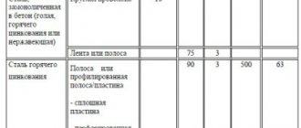
Table 1.7.4
The smallest dimensions of grounding conductors and grounding conductors laid in the ground
| Material | Section profile | Diameter, mm | Cross-sectional area, mm | Wall thickness, mm |
| Black steel | Round: | |||
| for vertical grounding conductors | 16 | — | — | |
| for horizontal grounding conductors | 10 | — | — | |
| Rectangular | — | 100 | 4 | |
| Angular | — | 100 | 4 | |
| Pipe | 32 | — | 3,5 | |
| Galvanized steel | Round: | |||
| for vertical grounding conductors | 12 | — | — | |
| for horizontal grounding conductors | 10 | — | — | |
| Rectangular | — | 75 | 3 | |
| Pipe | 25 | — | 2 | |
| Copper | Round | 12 | — | — |
| Rectangular | — | 50 | 2 | |
| Pipe | 20 | — | 2 | |
| Multi-wire rope | 1,8* | 35 | — |
* Diameter of each wire.
1.7.103. The total resistance to spreading of grounding conductors (including natural ones) of all repeated groundings of the PEN conductor of each power line at any time of the year should be no more than 5, 10 and 20 Ohms, respectively, at line voltages of 660, 380 and 220 V of a three-phase current source or 380, 220 and 127 V single-phase current source. In this case, the spreading resistance of the grounding conductor of each of the repeated groundings should be no more than 15, 30 and 60 Ohms, respectively, at the same voltages.
If the specific resistance of the earth is r >100 Ohm×m, it is allowed to increase the specified standards by 0.01 r times, but not more than tenfold.
Grounding devices for electrical installations with voltages up to 1 kV in networks with an insulated neutral
1.7.104. The resistance of the earthing device used for protective earthing of exposed conductive parts in an IT system must satisfy the following condition:
R ≤ Upr/I,
where R is the resistance of the grounding device, Ohm;
Upr is the touch voltage, the value of which is assumed to be 50 V (see also 1.7.53 );
I is the total ground fault current, A.
As a rule, it is not necessary to accept a grounding device resistance value of less than 4 ohms. A grounding device resistance of up to 10 Ohms is allowed if the above condition is met, and the power of generators or transformers does not exceed 100 kVA, including the total power of generators or transformers operating in parallel.
Grounding devices in areas with high earth resistivity
1.7.105. Grounding devices of electrical installations with voltages above 1 kV with an effectively grounded neutral in areas with high earth resistivity, including in permafrost areas, are recommended to comply with the requirements for touch voltage (see 1.7.91).
In rocky structures, it is allowed to lay horizontal grounding conductors at a shallower depth than required by 1.7.91-1.7.93, but not less than 0.15 m. In addition, it is allowed not to install the vertical grounding conductors required by 1.7.90 at entrances and at entrances.
1.7.106. When constructing artificial grounding systems in areas with high earth resistivity, the following measures are recommended:
1) installation of vertical grounding conductors of increased length, if the resistivity of the earth decreases with depth, and there are no natural deep grounding conductors (for example, wells with metal casing pipes);
2) installation of remote grounding electrodes, if there are places with lower earth resistivity near (up to 2 km) from the electrical installation;
3) laying moist clay soil in trenches around horizontal grounding conductors in rocky structures, followed by compaction and backfilling with crushed stone to the top of the trench;
4) the use of artificial soil treatment in order to reduce its resistivity, if other methods cannot be used or do not give the required effect.
1.7.107. In permafrost areas, in addition to the recommendations given in 1.7.106, you should:
1) place grounding conductors in non-freezing reservoirs and thawed zones;
2) use well casing pipes;
3) in addition to deep grounding conductors, use extended grounding conductors at a depth of about 0.5 m, designed to operate in the summer when the surface layer of the earth thaws;
4) create artificial thawed zones.
1.7.108. In electrical installations with voltages above 1 kV, as well as up to 1 kV with an isolated neutral for earth with a resistivity of more than 500 Ohm×m, if the measures provided for in 1.7.105-1.7.107 do not allow obtaining earthing conductors acceptable for economic reasons, it is allowed to increase the required this chapter, the values of the resistance of grounding devices are 0.002r times, where r is the equivalent resistivity of the earth, Ohm×m. In this case, the increase in the resistance of grounding devices required by this chapter should be no more than tenfold.
Grounding switches
1.7.109. The following can be used as natural grounding electrodes:
1) metal and reinforced concrete structures of buildings and structures that are in contact with the ground, including reinforced concrete foundations of buildings and structures that have protective waterproofing coatings in non-aggressive, slightly aggressive and moderately aggressive environments;
2) metal water pipes laid in the ground;
3) casing pipes of boreholes;
4) metal sheet piles of hydraulic structures, water conduits, embedded parts of valves, etc.;
5) rail tracks of main non-electrified railways and access roads if there is a deliberate arrangement of jumpers between the rails;
6) other metal structures and structures located in the ground;
7) metal shells of armored cables laid in the ground. Cable sheaths can serve as the only grounding conductors when there are at least two cables. Aluminum cable sheaths are not allowed to be used as grounding conductors.
1.7.110. It is not allowed to use pipelines of flammable liquids, flammable or explosive gases and mixtures, and sewerage and central heating pipelines as grounding conductors. The specified restrictions do not exclude the need to connect such pipelines to a grounding device for the purpose of equalizing potentials in accordance with 1.7.82.
Reinforced concrete structures of buildings and structures with prestressed reinforcement should not be used as grounding conductors, however, this restriction does not apply to overhead line supports and outdoor switchgear support structures.
The possibility of using natural grounding conductors based on the density of currents flowing through them, the need to weld reinforcing bars of reinforced concrete foundations and structures, welding anchor bolts of steel columns to reinforcing bars of reinforced concrete foundations, as well as the possibility of using foundations in highly aggressive environments must be determined by calculation.
1.7.111. Artificial grounding conductors can be made of black or galvanized steel or copper.
Artificial grounding conductors should not be painted.
The material and smallest dimensions of grounding conductors must correspond to those given in table. 1.7.4.
1.7.112. The cross-section of horizontal grounding conductors for electrical installations with voltages above 1 kV should be selected according to the condition of thermal resistance at a permissible heating temperature of 400 °C (short-term heating corresponding to the duration of the protection and tripping of the circuit breaker).
If there is a risk of corrosion of grounding devices, one of the following measures should be taken:
increase the cross-sections of grounding conductors and grounding conductors, taking into account their estimated service life;
use galvanized or copper grounding conductors and grounding conductors.
In this case, one should take into account the possible increase in the resistance of grounding devices due to corrosion.
Trenches for horizontal grounding conductors must be filled with homogeneous soil that does not contain crushed stone and construction waste.
Grounding electrodes should not be located (used) in places where the ground is dried out by the heat of pipelines, etc.
Grounding conductors
1.7.113. The cross-sections of grounding conductors in electrical installations with voltages up to 1 kV must comply with the requirements of 1.7.126 for protective conductors.
The smallest cross-sections of grounding conductors laid in the ground must correspond to those given in table. 1.7.4.
Laying bare aluminum conductors in the ground is not permitted.
1.7.116. To carry out measurements of the resistance of the grounding device, it must be possible to disconnect the grounding conductor in a convenient place. In electrical installations with voltages up to 1 kV, such a place, as a rule, is the main grounding bus. Disconnection of the grounding conductor must be possible only with the help of a tool.
1.7.117. The grounding conductor connecting the working (functional) grounding conductor to the main grounding bus in electrical installations with voltages up to 1 kV must have a cross-section of at least: copper - 10 mm2, aluminum - 16 mm2, steel - 75 mm2.
1.7.118. An identification sign must be provided at the points where grounding conductors enter buildings
1.7.126. The smallest cross-sectional areas of protective conductors must comply with table. 1.7.5.
The cross-sectional areas are given for the case when the protective conductors are made of the same material as the phase conductors. The cross-sections of protective conductors made of other materials must be equivalent in conductivity to those given.
Table 1.7.5
Smallest cross-sections of protective conductors
| Section of phase conductors, mm2 | Minimum cross-section of protective conductors, mm |
| S ≤ 16 | S |
| 16 < S ≤ 35 | 16 |
| S>35 | S/2 |
We select a cable for grounding.
Before selecting a ground wire, there are several other fundamental issues to consider.
Owners of private houses or country cottages, as well as old apartments built before 1998, have to carry out grounding themselves. Modern houses already have a ready-made grounding system, unlike all old ones. To select the correct section, you need to find out what system exists in the house.
There are only four main ones, according to the Electrical Installation Rules (hereinafter PUE):
- TN-S - grounding is carried out using a separate wire and neutral in an alternating current system;
- TN-C - the “zero” and “ground” cables are combined into one wire, the neutral is separate, most common in houses of the last century;
- TT - direct protective grounding installed on electrical equipment;
- IT - working with the device body through resistance or complete insulation of all current-carrying cables.
Directly on the grounding diagram you should find one of the markings:
- PE - “grounding”,
- PEN - “zero” and “ground” in one cable.
The next important selection factor that will help determine the correct cross-section of the conductor is the type of grounding. Stationary or portable - depending on the purpose. For ordinary household grounding, a sufficient and stationary type, which in turn allows both multi-wire and single-wire multi-core cables.
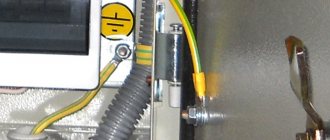
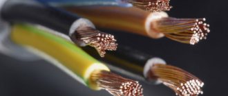
The wire must be made in yellow-green insulation color, according to the PUE.
When we have decided on the type, material of the cable and the type of system, we move on to the main step - selecting the cable cross-section.
Requirements for grounding, protective conductors and system conductors
The technological characteristics of grounding conductors must correspond to the location of their installation, the method of connection, and the materials from which the wires are made. In addition to special requirements, general rules also apply to such products. Only then will any of them reduce the value of the electric current to 0.
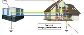
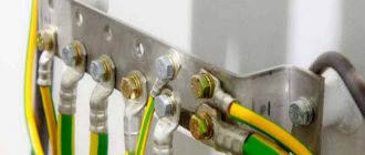
The connection of protective systems is carried out to a common point for any electrical equipment - to a solidly grounded neutral according to 5 main circuits. When connecting a ground electrode, zero potential is created using a neutral wire, which is usually designated by the letter symbol N. The protective neutral cable has its own designation - PE.
After potential equalization, the voltage in the wiring will be the same as during a short circuit. Therefore, for the cross-section of the grounding conductors, the same diameter is selected as that of the phase cable. The marking of the wires used can be selected taking into account the values accepted by GOST from ready-made tables located in the PES applications. All cables used can only be of high quality manufacturing and with the required technological characteristics.
To carry out separate calculations of the cross-section of the grounding conductor, a formula is used that indicates the short circuit indicators, the type of wire used and the technology for its installation. When calculating the parameters of the protection system being created, it should be taken into account that the resistance passing through it cannot exceed 4 Ohms. A more secure connection is created when using the screw connection method. The neutral cable should be painted blue, and the ground wire should be yellow.
The principle of construction and purpose of protective grounding
In simple terms, protective grounding is formed as follows. The ground wire is connected to a non-current-carrying metal part.
At the next stage, the “ground” connected to the equipment is combined, and then goes through a separate wire or busbar to the grounding device.
In the event of a voltage breakdown on a metal body and a person touches it, the potential goes through the ground and not through the body. Due to the low resistance, protection and RCDs operate faster.
In comparison, the R of a ground loop is only 4 ohms or less, and that of a human is more than 1000 ohms. According to Ohm's law, we know that current always follows the path of least resistance.
Thus, protective grounding is designed to solve the following problems:
- reducing the potential difference between the grounded device and other objects and protecting human life;
- draining current into the ground and increasing its values to trigger protective devices (RCDs, automatic devices).
Therefore, when laying a conductor for grounding, it is important to ensure the presence of protective devices. The latter must quickly respond to leakage or high currents by cutting off the damaged area. The sooner this happens, the better.
Why is building grounding necessary?
Our distant ancestors encountered only manifestations of atmospheric electricity. But even then people knew how dangerous lightning strikes could be and called them “the wrath of the gods.” Archaeological excavations have shown that already in those distant times people understood some of the principles of the operation of atmospheric electricity and tried to create primitive protection systems. These finds were long copper rods, towering above buildings, with the opposite end immersed in the ground.
However, with the development of human society and technology, electricity has firmly entered our everyday life. And then the question arose about protecting humans from the damaging factors of electric current, but this time not atmospheric, but “domestic” generated by machines built by man himself. The solution turned out to be on the surface.
Indeed, grounding buildings is almost an exact copy of the design of a lightning rod. From the dangerous zone, the current is diverted into the ground using a feeder - a metal rod, wire, cable.
Using grounding, they protect electrical units, home networks, household and industrial equipment. In cases where a fire occurs at power supply facilities, the pumps of fire trucks and even the hand-held nozzles (fire nozzles) with which firefighters extinguish the fire must be grounded using special devices.
Calculation of the cross-section of the grounding conductor
Many master electricians do not really delve into the essence of the issue and always purchase a cable with cores of the same cross-section. As a result, the “ground” wire does not differ from the phase or working “zero”. But the PUE provides for the smallest dimensions of grounding conductors and is listed in the form of formulas in a separate table.
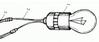
Figure 2: Ground wires with pre-crimped terminal
Basic formulas for determining the smallest cross-section of a PE conductor:
- With phase cross-section S ≤ 16 mm2, cross-section of PE conductor: S.
- With phase cross-section 16 < S ≤ 35, cross-section of PE conductor: 16.
- With phase cross-section S > 35, cross-section of PE conductor: S/2.
It should be immediately clarified that such calculations are performed only at serious industrial enterprises, and when laying electrical wiring in scrap areas or apartments, they are very often neglected.
Ground wire color and connection features
To avoid confusion, it is important to understand what designations need to be provided for such wires.
Today the following types of markings are used:
- PE - 0 protective wires and bars, colored in the form of intertwined yellow-green shades.
- N - 0th wires, indicated in blue (neutral).
- PEN - combination of zero and ground. The main part is blue, at the edges there is a combination of yellow and green colors.
In our case, a designation with the corresponding color design (yellow and green) is used. It is designated in the same way in a three-core wire.
If you don’t have a wire with the required color on hand, you can use regular yellow and green electrical tape. All that is required is to make marks on the ends of the wire.
Grounding (PE) is brought out and connected to the grounding bus, body or metal panel door. The neutral wire (N) is connected to the neutral busbar.
Read more about grounding and zeroing https://elektrikexpert.ru/zazemlenie-i-zanulenie.html, what is the difference between them.
Main brands of grounding wires.
Grounding cable.
NYM cable
The conductors, or rather their shell, are painted in accordance with PUE standards, and there are copper conductors inside. It has an additional intermediate sheath, which increases the level of safety even with long-term use of the cable. Easy to use and install, suitable for voltages up to 660 Volts with a frequency of 50 hertz.
VVg cable
Cores with copper wire of the first and second class of twist have a characteristic color, with “zero” being blue and “ground” being yellow-green. The insulation and outer sheath are made of polyvinyl chloride, due to which the cable itself prevents combustion.
Wire PV-6
Copper, stranded, sheathed in transparent PVC. The conductor is clearly visible under such a sheath, making it easy to monitor the integrity of the entire length of the wire. Very flexible, can be easily exposed to temperatures ranging from -40 to +55 degrees Celsius.
Wire ESUY
Typical application is for system short circuit protection. Withstands enormous loads, found in work on railways and in distribution blocks. Resistant to temperatures and bending, has protection from physical and chemical influences.
Wire PV-3
Many thin soft strands of copper wire are woven under a single layer of polyvinyl chloride. The release is possible in eleven colors, but the yellow-green version is traditionally used for grounding.
A special feature of the shell is increased fragility under improper production or storage conditions. Pay attention to the fresh cut: there should be no breaks. Otherwise, it is not recommended to use the cable.
How to use all this? For grounding an ordinary average apartment, both multi-core VVG and single-wire NYM are equally suitable. Sometimes, in order to save money, PPV wire is used, without a characteristic color. This is fraught with problems when repairing or replacing wiring in the apartment. Often German ESUY, flexible single-core wires, are used for apartments.
As you can see, understanding which wire is needed for grounding is a rather difficult task, but doable. It is enough to carefully understand the issue and familiarize yourself with several provisions from the rules for electrical installations.
How is a house grounding loop installed?
Experts recommend doing this work during the warmer months. Cause:
- ease of work;
- no problems when measuring loop resistance.
Metal structures are located underground. For private houses, a triangle-shaped outline is optimal. A ground electrode laid in the ground of the appropriate configuration:
- has an impressive area;
- is able to provide a small resistance (electrical) to the circuit.
Installation of grounding conductors begins with choosing a suitable location. The depth of the structure is chosen below the soil freezing mark - 0.7-1 m. A trench towards the power shield is dug from one of the corners of the triangle.
Lightning protection of private houses involves driving electrodes into the vertices of the triangle (they act as grounding conductors). A steel corner with a side width of 50 mm is optimal for these purposes. The rods are driven into the ground. When the soil is dense, it becomes necessary to drill wells. The electrodes should protrude above ground level.
Lightning protection of buildings is achieved as a result of the formation of a circuit. In practice, a 40*5 mm steel strip is used for these purposes. It must be welded to the rods. The strip from the metal triangle is led to the power cabinet. There it is attached to the cable using a bolt. This fastener should be welded to the strip.
Grounding buildings requires loop testing. For these purposes, a diagnostic device is used - an ohmmeter. Mandatory requirement: the value of the grounding indicator is less than regulated. If necessary, additional metal rods are driven into the ground.
The final stage of the work is filling the trench with earth. The soil must be homogeneous (the presence of crushed stone and construction waste in it is not allowed). When operating the circuit in dry weather, the soil (at its location) is watered. Goal: reducing structural resistance.
Marking
For a better understanding, let us raise the issue of marking the insulation of the conductors used.
The following symbols can be used in the wire name:
- A - aluminum core (in the absence of a letter - copper);
- AC - presence of lead braid;
- AA - stranded wire with an aluminum core and a braid of the same material;
- B - corrosion protection, made of double-layer steel;
- G - without shell;
- Bn - protection from moisture and resistance to fire;
- NP - non-flammable material;
- R - rubber shell;
- B - polyvinyl chloride shell;
- K - control cable, etc.
You must pay attention to the above markings when choosing a wire for grounding in relation to its cross-section (this was mentioned above).
Types
Grounding of buildings and electrical installations of various voltages is constructed according to one of three types: ring, deep or foundation. The choice of the type of circuit and materials for the ground electrode for a particular building is made taking into account its size and purpose, installation capabilities and limitations, the degree of saturation with electrical equipment and a number of other reasons. If necessary, several grounding systems can be interconnected (taking into account the risk of corrosion). Any building grounding must be connected to a potential equalization bus.
Photo of wires for grounding
Did you like the article? Share