Not to be confused with Effective antenna length.
| This article need additional quotes for verification . |
| Part of the series on |
| Antennas |
Common types
|
Components
|
Systems
|
Safety and Regulation
|
Radiation sources/regions
|
Characteristics
|
Methods
|
|
In telecommunications and electrical engineering, electrical length
(or
phase length
) refers to the length of an electrical conductor in terms of the phase shift introduced by transmission along that conductor[1] at a certain frequency.
Use of the term
Depending on the specific context, the term "electrical length" is used, rather than simply physical length, to include one or more of the following three concepts:
- When you are interested in the number of wavelengths, or phase, involved in the passage of a wave through a segment of a transmission line in particular, you can simply specify this electrical length without specifying the physical length, frequency, or speed factor. In this case, the electrical length is usually expressed as N
wavelength or as phase φ, expressed in degrees or radians. Thus, in a microstrip design it is possible to specify a shorted stub length of 60° phase, which will correspond to different physical lengths when applied to different frequencies. Or one might consider a 2-meter section of coaxial cable with a quarter-wavelength (90°) electrical length at 37.5 MHz and ask what its electrical length becomes when the circuit operates at a different frequency. - Due to the speed coefficient of a particular transmission line, for example, the time it takes a signal to travel through a cable of a certain length is equal to the time it takes to travel through a longer
distance when traveling at the speed of light. Thus, a pulse sent along a 2-meter section of coaxial cable (which has a speed factor of 67%) will reach the end of the coaxial cable at the same time as the same pulse that will arrive at the end of a bare wire 3 meters long (through which it travels at the speed of light) , and a 2 meter section of coaxial cable can be said to have an electrical length of 3 meters, or an electrical length of 1/2 wavelength at 50 MHz (since a 50 MHz radio wave has a wavelength of 6 meters). - Since resonant antennas are usually specified in terms of the electrical length of their conductors (e.g., a half-wave
dipole), achieving such an electrical length broadly equates to electrical resonance, i.e., purely resistive impedance at the antenna input, as is generally desired.
For example, an antenna that has been made too long will have inductive reactance, which can be corrected by physically shortening the antenna. Based on this understanding, common jargon in the antenna trade refers to achieving resonance (reactance suppression) at antenna terminals as electrically shortening
an antenna that is too long (or
electrically lengthening
an antenna that is too short) when the electrical matching network (or antenna tuner) has completed this task without
physically
changing the length of the antenna. Although the terminology is very imprecise, this usage is widespread, especially as applied to the use of a loading coil at the bottom of a short monopole (vertical, or whip antenna) to "electrically lengthen" it and achieve electrical resonance visible through the loading coil.
Electrical characteristics of symmetrical cables: transmission parameters
where P0 and Px are the signal powers at the beginning of the line and at an arbitrary point X, respectively. If, for example, Px = 0.1 P0, then a = 10 dB.
Any two-wire communication line is a low-pass filter. Therefore, link attenuation is an increasing function of frequency.
Line attenuation also increases with temperature, which should be taken into account during design. Digital communication systems are especially sensitive to changes in attenuation: with an increase in line attenuation by just 1 dB, the error rate of a digital signal can increase by one to two orders of magnitude.
It should be noted that the term Attenuation refers to the so-called intrinsic attenuation, which is characteristic of a homogeneous line. This line is the construction length of the cable with the same design and electrical parameters along its entire length. Any real communication line (for example, a subscriber or connecting line) is a collection of many cable lengths connected in series, and they may have different design and electrical parameters. Therefore, in practice, the communication line is heterogeneous, and the main inhomogeneities are concentrated at the joints of building cable lengths or are caused by cable defects due to deviations in the process of their production, installation and operation.
In electrical communication theory, the attenuation of such a line is called Insertion Loss (IL). Unlike the intrinsic attenuation, the introduced attenuation is not strictly dependent on its length. The degree of connection is determined by the degree of homogeneity of a particular line.
Any communication line introduces signal delay. The signal will be transmitted without distortion if the delay time is the same over the entire operating frequency range.
Distortion of the delay time in a line can occur due to sudden changes in its input resistance at the junction or excessive bending of the cable, which causes reflected signals. These effects are especially noticeable at high frequencies, where they can be caused by the pair not being twisted where the connector is installed. Therefore, such connectors are not used in SCS, starting from Category 5. The requirements for uniformity of cable characteristics along its entire length, compliance with the impedance of twisted pairs of the cable and connectors, methods of laying and fastening, as well as the quality of installation of cable terminations are becoming increasingly strict.
In the case of using xDSL technologies on subscriber lines of a telephone network, the heterogeneity of the cables that make them up also plays a negative role. In addition to the types of inhomogeneities mentioned above, they can be caused by parallel taps, the presence of which is explained by the fact that when a subscriber refuses to use telephone services, the corresponding subscriber pair of the distribution cable is not always disconnected.
Along with delay time distortions, the delay time itself (Propagation Delay) has a very significant impact on the quality of signal transmission. It is critically important, for example, when transmitting signals simultaneously in one direction along several parallel pairs of one cable. This transmission method (also called inverse multiplexing) is used, in particular, for spatial separation of signals, when a high-speed signal is transmitted in parallel over several symmetrical pairs. It should be taken into account that a large spread of delay time (Propagation Delay Skew) of cable pairs can disrupt the correct order of restoration of the original high-speed signal at reception.
The degree of heterogeneity of the communication line is assessed using the Return Loss (RL) parameter, which is most often translated as “return loss”. It is perhaps more appropriate to call this parameter reflection attenuation or mismatch attenuation, since it is a logarithmic measure of the reflection coefficient at the junction of two cable sections:
Phase length
The first use of the term "electrical length" suggests a sine wave of some frequency or at least a narrowband waveform centered around some frequency .
.
The sine wave will repeat with a period T
=
1⁄f
.
The frequency w
will correspond to a specific wavelength λ along a specific conductor.
For conductors (such as bare wire or air-filled coax) that transmit signals at the speed of light c
, the wavelength is given by λ =
c
⁄
f
.
The distance L
along this conductor corresponds to
N
wavelengths, where
N
;
= L
⁄λ.
The figure on the right shows wave N
= 1.5 wavelengths.
The crest of the wave at the beginning of the graph, moving to the right, will appear at the end after time 1.5. T
.
The electrical length
of this segment is "1.5 wavelengths" or, expressed as a phase angle, "540°" (or 3π radians), where
N
wavelengths correspond to φ = 360°•
N
(or φ = 2π•
N
radians ). In radio frequency applications where delay is introduced due to a transmission line, the phase shift φ is often important, so defining a design in terms of phase or electrical length allows that design to be adapted to an arbitrary frequency using the wavelength λ applied to that frequency.
Speed factor
In a transmission line, the signal travels at a speed controlled by the effective capacitance and inductance per unit length of the transmission line. Some transmission lines consist only of bare wires, in which case their signals travel at the speed of light. c
.
More often, the signal travels at a reduced speed κ c
, where κ is
the speed coefficient
, a number less than 1 that represents the ratio of this speed to the speed of light.[2][3]
Most transmission lines contain a dielectric material (insulator) that fills some or all of the space between the conductors. Relative dielectric constant or dielectric constant
The use of this material increases the distributed capacitance in the cable, which reduces the speed factor below unity.
It is also possible for κ to decrease due to the relative permeability ( μ r { displaystyle mu _ { text { r ))} ) of this material, which increases the distributed inductance, but this almost never happens. Now, if we fill the space with a dielectric with a relative permeability ϵ r { displaystyle epsilon _ { text {r))} , then the speed of a plane electromagnetic wave decreases by the speed coefficient: κ = v p c = 1 ϵ r μ r ≈ 1 ϵ r { displaystyle kappa = { frac {v_{p}} {c}} = { frac {1} { sqrt { epsilon _ { text {r}} mu _ { text {r}} }}} approximately { frac {1} { sqrt { epsilon _ { text {r}}}}}} .
This reduced speed factor can also be applied to the propagation of signals along wires immersed in a large space filled with this dielectric. However, when only part of the space around the conductors is filled with this dielectric, the wave speed decreases less. Part of the electromagnetic wave surrounding each conductor “feels” the action of the dielectric, and part is in free space. Then we can determine the effective relative dielectric constant
ϵ eff { displaystyle epsilon _ { text {eff}}} which then predicts the speed coefficient according to
κ = 1 ϵ eff { displaystyle kappa = { frac {1} { sqrt { epsilon _{ text {eff}}}}}}
ϵ eff { displaystyle epsilon _ { text {eff))} is calculated as the weighted average of the relative permittivity of free space (1) and the dielectric:
ϵ eff = ( 1 − F ) + F ϵ r { displaystyle epsilon _ { text {eff)) = (1-F) + F epsilon _ { text {r))}
where is the duty cycle
F expresses the effective fraction of space affected by the dielectric.
In the case of a coaxial cable, where the entire volume between the inner conductor and the screen is filled with a dielectric, the fill factor is equal to unity, since the electromagnetic wave is limited to this area. In other types of cable, such as double lead, the duty cycle can be much lower. In any case, any cable designed for radio frequency will have a speed factor (as well as a characteristic impedance) specified by the manufacturer. In the case of coaxial cable, where F = 1, the speed factor is determined solely by the type of dielectric used, as specified. Here.
For example, a typical speed factor for coaxial cable is 0.66, which corresponds to a dielectric constant of 2.25. Let's say we want to send a 30 MHz signal down a short section of such cable and delay it by a quarter wave (90°). In free space this frequency corresponds to a wavelength λ0= 10 m, so for a delay of 0.25 λ an electrical length
2.5 m. Using a speed factor of 0.66, we obtain
a physical
cable length of 1.67 m.
The speed factor also applies to antennas in cases where the antenna conductors are (partially) surrounded by dielectric. This especially applies to microstrip antennas such as the patch antenna. Microstrip waves are mainly affected by the dielectric of the circuit board underneath them, but also by the air above them (due to edge effects). Thus, their speed coefficients do not depend directly on the dielectric constant of the printed circuit board material, but on the effective
dielectric constant ϵ eff { displaystyle epsilon _ { text { eff))} which is often specified for the PCB material (or can be calculated). Note that the fill factor, and therefore ϵ eff { displaystyle epsilon _ { text { eff }}}, is somewhat dependent on the width of the trace compared to the thickness of the board.
Summary
- A connection is considered a transmission line when its length is at least a quarter of the wavelength of the signal.
- Coaxial cables are commonly used as transmission lines, although traces on printed circuit boards also serve this purpose. The two standard transmission lines on printed circuit boards are the single-ended microstrip and the balanced stripline.
- PCB connections are usually short, and therefore they do not show transmission line behavior until signal frequencies approach 1 GHz.
- The ratio of voltage to current in a transmission line is called characteristic impedance. It depends on the physical properties of the cable, although it is not affected by cable length, and for idealized (i.e. lossless) lines it is purely resistive.
Original article:
- What Is a Transmission Line?
Antennas
Although there are certain broadband antenna designs, many antennas are classified as resonant and operate by design at a specific frequency. This is especially true for broadcast stations and communications systems that are limited to a single frequency or narrow band. This includes dipole and monopole antennas and all designs based on them (Yagi, dipole or monopole arrays, folded dipole, etc.). Besides the directive gain of beam antennas suffering from the design frequency, the antenna feed point impedance is very sensitive to frequency shift. Especially for transmission, the antenna is often designed to operate at a resonant frequency. At the resonant frequency, this impedance is by definition a pure resistance which matches that of the characteristic impedance of the transmission line and the output (or input) impedance of the transmitter (or receiver). At frequencies far from the resonant frequency, the impedance includes some reactance (capacitance or inductance). Perhaps an antenna tuner should be used to cancel this reactance (and change the resistance to match the transmission line), however this is often avoided as an additional complication (and needs to be controlled at the antenna side of the transmission line).
The resonance condition in a monopole antenna for the element must be an odd multiple of a quarter of the wavelength, λ
/ 4. In a dipole antenna, both driven conductors must be of such length that the total length of the dipole is
(2N + 1) λ
/2.
The electrical length of an antenna element is usually different from its physical length.[ need a better source
][4][5][6]For example, increasing the diameter of the conductor or the presence of metal objects nearby will reduce the speed of the waves in the element, increasing the electrical length.[7][8]
An antenna whose length is less than its resonant length is described as " electrically short
“,[9] and exhibits capacitance.
Similarly, an antenna whose length exceeds its resonant length is described as " electrically long
" and exhibits inductive reactance.
Change in electrical length under load
Load coil in a mobile phone antenna mounted on the roof of a car.
The coil allows the antenna to be shorter than a quarter wavelength and still remain resonant. The effective electrical length of an antenna can be changed without changing its physical length by adding reactance (inductance or capacitance) in series with it.[10] This is called lumped impedance matching
or
download
.
For example, a monopole antenna such as a metal rod with one end will be resonant when its electrical length is equal to a quarter of the wavelength, λ
/ 4 frequencies used.
If the antenna is shorter than a quarter wavelength, the feedpoint impedance will include capacitance; this causes reflections on the feed and mismatch at the transmitter or receiver, even if the resistive component of the impedance is correct. To neutralize capacitive reactance, an inductance called a loading coil is inserted between the feeder and the antenna terminal. Selecting an inductance with the same reactance as the (negative) capacitive reactance seen at the antenna terminal cancels that capacitance and the antenna system
(antenna and coil) will be resonant again. The power line has purely resistive impedance. Because an antenna that was too short now appears to be resonant, adding a loading coil is sometimes called "electrically extending" the antenna.
Similarly, the feedpoint impedance of a monopole antenna is greater than λ
/4 (or a dipole with arms longer than
λ
/4) will include inductive reactance. A capacitor in series with the antenna can neutralize this reactance to make it resonant, which can be called "electrical shortening" of the antenna.
Inductive loads are widely used to reduce the length of whip antennas in portable radios such as walkie-talkies and short-wave antennas on automobiles to meet physical requirements.
A vertical antenna that can have any desired height: approximately less than half the wavelength of the frequency at which the antenna operates. These antennas can work as transmitting or receiving antennas.
Advantages
Electrical extension allows shorter antennas to be created. Used in particular for antennas for VLF, long-wave and medium-wave transmitters. Because these radio waves range in length from several hundred meters to many kilometers, radiator masts of the required height are economically impossible to implement. It is also widely used for whip antennas on portable devices such as walkie-talkies to allow antennas much shorter than the standard quarter wavelength to be used. The most widely used example is the rubber duck antenna.
Flaws
Electrical extension reduces the antenna's throughput unless other phase control measures are taken. An electrically extended antenna is less efficient than an equivalent full-size antenna.
Technical implementation
There are two possibilities for implementing electrical extension.
- inclusion of induction coils in series with an antenna
- switching metal surfaces, known as roof capacitance, at the ends of the antennas, which form capacitors to the globe.
Often both indicators are combined. Coils connected in series sometimes need to be placed in the middle of the antenna structure. The cabin installed at a height of 150 meters on the Blosenbergturm in Böromünster is such a design in which an extension coil is installed to power the top of the tower (a ring capacitor is additionally installed on the roof of the Blosenbergturm on the roof)
Statement
In the transmitting antennas of transmitters operating at frequencies below the long-wave radio broadcasting range, electrical extension is always used. It is often used in broadcast antennas of long-wave radio broadcasting stations. However, electrical extension is widely used for NDB transmit antennas because they use antennas whose height is significantly less than a quarter of the emitted wavelength.
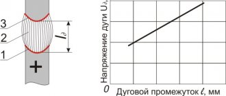
- On the left are characteristics constructed on the basis of experimentally obtained data on coordinates with a logarithmic abscissa. On the right is an antenna with increased effective inductance between the two points, in accordance with the well-known operation of shunt-tuned circuits, adjusted slightly off-resonance.
Calculation and selection of wire cross-section in various ways
Understanding all the parameters and processes occurring with electricity is the key to choosing the right cable. This article explains step by step the relationships between physical quantities that affect the reliable operation of the power grid and its safe operation.
It is known that all metals have free electrons that move in the presence of an applied electrical voltage, creating an electric current. When they hit atoms, they lose energy, which turns into heat. The greater the current, the denser the flow of particles, and the smaller the cross section of the conductor through which they pass, the more crowded they are; collisions are more frequent, useful energy is lost, and the release of useless and often dangerous heat increases.
Avalanche of heat
Important! As the temperature rises, the resistivity increases and heat release increases, which leads to an avalanche-like process of rapid heating with catastrophic consequences.
There are complex formulas that calculate heat balance, using the melting coefficient and thermal coefficient of resistance of the conductor, to determine the cross-sectional area of the conductor.
But, in everyday life, ready-made tables are used, which take into account the possibility of cable overheating in hidden wiring - in this case, for the same current and power values, the cross-section is prescribed to be large for the cable in poorly ventilated and thermally insulated places, so that the heating does not exceed the permissible limit.
Solution in practice
It is carried out using special tables and PUE standards, according to which the cable cross-section is selected. The cross-sectional value of the conductor is selected in several ways:
- Calculation of wire cross-section by power;
- Selecting a current wire;
- If there is already a wire, but of unknown cross-section.
Selection by power
Each electrical appliance indicates its rated power. By summing up the power of electrical appliances that are planned to be connected to the designed electrical network at the same time, get a certain number and, using the table, select the appropriate cross-section of a copper or aluminum cable, choosing the appropriate power value.
First of all, it is necessary to take into account the expected load on the electrical wiring that we are going to lay. If there are several electrical appliances on one section of the electrical network, then to calculate the expected load we add up all their capacities. After calculating this indicator, we analyze the method in which we will lay the electrical networks (open or closed), as well as the impact of what temperature conditions will be exerted on the wires.
It is also very important to calculate the correct cable cross-section because errors in calculations will lead to power losses in the wires. If this is not so significant for household appliances, then on an industrial scale this can lead to quite serious waste.
So, take a piece of paper and a pen, write down all the electrical appliances in your apartment and add up their power:
where P1 is the power of, for example, a kettle of 1.5 kW, P2 is the power of a vacuum cleaner of 1.6 kW, etc.
After all the powers have been added up, it is necessary to multiply the total power by the simultaneity factor K=0.8. This coefficient shows that during a certain period of time all electrical appliances in the apartment will work, but not for a long time, but for a short period of time, this must be taken into account, because if you choose a wire cross-section based only on power, you will choose a larger wire cross-section, and this may turn out to be significantly more expensive.
So, we get:
After calculating the total power, select the wire cross-section (copper or aluminum) in table 1:
Table 1 - Selection of wire cross-section by power
Important ! If in the future you are going to increase the load, then you must increase the wire cross-section in advance; this remark applies to all methods of determining the wire cross-section.
Current selection
In Table 2 you can find the correspondence between cross sections and rated current. Selection based on this parameter is considered more accurate. It is necessary to look at the passports and labels of electrical appliances; the rated power is usually indicated, and then follow the same procedures as in the method described above.
Next, using the formula, we determine the current that acts maximum in the line and based on this we select the wire cross-section (the formula is applicable for a single-phase 220 V network):
where Ptot. — total power of electrical appliances (W).
It is possible to measure the current with an ammeter for each consumer individually with your own hands and then simply sum the current.
To do this, the tester is connected to an open circuit - in practice, you can take a piece of network cable with a plug, connect one core to the socket terminal, and feed the other to the measuring device. Connect the other ammeter probe to a free terminal of the socket, and turn on existing household appliances one by one, in different operating modes, checking the parameters declared by the manufacturers.
If you have a three-phase network, you need to find the current using this formula:
After we have summed up the currents of electrical appliances, we select the conductor cross-section from the table:
Table 2 Relationship between current and conductor cross-section
One more point, if your three-phase network contains electric motors, then the current of this motor is determined by the formula:
where - P is the engine power, n is the engine efficiency (available on the engine tag), COS f is the power factor (also look at the tag).
And lastly, in a three-phase network we sum up the calculated motor currents and the calculated currents of electrical appliances and select the conductor cross-section from Table 2.
One more thing to consider is cable routing. It can be open or closed, and accordingly the current loads will vary, so when choosing the wire cross-section, pay attention to this. In Table 2 you can analyze this point
The wire is already there
In the opposite situation, when there is a cable, but the markings are not visible, you need to find out its rated current and power; to do this, measure the diameter of the wire with a caliper or micrometer. You can get by with a ruler, if the core is flexible enough, wind it around a thin rod, measure the length of the resulting spiral, divide by the number of turns - the result will correspond to the diameter.
Using the formula, we calculate the cross-sectional area of the conductor:
where π- 3.14, D is the diameter of the conductor, you can take a caliper and measure the diameter (mm)
Using the cross-section selection method from Table 1, you can find out for what power the existing cable is suitable.
It is better to choose the cable cross-section with a margin. It is prohibited to operate a cable wound into a coil due to its inductive reactance.
Installation of aluminum cables should be carried out with extreme caution - frequent bending and straightening produces invisible cracks that reduce the cross-section, resistance increases in this place and spot overheating occurs.
Length check
The conductor length factor l also increases the resistance in the network. It can be neglected at a short distance, but as it increases, the voltage drop across the load will be increasingly noticeable, and it may become lower than the nominal value - 5%.
Let's look in more detail, to avoid this, calculate the cross-sectional area of the entire cable, allowing for a certain value and using it in the formula for determining the resistance:
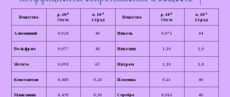
where l is the length of the wire (m), ϱ is the resistivity of the conductor (Ohm*mm²/m) (see Table 2), S is the cross-sectional area of the conductor, determined from the method described above (mm²)
Table 3 - resistivity of metals:
Next, using Ohm's law, we find the voltage drop:
where I is the total current in your network (A), R is the calculated resistance (Ohm).
And lastly, we determine network losses. We divide the calculated voltage drop by the network voltage and multiply by 100%.
If the obtained value exceeds 5% of the network voltage, the cable cross-section must be increased according to table 1.
Recommendations
- Ron Schmitt, Electromagnetism Explained [electronic resource]: A guide to wireless/RF, EMC, and high-speed electronics.
- Carr, Joseph J. (1997). Microwave and wireless technologies
. Newnes. paragraph 51. ISBN 0750697075. - Amlaner, Charles J. Jr. (March 1979). "Design of antennas for use in radio telemetry." Handbook of Biotelemetry and Radio Tracking: Proceedings of the International Conference on Telemetry and Radio Tracking in Biology and Medicine, Oxford, 20–22 March 1979
. Elsevier. p. 260. ISBN 9781483189314. Retrieved November 23, 2013. - Weick, Martin (1997). Standard Dictionary of Fiber Optics
. Springer Science & Business Media. p. 270. ISBN 0412122413. - "Electrical length". Federal Standard 1037C, Glossary of Telecommunications Terms
. National Telecommunications and Information Administrator, US Government Department of Commerce. 1996. Retrieved November 23, 2014. External link in | publisher = (help) - Helfrick, Albert D. (2012). Electrical Spectrum and Network Analyzers: A Practical Approach
. Academic press. paragraph 192. ISBN 978-0080918679. - Lewis, Jeff (2013). Newnes Handbook of Communication Technologies
. Elsevier. paragraph 46. ISBN 978-1483101026. - Carr, Joseph J. (September 11, 2001). Antenna Tool Kit
. 53: (Oxford: Boston Newnes. p. 288. ISBN 9780080493886 .CS1 maint: location (communication) - Slyusar V.I. 60 years of the theory of electrically small-sized antennas .// Proceedings of the 6th International Conference on Antenna Theory and Technology, September 17-21, 2007, Sevastopol, Ukraine. — Page 116 - 118. [1]
- Howard, R. Stephen; Vaughan, Harvey D. (September 1998). NEETS (Navy Electrical and Electronics Training Series) Module 10 - Introduction to Wave Propagation, Transmission Lines and Antennas (NAVEDTRA 14182)
(PDF). US Navy Naval Education and Training Center. pp. 4.17–4.18.
- Terman, Frederick Emmons (1943). Radio Engineer's Handbook
. McGraw-Hill. item 773. - Kraus, John D. (1988). Antennas
(PDF) (2nd ed.). McGraw-Hill. item 413. ISBN 0-07-035422-7. - Balanis, Constantine A. (1997). Antenna theory
. John Wiley and Sons. p.151. ISBN 0-471-59268-4.
further reading
- A. Nickle, US Patent 2125804, " Antenna
". (Filed May 25, 1934; issued August 2, 1938). - William W. Brown, US Patent 2,059,186, " Antenna Structure
" (Filed May 25, 1934; published October 27, 1936). - Robert B. Dome, US Patent 2101674, " Antenna
". (Filed May 25, 1934; issued December 7, 1937). - Slyusar V.I. 60 years of the theory of electrically small-sized antennas .// Proceedings of the 6th International Conference on Antenna Theory and Technology, September 17-21, 2007, Sevastopol, Ukraine. — Page 116 - 118. [2]