Content
- 1 Introduction
- 2 Conductors and resistors
- 3 Ohm's Law
- 4 Relationship with resistivity and conductivity
- 5 Resistance measurement
- 6 Typical resistances
- 7 Static and differential resistance
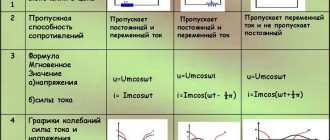
- 8 AC circuits 8.1 Impedance and tolerance
- 8.2 Frequency dependence of resistance
- 10.1 Temperature dependence
Electrical current, electrical resistance and conductivity
2>
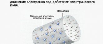
Electricity. In a substance placed in an electric field, under the influence of field forces, the process of movement of elementary carriers of electricity - electrons or ions - occurs. The movement of these electrically charged particles of matter is called electric current.
The unit of current is the ampere (A). This is a current at which an amount of electricity equal to 1 C passes through the cross-section of the conductor every second.
, [A];
A current is called constant, the value and direction of which at any moment of time remain unchanged. Currents, the value and direction of which do not remain constant, are called variables.
The amount of electricity passing through the cross-section of a conductor during one second is called the magnitude of the current and is denoted by the letter I :
; ; ;
The current in the circuit is measured by an electrical device - an ammeter.
The ammeter is connected in series, that is, the circuit is broken in some place and the resulting ends are connected to the terminals of the device.
In order for current to constantly flow through a conductor, a potential difference is necessary at its ends.
Electrical conductivity. The property of a substance to conduct electric current under the influence of an electric field is called electrical conductivity.
. The electrical conductivity of various substances depends on the concentration of free electrically charged particles. The greater the concentration of these particles, the greater the electrical conductivity of a given substance. All substances, depending on their electrical conductivity, are divided into three groups: conductors, dielectrics (insulating materials) and semiconductors.
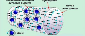
Electrical resistance. When free electrons move in a conductor, they collide along their path with positive ions, atoms and molecules of the substance from which the conductor is made, and transfer part of their energy to them. In this case, the energy of moving electrons as a result of their collision with atoms and molecules is partially released and dissipated in the form of heat, heating the conductor.
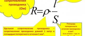
Conductors have electrical resistance - the ability of a conductor to prevent the passage of current.
,
where c is the resistivity of the conductors;
l – conductor length in m;
S – cross-sectional area of the conductor in mm.
Ohm is taken as the unit of resistance.
A conductor has a resistance of 1 ohm, through which a current of 1 A passes with a potential difference at its ends equal to 1 V.
Conductivity. Any conductor can be characterized not only by its resistance, but also by the so-called conductivity - the ability to conduct electric current. Conductivity is the reciprocal of resistance. The unit of conductivity is called siemens (Sm).
The ability of various materials to conduct electric current can be judged by their electrical resistivity (ro) - the resistance of a conductor 1 m long, with a cross section of 1 mm.
| Resistivity ( ) of some materials | |
| Material | |
| Silver | 0,0063 |
| Copper | 0,0175 |
| Aluminum | 0,03 |
| Zinc | 0,063 |
| Steel | 0,12 |
| Nichrome | 0,43 |
| Constantan | 0,5 |
The electrical conductivity of all materials depends on their temperature. In metal conductors, when heated, the range and speed of vibrations of atoms in the crystal lattice of the metal increase, as a result of which the resistance they provide to the flow of electrons also increases. When cooling, the opposite occurs.
For metals, the dependence of resistance on temperature is expressed by the formula:
where - at the initial temperature;
— temperature change;
- temperature coefficient, what fraction corresponds to the change in conductor resistance from the initial value when the temperature changes by 1°C.
As the temperature increases, the resistance of the conductors increases.
2>
Date added: 2017-11-21; views: 2126; ORDER A WORK WRITING
Find out more:
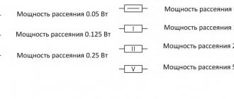
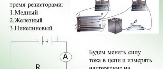
Conductors and resistors
75 ohm resistor as defined by the electronic color code (purple – green – black – gold – red).
An ohmmeter can be used to check this value. Substances in which electricity can flow are called conductors. A piece of conductive material with a specific resistance intended for use in a circuit is called a resistor. Conductors are made from highly conductive materials such as metals, particularly copper and aluminum. On the other hand, resistors are made from a wide variety of materials depending on factors such as the desired resistance, the amount of energy that needs to be dissipated, accuracy, and cost.
Resistivity of various materials
We can talk about resistivity only in the presence of elements that conduct current, since dielectrics have infinite or close to infinite electrical resistance. In contrast, metals are very good conductors of current. You can measure the electrical resistance of a metal conductor using a milliohmmeter, or an even more accurate microohmmeter. The value is measured between their probes applied to the conductor section. They allow you to check circuits, wiring, windings of motors and generators.
Metals vary in their ability to conduct current. The resistivity of various metals is a parameter that characterizes this difference. The data is given at a material temperature of 20 degrees Celsius:
- Silver (ρ = 0.01498 Ohm•mm2/m);
- Aluminum (ρ = 0.027);
Copper (ρ = 0.01721);- Mercury (ρ = 0.94);
- Gold (ρ = 0.023);
- Iron (ρ = 0.1);
- Tungsten (ρ = 0.0551);
- Brass (ρ = 0.026...0.109);
- Bronze (ρ = 0.095);
- Steel (ρ = 0.103…0.14);
- An alloy of nickel, manganese, iron and chromium - nichrome (ρ = 1.051...1.398).
The parameter ρ shows what resistance a meter conductor with a cross section of 1 mm2 will have. The higher this value, the greater the electrical resistance of the desired wire of a certain length. The smallest ρ, as can be seen from the list, is silver; the resistance of one meter of this material will be equal to only 0.015 Ohms, but this is too expensive a metal to use on an industrial scale. Next comes copper, which is much more common in nature (not a precious metal, but a non-ferrous metal). Therefore, copper wiring is very common.
Ohm's law
Main article: Ohm's law
The current-voltage characteristics of four devices: two are resistors, a diode, and a battery.
The horizontal axis is voltage drop, the vertical axis is Current. Ohm's law holds when the graph is a straight line through the origin. Consequently, two resistors are ohmic
, but there is no diode and battery.
For many materials the current I
through a material, proportional to the voltage
V
applied across it:
I ∝ V { Displaystyle I propto V }
over a wide range of voltages and currents. Therefore, the resistance and conductivity of objects or electronic components made from these materials are constant. This relationship is called Ohm's Law, and materials that obey it are called ohmic
materials. Examples of ohmic components are wires and resistors. The current-voltage graph of an ohmic device consists of a straight line through the origin with a positive slope.
Other components and materials used in electronics do not obey Ohm's law; current is not proportional to voltage, so resistance depends on voltage and current through them. They are called nonlinear
or
non-ohmic
. Examples include diodes and fluorescent lamps. The current-voltage curve of an ohmless device is a curved line.
Electrical resistance, conductivity and features of these concepts
In the meaning of the concept, the electrical resistance of a conductor is the state of the body, the environment, in which it converts volumes of electrical energy to thermal energy during the passage of electrical charges inside it. To change the current inside the circuit, a rheostat is used, which serves as electrical resistance. The device consists of winding wire on an insulating base. Due to the long conductor with a small cross-section, the current receives effective resistance.
When combining conductors of different materials of the same length and cross-section, the current conductivity will be different. Accordingly, the density and consistency of the product is of paramount importance for the conductor. The indicator may also change due to temperature. For metals, this value increases in direct proportion to the increase in degrees. The exception is some types of alloys, in which the level of resistance remains the same.
The measurement is performed in Ohms. To compare any types of materials for resistance, standard lengths and cross-sectional sizes are used. You can visually study the process of resistance. To do this, just use two ordinary blades for old-style machines, connect them to the power supply using wires and immerse the metal parts in a container of water. Due to the resistance formed in the conductors, the metal plates are heated, and the water gradually boils.
This process can be explained from the point of view of electrical engineering theory as follows. The movement of free electrons inside a conductor occurs simultaneously with the collision of atoms and other electrons along their path. When these elements meet, an interaction occurs, due to which the charged particles leave their energy.
If the resistance level of a conductor increases, the conductivity of electric current decreases. Based on this, the next concept follows—conductivity. This indicator is inversely proportional to resistance, therefore it expresses an indicator of the conductor’s ability to pass electric current. To obtain this value, it is enough to divide one by the resistance. Conductivity is measured using a value called siemens.
By learning the basics of electrical engineering at school, you can learn how to correctly apply certain materials in practice, which has a beneficial effect on the development of technology . Thus, one of the achievements of electrical engineering was the emergence of such a device as a thyristor drive.
Prepared
Relationship with resistivity and conductivity
Main article: Electrical resistivity and conductivity
A piece of resistive material with electrical contacts on both ends.
The resistance of a given object depends primarily on two factors: what material it is made of and its shape. For a given material, resistance is inversely proportional to cross-sectional area; for example, a thick copper wire has less resistance than an otherwise identical thin copper wire. In addition, for a given material, resistance is proportional to length; for example, a long copper wire has a higher resistance than an otherwise identical short copper wire. The resistance p and conductivity gram of a conductor with a uniform cross-section can therefore be calculated as
р = ρ ℓ А, gram = σ А ℓ. { displaystyle { begin {align} R & = rho { frac { ell} {A}}, [5pt] G & = sigma { frac {A} { ell}}. end {aligned }}}
where ℓ { displaystyle ell } is the length of the conductor, measured in meters (m), A
is the cross-sectional area of the conductor measured in square meters (m2), σ (sigma) is the electrical conductivity measured in Siemens per meter (S m−1) and ρ () is the electrical resistivity (also called
electrical resistivity
) of the material, measured in ohm meters (Ohm m). Resistivity and conductivity are constants of proportionality and therefore depend only on the material from which the wire is made, and not on its geometry. Resistivity and conductance are reciprocal: ρ = 1 / σ { Displaystyle rho = 1 / sigma } . Resistivity is a measure of a material's ability to resist electrical current.
This formula is not accurate because it assumes the current density is completely uniform in the conductor, which is not always true in practical situations. However, this formula still gives a good approximation for long thin conductors such as wires.
Another situation for which this formula is not accurate is with alternating current (AC) because the skin effect prevents current from flowing near the center of the conductor. For this reason, geometric
cross-section is different from
the effective
cross-section in which current actually flows, so the resistance is higher than expected. Likewise, if two conductors next to each other carry alternating current, their resistance increases due to the proximity effect. In industrial frequency networks, these effects are significant for large conductors carrying large currents, such as busbars in an electrical substation,[3] or large power cables carrying more than several hundred amperes.
The resistivity of different materials varies greatly: for example, the conductivity of Teflon is about 1030, several times lower than the conductivity of copper. Roughly speaking, this is because metals have a large number of "delocalized" electrons that are not stuck in any one place, so they can move freely over long distances. In an insulator such as Teflon, each electron is tightly bound to one molecule, so it takes a lot of force to remove it. Semiconductors lie between these two extremes. Read more in the article: Electrical resistivity and conductivity. For electrolyte solutions, see the article: Electrical conductivity (electrolytic).
Resistivity depends on temperature. In semiconductors, resistivity also changes when exposed to light. See below.
Electric current, conductivity, resistance
Electricity
Electric current is the directed movement of electrical charges in a substance
or in a vacuum under the influence of an electric field.
The charge carriers whose movement creates an electric current are:
- in metals - free electrons;
- in liquids and gases - ions.
The current strength is determined by the amount of electricity passing through the cross-section of the conductor per unit time:
where: I - current strength (A)
Q = - amount of electricity (C)
e
- charge of one electron
n - number of electrons
t — time (s)
Current density is the ratio of current to cross-sectional area of the conductor:
where: J - current density (A\mm2 or A\m2)
I - current strength (A) S - cross-sectional area of the conductor).
constant , the magnitude and direction of which are not
change depending on time.
An alternating current is a current that periodically changes in both magnitude and
and by sign.
A person cannot directly observe an electric current; the presence of a current is judged by the phenomena accompanying it. Effects of current: thermal (light), chemical,
electrodynamic, magnetic.
A person feels a current starting from 5 mA; when it increases to 50 mA, it becomes dangerous for
life. For example: current of incandescent lamps 0.1 - 1 A, electric stove 1.5 - 5 A, average power electric motors 5-25 A, in metallurgical installations 50 kA.
Resistance, conductivity
Electrical resistance is the ability of an electrical circuit element to resist the passage of electric current through it. The nature of the resistance is explained by the collision of charge carriers with the nodes of the crystal lattice of the material, which causes its heating.
Resistance is designated by the letter R,r and is measured in ohms (Ohms). 1 Ohm is equal to the resistance of a conductor with a current of 1 A at a voltage at the ends of the conductor of 1 V.
The element of an electrical circuit designed to utilize its electrical resistance is called a resistor.
The resistor is unregulated. The resistor is adjustable. Adjustable resistor (potentiometer).
The ratio of the electric field strength to the current density in the conductor is a constant value for each material and is called electrical resistivity:
where: - resistivity (Ohm\m)
Ep - field strength (V\m)
J- current density (A\m2)
The total resistance of a conductor or resistor is determined by the formula:
where: R - electrical resistance (Ohm) - resistivity (Ohm\m)
l - conductor length (m)
S - cross-sectional area of the conductor (m2)
The quantitative relationship between current, voltage and resistance is expressed by Ohm’s law for a section of a circuit:
I = U/R
The reciprocal of resistance is called conductivity and is measured in siemens (cm):
g=1\R
The reciprocal of resistivity is called conductivity:
Do you agree with the statements:
1. Electric current is the directed movement of electric charges in a substance or in a vacuum under the influence of an electric field.
2. In liquids and gases, charge carriers are positive and negative ions.
3. Current density is determined by the amount of electricity passing through the cross-section of a conductor per unit time.
4. An electric current is called constant, the magnitude and direction of which changes in
depending on time.
5. The chemical effect of current can be observed in an electrolytic bath.
6. Electric current, starting from a value of 5mA, is dangerous to human life.
7. Electrical resistance is explained by the collision of charge carriers with the nodes of the crystal lattice of the conductor material.
8. The electrical resistivity of a conductor is inversely proportional to the current density in it
9. The greater the length of the conductor, the greater the total resistance.
10. The greater the resistance of this section, the greater the current in a section of the circuit.
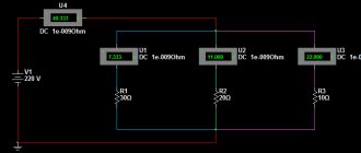
Typical resistances
See also: Electrical resistivity of elements (data page) and Electrical resistivity and conductivity
| Component | Resistance (Ohm) |
| 1 meter of copper wire with a diameter of 1 mm | 0.02[a] |
| 1 km overhead power line ( typical ) | 0.03[5] |
| AA battery ( typical internal resistance ) | 0.1 |
| Incandescent filament ( typical ) | 200–1000[c] |
| The human body | 1000–100,000[d] |
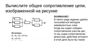
Complex resistance and conductance of the circuit
When calculating a target using a complex method, the concept of complex resistance (conductivity) is introduced.
The complex resistance Z is the ratio of the complex voltage to the complex current caused by this voltage:
Three forms of recording complex resistance are used:
where is the total current resistance; — active resistance; — reactance; - phase difference between voltage and current.
Complex conductivity is the ratio of complex current to complex voltage
Based on expression (1.9)
where is the admittance; -conductance; — reactive conductivity.
The components of resistance and conductivity are related to each other by the following relationships:
Note. The concepts of complex resistance and complex conductance can refer to the entire circuit, to part of the circuit, or to its individual elements.
AC circuits
Impedance and tolerance
Main articles: Electrical impedance and Reception
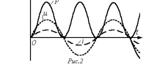
When alternating current flows through a circuit, the relationship between the current and voltage across a circuit element is characterized not only by the ratio of their magnitudes, but also by the difference in their magnitudes. phases. For example, in an ideal resistor, at the moment when the voltage reaches its maximum, the current also reaches its maximum (current and voltage oscillate in phase). But for a capacitor or inductor, the maximum current occurs when the voltage passes through zero and vice versa (current and voltage oscillate 90° out of phase, see image below). Complex numbers are used to track the phase and magnitude of current and voltage:
you ( t ) = r e ( U 0 ⋅ e j ω t ), i ( t ) = r e ( i 0 ⋅ e j ( ω t + φ ) ), Z _ = U _ i _ , Y _ = i _ U _ { Displaystyle u (t) = { mathfrak {Re} } left (U_ {0} cdot e ^ {j omega t} right), quad i (t) = { mathfrak {Re} } left (I_ {0 } cdot e ^ {j ( omega t + varphi)} right), quad { underline {Z}} = { frac { underline {U}} { underline {I }}}, quad { underline {Y}} = { frac { underline {I}} { underline {U}}}} Voltage (red) and current (blue) versus time (horizontal axis) for a capacitor (top) and an inductor (bottom). Since the amplitude of the current and voltage of the sine wave are the same, the absolute value of the resistance is 1 for both the capacitor and the inductor (in any units on the graph). On the other hand, the phase difference between current and voltage is -90° for a capacitor; Therefore the complex phase of the capacitor resistance is -90°. Similarly, the phase difference between current and voltage is +90° for an inductor; therefore, the complex phase of the inductor's impedance is +90°.
Where:
- t
time, - u (t)
and
Eto)
are voltage and current respectively as a function of time, - U0
and
I0
indicate the voltage amplitude of the corresponding current, - ω { displaystyle omega } is the angular frequency of the alternating current,
- φ { displaystyle varphi } displacement angle,
- U
,
I
,
Z
, and
Y
are complex numbers, - Z
is called resistance, - Y
is called tolerance, - Re indicates the real part,
- j = − 1 { displaystyle j = { sqrt {-1))} is the imaginary unit.
Impedance and conductance can be expressed as complex numbers, which can be broken down into real and imaginary parts:
Z _ = R + j X , Y _ = G + j B { displaystyle { underline {Z)) = R + jX, quad { underline {Y)) = G + jB}
where p
and
gram
resistance and conductance respectively,
X
is reactance, and
B
is susceptibility.
For ideal resistors Z
and
Y
are reduced to
p
and
g
respectively, but for alternating current networks containing capacitors and inductors,
X
and
B
are non-zero.
Z _ = 1 / Y _ { displaystyle { underline {Z)) = 1 / { underline {Y))} for AC circuits, as well as R = 1 / G { Displaystyle R = 1 / G} for DC circuits.
Frequency dependence of resistance
A key feature of AC circuits is that resistance and conductance can vary with frequency, a phenomenon known as universal dielectric response.[8] One of the reasons mentioned above is the skin effect (and related proximity effect). Another reason is that the resistance itself may depend on frequency (see Drude model, deep level traps, resonant frequency, Kramers–Kronig relations, etc.)
Resistance and conductivity
Page 1 of 12Next ⇒
The directional movement of electric charges in any conductor is prevented by its molecules and atoms. The quantity characterizing the resistance of an electrical circuit to the passage of electric current is called electrical resistance ( resistance ).
Resistance is designated by the letter R , the unit of measurement is 1 ohm.
To evaluate the electrical properties of a conductor material, resistivity ρ is used - this is the resistance of a conductor with a length of 1 m and a cross-sectional area of 1 mm2.
The resistance of a conductor depends on the material (resistivity), length L and cross-section S , as well as temperature. In metal conductors, the resistance increases with increasing temperature.
Electrical conductivity of a substance (conductivity) is the property of a substance to conduct electric current. This is the reciprocal of resistance, denoted g, measured in siemens, See.
Depending on electrical conductivity, all substances are divided into:
- conductors (conduct electric current well) - metals, solutions of salts, acids, alkalis, coal, graphite. In electrical engineering, aluminum and copper are used to make wires;
- dielectrics (insulators) - practically do not conduct electric current. these include: air, gases, mica, plastics, porcelain, varnishes, enamels, rubber, etc.
- semiconductors - in conductivity they occupy an intermediate position between conductors and dielectrics (silicon, germanium)
Ohm's law
Ohm's law expresses the relationship between emf (voltage), resistance and current.
Ohm's law for a circuit section
The current strength in a section of an electrical circuit is equal to the voltage at the terminals of this section divided by its resistance.
Ohm's law for an electric circuit (closed)
The current strength in a closed circuit is directly proportional to the emf and inversely proportional to the total resistance of the circuit.
The total resistance is equal to the sum of the external R and internal r resistances. Internal resistance is the resistance of the electric current source.
To measure the current in a circuit, an ammeter ; it is connected to the circuit in series (the current circuit is broken and at the point of the break the ends of the wires are connected to the ammeter terminals).
A voltmeter is used to measure voltage ; it is connected in parallel.
Connection diagram for ammeter and voltmeter
Work and power of electric current
Passing through a conductor, electric current does work, which is usually called electrical energy.
Electrical energy ( W ) or work ( A ) performed by electric current is equal to the product of voltage, the current in the circuit and the time it travels.
Work is measured in joules, J , electrical energy is usually measured in kilowatt-hours, kWh , because The joule is a very small unit of measurement.
1 kW*h=3600000 J
Power is the work produced (or consumed) in one second.
Power is designated by the letter P and is measured in watts, W.
are used to measure power , electric meters are used to measure electrical energy .
Thermal effect of current. Joule-Lenz law.
When electric current passes through a conductor, the conductor heats up as a result of collisions with atoms. The amount of heat generated in a conductor during the passage of electric current is determined by the Joule–Lenz law.
The amount of heat generated, Q, is directly proportional to the square of the current, the resistance of the conductor and the time the current passes through the conductor.
The amount of heat is measured in joules, J.
Kirchhoff's law
The sum of currents entering a node is equal to the sum of currents leaving the node.
A node is a point. in which three or more wires are connected.
Terms used in the electric power industry
| Brigade | A group of two or more people, including the work supervisor |
| High-altitude and steeplejack work | Work during which the employee is located at a distance of less than 2 m from unfenced differences in height of 1.3 m or more, if it is impossible to install fences, the work must be performed using a safety belt and a safety rope. Work performed at a height of more than 5 m from the ground surface, ceiling or working flooring on which work is carried out directly from structures or equipment during their installation or repair, while the main means of protecting the worker from falling is a safety belt |
| Overhead power line | A device for transmitting electricity through wires located in the open air and attached using insulators and fittings to supports or brackets and racks on engineering structures (bridges, overpasses, etc.). The beginning and end of the overhead power transmission line are taken to be linear portals or linear inputs of the switchgear, and for branches - a branch support and a linear portal or linear input of the switchgear |
| Overhead line under induced voltage | Overhead lines and overhead lines that run along the entire length or in separate sections near existing overhead lines or near the contact network of an electrified AC railway and on the disconnected wires of which, with different grounding schemes and at the highest operating current of the influencing overhead lines, a voltage of more than 25 V is induced |
| Secondary circuits (secondary connections) | A set of rows of clamps, electrical wires and cables connecting instruments and control devices, circuits, electrical automation, blocking, measurement, relay protection, control and alarm |
| Grounding | Intentional electrical connection of any point in an electrical installation system or equipment to a grounding device |
| Protective grounding | Grounding parts of an electrical installation to ensure electrical safety |
| Electric field influence zone | Space in which the electric field strength exceeds 5 kV/m |
| Magnetic field influence zone | A space in which the magnetic field strength exceeds 80 A/m |
| Safety sign (poster) | A sign intended to warn a person about a possible danger, prohibition or prescription of certain actions, as well as for information about the location of objects, the use of which is associated with the elimination or reduction of the consequences of exposure to hazardous and (or) harmful production factors. |
| cable line | A line for transmitting electricity or its individual impulses, consisting of one or more parallel cables with connecting, locking and end couplings (terminals) and fasteners, and for oil-filled cable lines, in addition, with feeding devices and an oil pressure alarm system |
| Switching device | An electrical device designed for switching an electrical circuit and removing voltage from a part of an electrical installation (switch, load switch, separator, disconnector, circuit breaker, circuit breaker, package switch, fuse, etc.) |
| Lifting machine | Cyclic technical device for lifting and moving loads |
| Mechanisms | Hydraulic lifts, telescopic towers, excavators, tractors, forklifts, drilling and crane machines, mechanically driven retractable ladders, etc. |
| Mechanical lock | Key lock with removable handle |
| Work permit (work order) | A task for the performance of work, drawn up on a special form of the established form and defining the content, place of work, time of its beginning and end, conditions for safe performance, composition of the team and workers responsible for the safe performance of work |
| Operational maintenance of electrical installations | A set of works to: maintain the required operating mode of the electrical installation; production of switchings, equipment inspections; preparation for repairs (preparation of the workplace, admission); technical maintenance of equipment provided for by job and production instructions of operating personnel |
| Inspection | Visual inspection of electrical equipment, buildings and structures, electrical installations |
| Responsible for electrical equipment | An employee from among the administrative and technical personnel who is entrusted with the responsibility for organizing the safe maintenance of electrical installations in accordance with current rules and regulatory technical documents |
| Occupational Safety and Health | A system for preserving the life and health of workers during work, which includes legal, socio-economic, organizational and technical, sanitary and hygienic, treatment and preventive, rehabilitation and other measures |
| Security zone of overhead power lines and overhead communication lines | 1. Zone along the overhead line in the form of land and air space, limited by vertical planes spaced on both sides of the line from the outermost wires with their non-deviated position at a distance, m: for overhead lines with voltage up to 1 kV and overhead lines - 2 for overhead lines 1-20 kV -10 for 35 kV overhead lines - 15 for 110 kV overhead lines - 20 for 150, 220 kV overhead lines - 25 for 330, 500, 400 kV overhead lines - 30 for 750 kV overhead lines - 40 for 1150 kV overhead lines - 55 2. Zone along overhead line transitions through reservoirs (rivers, canals, lakes, etc.) in the form of air space above water, the surface of reservoirs, limited by vertical planes spaced on both sides of the line from the outermost wires when their position is not disconnected for navigable reservoirs at a distance of 100 m, for non-navigable reservoirs - at a distance , provided for the establishment of security zones along overhead lines passing on land |
| Security zone of cable power lines and cable communication lines | 1. A plot of land along underground cable lines, limited by vertical planes spaced on both sides of the line from the outer cables at a distance of 1 m for cable lines and 2 m for cable lines, and for cable lines with voltages up to 1000 V, passing in cities under sidewalks, at a distance of 1. 0 m and 0.6 m, respectively, towards the roadway of the street and the opposite side 2. Part of the water space from the water surface to the bottom along the underwater cable lines and cable lines, limited by vertical planes spaced on both sides of the lines from the outer cables at a distance of 100 m. |
| Administrative and technical staff | Managers and specialists who are entrusted with the responsibility for organizing technical and operational maintenance, carrying out repair, installation and commissioning work in electrical installations |
| Operational staff | Personnel performing operational management and maintenance of electrical installations (inspection, operational switching, preparation of the workplace, admission and supervision of workers, performance of work in the order of routine operation) |
| Operational and repair personnel | Repair personnel specially trained and prepared for operational maintenance of the electrical installations assigned to them within the approved scope |
| Repair personnel | Personnel providing maintenance and repair, installation, adjustment and testing of electrical equipment |
| Electrical personnel | Administrative-technical, operational, operational-repair, maintenance personnel who organize and carry out installation, adjustment, maintenance, repair, control of the operating mode of electrical installations |
| Electrotechnological personnel | Personnel whose main component in the technological process they control is electrical energy (for example, electric welding, electric arc furnaces, electrolysis, etc.), who use manual electric machines, portable power tools and lamps in their work, and other workers for whom the job description or the labor safety instructions establish knowledge of these Rules (where II or higher electrical safety group is required) |
| Preparation of the workplace | Carrying out technical measures before starting work to prevent workers from being exposed to hazardous production factors in the workplace |
| Working without removing voltage on or near live parts (live) | Work performed by touching live parts that are energized (active or live), or at a distance from these live parts that is less than permissible |
| Stress relief work | Work when the voltage is removed from the live parts of the electrical installation on which work will be carried out by disconnecting the switching devices, disconnecting the buses, cables, wires and measures are taken to prevent the supply of voltage to the live parts at the place of work |
| Workplace when performing work in an electrical installation | An area of an electrical installation where personnel are allowed to perform work as assigned, ordered, or in the course of routine operation |
| Order | A task for the performance of work, defining its content, place, time, safety measures (if required) and the workers entrusted with its implementation, indicating the electrical safety group |
| Switchgear | An electrical installation used for receiving and distributing electricity and containing switching devices, busbars and connecting busbars, auxiliary devices (compressor, battery, etc.), as well as protection devices, automation and measuring instruments |
| Open switchgear | Switchgear where all or major equipment is located outdoors |
| Closed switchgear | Switchgear whose equipment is located in a building |
| Complete switchgear | Switchgear consisting of fully or partially closed cabinets or blocks with built-in devices, protection and electrical automation devices, supplied assembled or fully prepared for assembly. |
| Maintenance | A set of operations or an operation to maintain the functionality or serviceability of a product when used for its intended purpose, waiting, storage and transportation |
| Current-carrying part | Part of an electrical installation that is normally energized |
| Non-current carrying part | Part of an electrical installation that may be energized during emergency operation, for example, the body of an electrical machine |
| Electrical substation | Electrical installation designed for the conversion and distribution of electrical energy |
| Electrical network | A set of substations, switchgears and electrical lines connecting them located on the territory of a district, settlement, and consumers of electrical energy |
| Electrical protective agent | A protective device designed to ensure electrical safety |
| Electrical installation | A set of machines, apparatus, lines and auxiliary equipment (together with the structures and premises in which they are installed) intended for the production, transformation, transformation, transmission, distribution of electrical energy and its conversion into another type of energy |
| Electrical installation open or external | An electrical installation that is not protected by the building from atmospheric influences. Electrical installations protected only by canopies, mesh fences, etc. are considered external. |
| Electrical installation closed or internal | Electrical installation located inside a building that protects it from atmospheric influences |
| The electrical installation is operational | An electrical installation or part thereof that is energized or to which voltage can be applied by switching on switching devices |
| Electrical installation with a simple visual diagram | Switchgear with voltages above 1000 V with a single sectionalized or non-sectional bus system that does not have a bypass bus system, all overhead lines and cable lines, all electrical installations with voltages up to 1000 V |
1Next ⇒
Recommended pages:
Energy dissipation and Joule heating
Main article: Joule heating
Passing a current through a resistive material causes heating in a phenomenon called Joule heating. This picture shows a cartridge heater, heated by Joule heating, glowing red hot.
Resistors (and other elements with resistance) prevent the passage of electrical current; therefore, electrical energy is required to push current through the resistance. This electrical energy is dissipated, heating the resistor in the process. This is called Joule heating
(after James Prescott Joule), also called
ohmic heating
or
resistive heating
.
Dissipation of electrical energy is often undesirable, especially in the case of transmission losses in power lines. High voltage transmission helps reduce losses by reducing the current for a given power.
On the other hand, Joule heating is sometimes useful, such as in electric stoves and other electric heaters (also called resistance heaters
). Another example: incandescent light bulbs rely on Joule heating: the filament is heated to such a high temperature that it glows with white-hot thermal radiation (also called incandescence).
Formula for Joule heating:
P = I 2 R { displaystyle P = I ^ {2} R}
where n
is the power (energy per unit time) converted from electrical energy to thermal energy,
p is
the resistance, and
i is
the current through the resistor.
Dependence of resistance on other conditions
Temperature dependence
Main article: Electrical resistivity and conductivity § Temperature dependence
Near room temperature, the resistivity of metals generally increases with increasing temperature, while the resistivity of semiconductors generally decreases with increasing temperature. The resistivity of insulators and electrolytes may increase or decrease depending on the system. For a detailed description of the behavior and explanation, see Electrical Resistivity and Conductivity.
As a result, the resistance of wires, resistors and other components often changes with temperature. This effect can be undesirable and cause electronic circuit failure at extreme temperatures. However, in some cases the effect is put to good use. When the temperature-dependent resistance of a component is used purposefully, the component is called a resistance thermometer or thermistor. (A resistance thermometer is made of metal, usually platinum, while a thermistor is made of ceramic or polymer.)
Resistance thermometers and thermistors are commonly used in two ways. Firstly, they can be used as thermometers: By measuring the resistance, you can determine the ambient temperature. Secondly, they can be used in conjunction with Joule heating (also called self-heating): if a large current is passed through a resistor, the temperature of the resistor rises and therefore its resistance changes. Therefore, these components can be used in a circuit protection role similar to fuses, or for feedback in circuits, or for many other purposes. Typically, self-heating can turn a resistor into a nonlinear and hysteretic circuit element. See Thermistor#Self-heating effects for more details.
If temperature T
not much different, a linear approximation is usually used:
R ( T ) = R 0 [ 1 + α ( T − T 0 ) ] { Displaystyle R ( T ) = R_ {0} [ 1+ alpha ( T-T_{0}) ]}
where α { displaystyle alpha } is the temperature coefficient of resistance
, T 0 { displaystyle T_{0)} is a fixed reference temperature (usually room), and R 0 { displaystyle R_{0)} resistance at temperature T 0 { displaystyle T_{0)} . The parameter α {displaystyle alpha} is an empirical parameter selected based on measurement data. Since the linear approximation is only an approximation, α{displaystyle alpha} differs for different reference temperatures. For this reason, it is common to specify the temperature at which α { displaystyle alpha } was measured with a suffix such as α 15 { displaystyle alpha _ {15)} , and this relationship only holds over a range of temperatures around the reference.[9]
The temperature coefficient α { displaystyle alpha } is typically + 3 × 10⁻³ K−1 to + 6 × 10⁻³ K−1 for metals near room temperature. For semiconductors and dielectrics it is usually negative and has very different magnitudes.[e]
Strain Dependence
Main article: Load cell
Just as the resistance of a conductor depends on temperature, the resistance of a conductor depends on voltage. By placing a conductor under tension (a form of stress that results in deformation in the form of stretching of the conductor), the length of the stretched section of the conductor increases and its cross-sectional area decreases. Both of these effects contribute to an increase in the resistance of the stressed section of the conductor. Under compression (deformation in the opposite direction), the resistance of the deformed section of the conductor decreases. See the discussion on strain gauges for details of devices created to exploit this effect.
Dependence on illumination
Main articles: Photoresistor and Photoconductivity
Some resistors, especially those made from semiconductors, exhibit photoconductivity
, which means their resistance changes when light shines on them.
That's why they are called photoresistors
(or
light-dependent resistors
). This is a common type of light detector.
Electrical resistance and conductivity. units of measurement
The electrical resistance of a conductor, which is denoted by the Latin letter r, is the property of a body or medium to convert electrical energy into thermal energy when an electric current passes through it.
Variable electrical resistance that serves to change the current in a circuit is called a rheostat. In general, a rheostat is made of a wire of one resistance or another, wound on an insulating base. The slider or rheostat lever is placed in a certain position, as a result of which the required resistance is introduced into the circuit.
A long conductor with a small cross-section creates a large resistance to current. Short conductors with a large cross-section offer little resistance to current.
If you take two conductors from different materials, but the same length and cross-section, then the conductors will conduct current differently. This shows that the resistance of a conductor depends on the material of the conductor itself.
The temperature of the conductor also affects its resistance. As temperature increases, the resistance of metals increases, and the resistance of liquids and coal decreases. Only some special metal alloys (manganin, constantan, nickel and others) hardly change their resistance with increasing temperature.
So, we see that the electrical resistance of a conductor depends on: 1) the length of the conductor, 2) the cross-section of the conductor, 3) the material of the conductor, 4) the temperature of the conductor.
The unit of resistance is one ohm. Om is often represented by the Greek capital letter Ω (omega). Therefore, instead of writing “The resistance of the conductor is 15 ohms,” you can simply write: r = 15 Ω. 1,000 Ohms is called 1 kiloohm (1kOhm, or 1kΩ), 1,000,000 Ohms is called 1 megaohm (1mOhm, or 1MΩ).
When comparing the resistance of conductors from different materials, it is necessary to take a certain length and cross-section for each sample. Then we will be able to judge which material conducts electric current better or worse.
Electrical conductivity is the ability of a material to pass electric current through itself. Electrical conductivity, or otherwise electrical conductivity, is the reciprocal of resistance. Conductivity is designated by the letter G.
G = 1/R
In the SI system, electrical conductivity is measured in siemens (1 Sm = 1 Ohm⁻¹). In the Gaussian system and in the SGSE, staticsiemens is used, and the SGSM uses absiemens.
Conductivity, along with resistance, plays a big role in electrical engineering and other technical sciences. Its physical meaning is intuitively clear from its hydraulic counterpart - everyone understands that a wide hose has lower resistance to water flow, and, accordingly, it passes water better than a thin one. The same goes for electrical conductivity—matter with lower resistance conducts electricity better.
The unit of electrical conductivity is named after the famous German engineer, inventor, scientist and industrialist - founder of Siemens - Ernst Werner von Siemens. By the way, it was he who proposed the mercury unit of resistance, which is somewhat different from the modern ohm. Siemens defined the unit of resistance as the resistance of a column of mercury 100 cm high with a cross-section of 1 mm² at a temperature of 0 ° C.
Superconductivity
Main article: Superconductivity
Superconductors are materials that have exactly zero resistance and infinite conductivity because they can have V = 0 and I 0. This also means that there is no Joule heating, or in other words, no electrical dissipation. Therefore, if a superconducting wire is turned into a closed circuit, current will flow through it indefinitely. Superconductors require cooling to temperatures of about 4 K with liquid helium for most metal superconductors such as niobium-tin alloys, or cooling to temperatures of about 77 K with liquid nitrogen for expensive, brittle and delicate ceramic high-temperature superconductors. However, there are many technological applications of superconductivity, including superconducting magnets.
Basic laws of current flow in linear electrical circuits
Ohm's Law: Defines the relationship between current, voltage and resistance of a passive element (branch, section, circuit). The real form of the law is applicable only for resistance:
Ohm's law in complex form is valid for any passive element:
Kirchhoff's first law: Determines the balance of currents in any node of an electrical circuit. It can be represented as a real
or in complex form
where is the number of branches connected at a given node.
Kirchhoff's second law. Determines the voltage balance in any closed circuit circuit:
where is the number of passive elements in a closed circuit: is the number of sources included in this circuit.
Relationship between sinusoidal current and voltage in passive elements
In resistance, the real form of recording the relationship between current and voltage is determined by Ohm’s law:
In complex form (images) are defined by the expressions:
In resistance, current and voltage are always in phase, i.e.
In inductance, voltage and current are related by the relations:
Let us write these expressions in complex form:
where is the complex inductance resistance; — inductive reactance;
- complex conductivity of inductance; - inductive conductivity.
From formulas (1.20) and (1.21) it is clear that the current in the inductance lags in phase from the applied voltage by an angle .
In a capacitance, voltage and current are related by the following relationships:
In complex form, expressions (1.22) take the form:
where is the complex resistance of the capacitance; — capacitance; — complex conductivity of the capacitance; — capacitive conductivity.
From formulas (1.22) and (1.23) it is clear that the current in the capacitor is ahead of the applied voltage in phase by an angle .
Current and voltage diagrams
For greater clarity, time and vector diagrams are used when analyzing processes and calculating penalties.
A time diagram is a graph of instantaneous values of currents and voltages on a coordinate plane along the real time axis (Fig. 1.4). The initial phase reports from zero of the sine wave (or from the maximum of the cosine wave) to the origin. The initial phase is positive if the counting direction coincides with the direction of the time axis.
The phase shift of voltage and current is measured in the direction from zero voltage to zero current. If this direction coincides with the direction of the time axis, then the phase shift is positive.
A vector diagram is a set of vectors constructed on a complex plane with respect to mutual orientation in phase. The length of the vector is proportional to the amplitude of the vibration.
All vectors rotate counterclockwise in time at a speed of . Fig. 1.5 shows a vector diagram corresponding to the timing diagram shown in Fig. 1.4.
The initial phase is measured from the real axis to the vector. The phase shift is measured from the current vector to the voltage vector. The initial phase and phase shift are positive if their counting direction coincides with the direction of vector rotation (counterclockwise).
see also
- Electronic portal
- Conduction quantum Von Klitzing constant (its inverse)
Physical representation
In technical calculations involving the laying of cables of various diameters, parameters are used to calculate the required cable length and its electrical characteristics. One of the main parameters is resistivity. Electrical resistivity formula:
- ρ is the resistivity of the material;
- R is the ohmic electrical resistance of a particular conductor;
- S—cross section;
- l - length.
The dimension ρ is measured in Ohm•mm 2 /m, or, to shorten the formula - Ohm•m.
The value of ρ for the same substance is always the same. Therefore, this is a constant characterizing the material of the conductor. It is usually indicated in directories. Based on this, it is already possible to calculate technical quantities.
It is important to say about specific electrical conductivity. This value is the inverse of the resistivity of the material, and is used equally with it. It is also called electrical conductivity. The higher this value, the better the metal conducts current. For example, the conductivity of copper is 58.14 m/(Ohm•mm 2 ). Or, in SI units: 58,140,000 S/m. (Siemens per meter is the SI unit of electrical conductivity).
Footnotes
- The resistivity of copper is about 1.7 × 10⁻⁸ Ωm. See
Ritter (2004).[4] - For the new Energizer E91 AA alkaline battery, the internal resistance changes from 0.9 ohms at –40°C to 0.1 ohms at +40°C.[6]
- A 60 W light bulb (120 V power in the US) draws an RMS current of 60 W/120 V = 500 mA, so its resistance is 120 V/500 mA = 240 ohms. The resistance of a 60 W light bulb in Europe (230 V network) is 900 Ohms. Filament resistance depends on temperature; These values refer to the moment when the filament is already heated and the light is already on.
- 100,000 ohms for contact with dry skin, 1000 ohms for contact with wet or damaged skin. High voltage destroys the skin, reducing resistance to 500 ohms. Other factors and conditions are also important. For more information, see Electrical Shock article, and NIOSH 98-131.[7]
- See Electrical resistivity and conductivity for the table. The temperature coefficient of resistivity is similar to, but not identical to, the temperature coefficient of resistivity. The slight difference is due to thermal expansion and changes in resistor dimensions.
Dependence on other conditions[edit]
Temperature dependence[edit]
Main article: Electrical resistivity and conductivity § Temperature dependence
Near room temperature, the resistivity of metals generally increases with increasing temperature, while the resistivity of semiconductors generally decreases with increasing temperature. The resistivity of insulators and electrolytes may increase or decrease depending on the system. For a detailed description of the behavior and explanation, see Electrical resistance and conductance.
As a result, the resistance of wires, resistors and other components often changes with temperature. This effect can be undesirable and cause electronic circuit failure at extreme temperatures. However, in some cases the effect is put to good use. When the temperature-dependent resistance of a component is used purposefully, the component is called a resistance thermometer or thermistor. (A resistance thermometer is made of metal, usually platinum, while a thermistor is made of ceramic or polymer.)
Resistance thermometers and thermistors are commonly used in two ways. Firstly, they can be used as thermometers: by measuring the resistance, the ambient temperature can be determined. Secondly, they can be used in combination with Joule heating (also called self-heating): if a large current is passed through a resistor, the temperature of the resistor rises and therefore its resistance changes. Therefore, these components can be used to protect circuits, like fuses, or to provide feedback in circuits, or for many other purposes. Typically, self-heating can turn a resistor into a nonlinear and hysteretic circuit element. See Thermistor#Self-heating effects for more details.
If temperature T
does not change too much, a linear approximation is usually used:
R ( T ) = R 0 [ 1 + α ( T − T 0 ) ] {\displaystyle R(T)=R_{0}[1+\alpha (T-T_{ 0})]}
where is called the temperature coefficient of resistance
, is a fixed reference temperature (usually room temperature), and is the resistance at temperature . The parameter is an empirical parameter selected based on measurement data. Since the linear approximation is only an approximation, it differs for different reference temperatures. For this reason, it is common to indicate the temperature that was measured using a suffix such as , and the relationship holds only over a temperature range around the reference. [9] α {\displaystyle \alpha } T 0 {\displaystyle T_{0}} R 0 {\displaystyle R_{0}} T 0 {\displaystyle T_{0}} α {\displaystyle \alpha } α {\ displaystyle \alpha } α {\displaystyle \alpha } α 15 {\displaystyle \alpha _{15))
The temperature coefficient is typically between +3×10⁻³ K−1 and +6×10⁻³ K−1 for metals near room temperature. For semiconductors and dielectrics it is usually negative and has very different values. [e] α {\displaystyle \alpha }
Deformation dependence[edit]
Main article: strain gauge
Just as the resistance of a conductor depends on temperature, the resistance of a conductor depends on strain. By placing a conductor under tension (a form of stress that causes deformation in the form of stretching of the conductor), the length of the stretched portion of the conductor increases and its cross-sectional area decreases. Both of these effects contribute to an increase in the resistance of the stressed section of the conductor. During compression (deformation in the opposite direction), the resistance of the deformed section of the conductor decreases. See the discussion of strain gauges for details of devices designed to take advantage of this effect.
Dependence on illumination[edit]
Main articles: Photoresistor and Photoconductivity
Some resistors, especially those made from semiconductors, are photoconductive
, which means their resistance changes when light hits them.
Therefore they are called photoresistors
(or
light-dependent resistors
). These are a common type of light detectors.
Recommendations
- ^ a b
Brown, Forbes T. (2006).
Dynamics of Engineering Systems
. CRC Press. paragraph 43. ISBN 978-0-8493-9648-9. - ^ a b
Kaiser, Kenneth L. (2004).
Handbook of Electromagnetic Compatibility
. CRC Press. pp. 13–52. ISBN 978-0-8493-2087-3. - Fink and Beaty (1923). "Standard Guide for Electrical Engineers". Nature
(11th ed.).
111
(2788): 17–19. Bibcode:1923Natura.111..458R. Doi:10.1038/111458a0. HDL:2027/mdp.39015065357108. S2CID 26358546. - Ritter, Bridget. "Facts 2004". hypertextbook.com
. - McDonald, John D. (2016). Design of electrical substations
(Second ed.). CRC Press. pp. 363ff. ISBN 978-1-4200-0731-2. - Battery Internal Resistance (PDF) (Report). Energizer Corp.
- "Electrocution Deaths of Workers" (PDF). National Institute for Occupational Safety and Health. Publication No. 98-131. Retrieved November 2, 2014.
- Zhai, Chunpu; Gan, Yixiang; Hanaor, Dorian; Proust, Gwenall (2018). "Voltage-dependent electric transport and its universal scaling in bulk materials." Letters on Extreme Mechanics
.
22
: 83–88. arXiv:1712.05938. doi:10.1016/j.eml.2018.05.005. S2CID 51912472. - Ward, M.R. (1971). Electrical engineering
. McGraw-Hill. pp. 36–40.