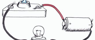
The fundamental law of electrical engineering is Ohm's law
The fundamental law of electrical engineering is undoubtedly Ohm's Law. Named, like most laws of physics, after its discoverer, the German physicist Ohm, it reads:
The current strength of a section of an electrical network is directly proportional to the voltage applied to this section and inversely proportional to its resistance.
In symbolic expression, Ohm's Law looks like this:
I=U÷R, where I is the current strength in the circuit (Ampere), U is the network voltage (Volts), R is the network resistance (Ohm).
In this form, Ohm's law has no practical application in the electrical engineering of residential and industrial buildings. Let me remind you that alternating voltage is used to power buildings and slightly different laws of electrical engineering apply here. But Ohm's law is one of the bases underlying all formulas and all electrical calculations.
The law of the relationship (correspondence) of voltage, current and power in an electrical circuit has practical application. It is derived mathematically from Ohm's law and is based on two algebraic formulas expressing physical laws:
P=U×I, where P is the power of the electrical network (Watt), U is the voltage, I is the current.
I=U÷R, where I is current, U is voltage, R is resistance.
If you sit a little, remember simple algebra and manipulate these two formulas, you can get a hint diagram in which all four quantities are: U; I; R; The P's are mathematically related to each other.
The practical application of these mathematical formulas of electrical laws can be applied in the calculation of a simple 220-volt electrical network without electric motors.
For example: Lighting one room with 20 incandescent light bulbs. The network voltage is constant and equal to 220 volts. The power of each light bulb is 25 watts.
By simple multiplication we get the following results:
Total network power consumption: 25 Watt × 20 light bulbs = 500 Watt.
Network current: 500 watts ÷ 220 volts = 2.3 amperes.
If there are three such rooms in an apartment, then the total operating current in the network will be 3 × 2.3 watts = 6.9 Amperes.
In accordance with this calculation, you can select the rating of the lighting circuit breaker for the entire apartment. We round up 6.9 amperes to the value of the ratings of commercially available machines. This is 10 amps.
Conclusion: A simple calculation according to the basic law of electrical wiring made it possible to calculate the rating of the required circuit breaker.
Chapter 1. ELECTRIC CIRCUIT AND ITS BASIC LAWS
Chapter 1. ELECTRIC CIRCUIT AND ITS BASIC LAWS
Basic information about the structure of matter and the physical nature of electricity
The electronic theory of the structure of the atom of a substance has established that all substances, both simple and complex, consist of molecules, and molecules of atoms.
The smallest particle of a substance that retains its properties is called a molecule. A molecule is a chemical combination of two or more atoms. An atom is the smallest particle of an element that retains the element's chemical characteristics. A chemical element is a component of a substance, built from identical atoms.
Simple substances - copper, aluminum, zinc, lead, etc. - consist of identical atoms of a given substance. Molecules of complex substances consist of several atoms of various chemical elements. For example, table salt (sodium chloride) consists of chlorine atoms and sodium atoms. Water molecules contain hydrogen atoms and oxygen atoms.
An atom consists of protons, neutrons and electrons. Protons and neutrons are grouped at the center of the atom and form the nucleus. Protons are positively charged, neutrons have no charge. Electrons are located and rotate on shells at various distances from the nucleus.
The atoms of different elements are different from each other. Since there are over 100 different elements, there are over 100 different atoms.
The simplest atom is the hydrogen atom: it has only one electron, located in the first electron shell. The helium atom (Fig. 2, a) has two electrons located on the first shell (K), the oxygen atom (Fig. 2, b) has two on the first and six on the second (a total of eight, located on the K and L shells).
The outer shell is called the valence shell and the number of electrons it contains is called the valency. The farther the valence shell is from the nucleus, the less attractive forces each person experiences from the nucleus.
valence electron.
Thus, the potential for an atom to lose increases. It is the valence electrons that determine the ability of the atoms of a given element to enter into chemical bonds with each other and with atoms of other elements, as well as the electrical conductivity of various materials.
Physical nature of electricity. Many electrical phenomena are explained on the basis of the electronic theory of atomic structure. According to this theory,
If the valence shell electrons receive enough energy from external forces, they can leave the atom and become free electrons, moving randomly from atom to atom.
In this case, they cease to be neutral. Atoms that have lost some of their electrons become positively charged ions. Atoms that gain excess electrons become negatively charged ions.
If electrons or ions accumulate in any body, then they say that electricity has accumulated in the body. Such a body becomes electrically charged and acquires electrical properties. These properties are essentially a manifestation of electrical forces acting between electrons and atomic nuclei.
Electric charges . The amount of electricity contained in a charged body is called electric charge. Charges have two signs: positive (indicated by the “+” sign) and negative (indicated by the “-”) sign.
In the International System of Units SI, electrical charges, i.e. the amount of electricity, are measured in Coulombs (C). If 6.29·1018 electrons passed through the wire, then they say that an amount of electricity equal to 1 C passed through the wire.
When electric charges (electrically charged bodies) interact (Fig. 2), electrical forces of attraction or repulsion arise between them.
Kirchhoff's laws
The values of currents and voltages for complex branched circuits can be found using Kirchhoff's laws.
Kirchhoff's first law establishes the relationship between currents for nodes in an electrical circuit to which several branches approach. According to this law, the algebraic sum of the currents of the branches converging at a node of an electrical circuit is equal to zero:
ΣI=0
In this case, currents directed to the node are taken with one sign (for example, positive), and currents directed from the node are taken with the opposite sign (negative). For example, for node A (Fig. 17, a)
I1 + I2+ I3- I4- I 5 = 0
Transforming this equation, we find that the sum of currents directed to a node in the electrical circuit is equal to the sum of currents directed from this node:
I1 + I2+ I3= I4+ I 5
Kirchhoff's second law establishes the relationship between e. d.s. and voltage in a closed electrical circuit. According to this law, in any closed contour the algebraic sum e. d.s. equal to the algebraic sum of the voltage drops across the resistances included in this circuit:
ΣE = ΣIR
When drawing up formulas characterizing Kirchhoff's second law, the values of e. d.s. E and voltage drops IR are considered positive if the directions of e. d.s. and currents in the corresponding sections of the circuit coincide with an arbitrarily chosen direction of traversal of the circuit. If the directions e. d.s. and currents in the corresponding sections of the circuit are opposite to the selected direction of bypass, then such e. d.s. and voltage drops are considered negative.
Let us consider, as an example, an electrical circuit in which there are two sources with electromotive forces E1 and E2 (Fig. 18a), internal
resistances and two receivers with resistances R1 and R2 . Applying Kirchhoff's second law for this circuit and choosing the direction of its traversal clockwise, we obtain:
E1 - E2 = IR01 + IR02 + IR1 + IR2
At the same time, e. d.s. E1 and current I coincide with the selected direction of bypassing the circuit and are considered positive, and e. d.s. E2 , opposite to this direction, is considered negative.
If in an electrical circuit e. d.s. sources of electrical energy when bypassing the corresponding circuit are directed towards each other (see Fig. 18, a), then such a connection is called counter. In this case, based on Kirchhoff’s second law, the current
I = (E1 - E2)/(R1 + R2 + R01+R02).
If e. d.s. sources of electrical energy have the same direction along the contour (Fig. 24, b), then such a connection is called consonant and the current
I = (E1 +E2)/(R1 + R2 + R01+R02)
In some cases, such inclusion is unacceptable, since the current in the circuit increases sharply.
If there are branches in the electrical circuit (Fig. 18, c), then various currents I1 and I2 . According to Kirchhoff's second law
(E1 - E2) = I1R01 + I1R1 - I2R2 -I2R02 - I2R3+ I1R4
When composing this equation, e. d.s. E1 and current I1 are considered positive, since they coincide with the accepted direction of bypassing the circuit, e. d.s. E2 and current I2 are negative.
11. Serial, parallel and mixed connections of resistors.
A significant number of receivers included in an electrical circuit (electric lamps, electric heating devices, etc.) can be considered as some elements having a certain resistance. This circumstance gives us the opportunity, when drawing up and studying electrical circuits, to replace specific receivers with resistors with certain resistances. There are the following methods of connecting resistors (receivers of electrical energy): serial, parallel and mixed.
Serial connection . When connecting several resistors in series, the end of the first resistor is connected to the beginning of the second, and the end of the second to
the beginning of the third, etc. With such a connection, the same current I
The serial connection of receivers is illustrated in Fig. 19, a. Replacing the lamps with resistors with resistances R1, R2 and R3 , we obtain the circuit shown in Fig. 19, b. If we assume that in the source R0 = 0, then for three series-connected resistors, according to Kirchhoff’s second, we can write:
E = IR1 +IR2 +IR3 = I( R1+ R2+ R3 ) = IRtotal ;
where: Rtot = R1+ R2+ R3
Therefore, the equivalent resistance of a series circuit is equal to the sum of the resistances of all series-connected resistors.
The voltage U at the source terminals is equal to the sum of the voltages at each of the series-connected resistors.
It is advisable to connect in series only receivers with the same resistance. Otherwise, the applied voltage of the electrical energy source is distributed unevenly between them and individual receivers may be under an unacceptably high voltage for them.
When receivers are connected in series, a change in the resistance of one of them entails a change in the voltage at the other receivers connected to it. If the electrical circuit breaks in one of the receivers, the current stops in the others.
With a parallel connection, the receivers are connected between two points of the electrical circuit, forming parallel branches (Fig. 20, a). Replacing the lamps with resistors with resistances R1, R2 and R3 , we get the circuit shown in Fig. 20, b.
U is applied to all resistors . Therefore, according to Ohm's law:
I1 = U/R1 , I2 =U/R2 , I3 = U/R3
Current in the unbranched part of the circuit according to Kirchhoff’s first law I=I1+I2 +I3 or
I= U/R1 + U/R2 + U/R3 = U (1/ R1 + 1/ R2+ 1/ R3) = U/Req
Therefore, the equivalent resistance of the circuit under consideration when three resistors are connected in parallel is determined by the formula
1/ Req = 1/ R1 + 1/ R2+ 1/ R3
As the number of resistors connected in parallel increases, the resulting resistance decreases.
When the receivers are connected in parallel, they are all under the same voltage and the operating mode of each of them does not depend on the others. This means that the current passing through any of the receivers will not have a significant effect on the other receivers. Whenever any receiver is turned off or fails, the remaining receivers remain on.
A mixed connection is a connection in which some of the resistors are connected in series, and some in parallel. The equivalent circuit resistance for a mixed connection is usually determined by the method
transformation, in which a complex chain is transformed in successive stages into a simple one.
Thermal effect of current
When an electric current passes through a conductor, as a result of collisions of free electrons with its atoms and ions, the conductor heats up. The amount of heat generated in a conductor during the passage of electric current is determined by the Joule-Lenz law. The amount of heat released Q is equal to the product of the square of the current I2, the resistance of the conductor R and the time t for the current to pass through the conductor:
Q =I2Rt.
Permissible strength and current density. The conversion of electrical energy into heat has found wide application in technology.
However, in electrical machines and devices, in wires, the conversion of electricity into heat is not only useless, but also impairs their performance, and in some cases can cause damage and accidents.
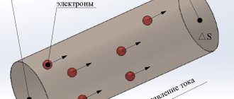
Each conductor, depending on the conditions in which it is located, can pass, without overheating, a current of strength not exceeding a certain permissible value. To determine the current load of wires, the concept of permissible current density J (current strength I per 1 mm2 conductor cross-sectional s
J=I/s
The permissible current density depends on the wire material (copper or aluminum), the type of insulation used, cooling conditions, cross-sectional area, etc.
Exceeding the permissible current in a conductor can cause an excessive temperature rise, as a result of which the insulation of the wires of electric motors, generators and electrical networks overheats, chars and even burns, which can lead to a short circuit and fire. In order to prevent unacceptable increases in current, provisions must be made in all electrical installations to automatically disconnect from sources of electrical energy those receivers or circuit sections in which an overload or short circuit occurs. For this purpose, fuses and circuit breakers are widely used in technology.
Heating in the transition resistance. Increased heating of the conductor, as follows from the Joule-Lenz law, can occur not only due to the passage of a high current through it, but also due to an increase in the resistance of the conductor. Therefore, for the reliable operation of electrical installations, the resistance at the junction of individual conductors is of great importance. If the electrical contact is loose and the conductors are poorly connected (Fig. 22), the electrical resistance in these places (the so-called transition resistance of the electrical contact) increases greatly, and increased heat generation occurs here. As a result, the area where the conductors are loosely connected will pose a fire hazard, and significant heating can lead to complete burnout of the poorly connected conductors. To avoid this when connecting wires to e. p.s. their ends are carefully cleaned, tinned and soldered into cable lugs, which are securely bolted to the terminals of electrical machines and devices. Special measures are also taken to reduce the transition resistance between the contacts of electrical devices that turn the current on and off.
Electromagnetic induction.
When a conductor crosses magnetic field lines, an emission appears in it, or, as they say, is induced. d.s. This phenomenon is called electromagnetic induction.
Emergence of e.m.f. is explained by the action of magnetic field forces on free electrons located in conductors. Free electrons, under the influence of these forces, will begin to move along the conductor (Fig. 37). As a result of this movement, free electrons will accumulate at one end of the conductor and a negative electric charge will arise, and at the other end, due to a lack of electrons, a positive charge will appear.
The potential difference at the ends of the conductor is numerically equal to the emf induced in the conductor. Induction of e.m.f. in a conductor occurs regardless of whether it is connected to any electrical circuit or not. If you connect the ends of this conductor to any receiver of electrical energy, then under the influence of the potential difference, electric current will flow through the closed circuit.
The value of induced e. d.s. determined by Faraday's law of electromagnetic induction. It is formulated as follows. Induced e. d.s. e
is directly proportional to the magnetic field induction
B
, the length of the conductor
l
and the speed of its movement
v
in the direction perpendicular to the field lines,
e = Blv.
If the conductor moves along the field lines, i.e., as if sliding along them, then the emf. does not arise in it.
Direction of induced e. d.s. determined by the right hand rule. The right hand should be positioned so that the magnetic lines of force enter the palm, and the thumb should be aligned with the direction of movement of the conductor (i.e., the direction of its speed v), then the extended four fingers will indicate the direction of the induced emf. e (Fig. 38). Using this rule, it is easy to verify that when the direction of movement of the conductor changes, the direction of the induced emf will also change.
Induce e.m.f. in a stationary conductor, you can move the magnetic field itself or change the magnetic flux. Moreover, the faster the magnetic flux changes, the greater the induced emf.
Methods of inducing e. d.s. in electric cars. The phenomenon of electromagnetic induction is widely used in various electrical machines and devices. The design of electric generators is based on this principle.
motors and transformers. To induce e. d.s. They usually use three methods:
- change in current in coil 1 (Fig. 39, a), in the magnetic field of which the second coil 2 is located. In this case, the magnetic flux covered by the second coil continuously changes, and in it, as well as in the first coil, electromotive forces e1 and e2 . This method is used in transformers;
- rotation of the magnetic field created by permanent magnets or electromagnets 3 relative to the fixed coils 4 (Fig. 39, b). In this case, the magnetic flux penetrating each coil continuously changes, and em are induced in them. d.s. e. This method is used in AC machines;
- rotation of turns 6 or coils in a constant magnetic field created by fixed permanent magnets 5 or electromagnets (Fig. 39, c). In this case, the magnetic flux covered by each turn or coil continuously changes, as a result of which e is induced in them. d.s. This method is used in DC electric machines.
Eddy currents.
A changing magnetic flux can induce e. d.s. not only in wires or coil turns, but also in massive steel cores, casings and other metal parts of electrical installations. These e. d.s. are the cause of the appearance of induced currents that act in massive metal parts, short-circuiting in their thickness. Such currents are called eddy currents.
For example, when the magnetic flux created by coil 1 (Fig. 40, a) changes, eddy currents are induced in its steel core 2, closing in a plane perpendicular to the magnetic field lines. Eddy currents also arise in the cores of 3 armatures and rotors of electric machines when they rotate in a magnetic field (Fig. 40, b). The nature of eddy currents is the same as the currents induced in ordinary wires or coils. Due to the very low resistance of massive conductors, eddy currents even with a small induced e.g. d.s. reach very high values, causing excessive heating of these conductors.
Ways to reduce the harmful effects of eddy currents . In electrical machines and devices, eddy currents are usually undesirable, since they cause heating of the metal cores, create energy losses (so-called losses from eddy currents), reduce the efficiency of electrical machines and devices, and have a demagnetizing effect according to Lenz's rule. To reduce the harmful effects of eddy currents, two main methods are used.
The cores of electrical machines and devices are made of separate steel sheets 1 (Fig. 41) with a thickness of 0.35-1.0 mm, isolated from one another by a layer of insulation 2 (varnish film, scale formed during annealing of sheets, etc.). Due to this, the path for the propagation of internal currents is blocked and the cross-section of each individual conductor through which these currents flow is reduced, which leads to a decrease in current strength.
Self-induction.
E.m.f., induced in a conductor or coil as a result of a change in magnetic flux created by a current passing through the same conductor or coil, is called e.m.f. d.s. self-induction. This e. d.s. occurs with any change in current: when closing and opening electrical circuits, as well as when changing the current in the circuit. The faster the current changes in a conductor or coil, the greater the rate of change of the magnetic flux penetrating them and the greater the e. d.s. self-induction is induced in them. Direction e. d.s. self-induction is determined by Lenz's rule. E.m.f. self-induction always has a direction in which it prevents the change in the current that caused it. Consequently, as the current in the conductor (coil) increases, the e.g. induced in them. d.s. self-induction will be directed against the current, i.e., it will prevent its increase, and vice versa, when the current decreases in the conductor (coil), e.m. appears. d.s. self-induction, coinciding in direction with the current, i.e., preventing its decrease. If the current in the coil does not change, then the emf. no self-induction occurs.
In an electrical circuit (Fig. 42, a), consisting of a resistor with resistance
R and
coil K , current i is created by the combined action of source voltage U and emf. With. self-induction eL induced in the coil.
When connecting the circuit in question to a source of e. d.s. self-induction eL (see solid arrow) restrains the increase in current strength. Therefore, the current i reaches the steady-state value I=U/R (according to Ohm’s law) not instantly, but over a certain period of time (Fig. 42, b). During this time, a transient process occurs in the electrical circuit, during which eL and i . In the same way, when the electrical circuit is turned off, the current i does not decrease instantly to zero, but due to the action of e. d.s. eL (see dashed arrow) gradually decreases.
Inductance. The ability of various conductors (coils) to induce emf. is estimated by inductance L. It shows what e. d.s. self-induction occurs in a given conductor (coil) when the current changes by 1 A for 1 s. Inductance is measured in henry (H).
Switching overvoltages. E is especially strong. d.s. self-induction when opening circuits containing coils with a large number of turns and with steel cores (windings of generators, electric motors, transformers, etc.), i.e. circuits with high inductance. In this case, the resulting e. d.s. self-induction eL can be many times higher than the voltage U of the source and, summed with it, cause overvoltages in electrical circuits (Fig. 43, a), called switching (arising during switching - switching of electrical circuits). They are dangerous for the windings of electric motors, generators and transformers, as they can cause breakdown of their insulation.
Big E.
d.s. Self-induction also contributes to the occurrence of an electric arc in electrical devices that switch electrical circuits. For example, at the moment the switch contacts open (Fig. 43, b), the resulting emf. self-induction greatly increases the potential difference between the open contacts of the switch and breaks through the air gap. The resulting electric arc is maintained for some time by the emf. self-induction, which thus delays the process of turning off the current in the circuit. Mutual induction.
Mutual induction is the phenomenon of inducing e. d.s. in a conductor or coil when the magnetic flux created by another conductor (coil) changes. E. induced in this way. d.s. it is called e. d.s. mutual induction.
Control questions:
1. What are the ways to enhance magnetic fields?
2. What is magnetic induction, magnetic flux, magnetic field strength?
3. What are the main characteristics of ferromagnetic materials?
4. In what cases does a magnetic field create mechanical forces and how are they determined?
5. What is induced emf. and how is its meaning and direction determined?
6. What are eddy currents and what ways are there to reduce their harmful effects?
7. What is e. d.s. self-induction and mutual induction?
Chapter 1. ELECTRIC CIRCUIT AND ITS BASIC LAWS
Kirchhoff's laws
The electrical work of any room is carried out in the form of closed, working electrical circuits. The two main laws that determine processes in electrical networks are Kirchhoff's laws. There are two of them. Both of them apply to both direct and alternating currents.
Kirchhoff's first law states:
The total value of currents directed to an electrical network node is equal to the total value of currents directed from the node.
In practice, the operation of Residual Current Devices (RCDs) is based on Kirchhoff's first law. The operation of the RCD is to turn off the power supply to the network when leakage currents occur. During normal operation, the total value of the current flowing into the electrical network is equal to the value of the current flowing out of it. If the equality of currents is violated, then there is a leak in the network. The RCD is designed and connected in such a way that if there is a current leak, the RCD detects it and disconnects the power supply.
Kirchhoff's second law states:
Any closed loop of an alternating electrical network has equal values of complex voltages and EMF (electromotive forces) on all passive elements of the network.
Note: Complex voltage is the value of AC mains voltage.
Practical application can be explained on any apartment power supply group. For clarification, let's look at an apartment.
No matter how many power supply groups there are in the apartment, at any outlet or lamp the voltage in the network (in operating mode) will be 220 volts.
One more basic law of electrical engineering needs to be remembered.
Joule-Lenz law
The Joule-Lenz law establishes a connection between the current “running” through a conductor, its resistance and the heat that is released.
In mathematical symbolism, the Joule-Lenz law looks like this:
Q=I2×R×t, where Q is the amount of heat generated in the conductor, in Joules; I is the current strength; R is the resistance of the conductor; t is the time it takes for the current to pass in seconds.
As information: Lenz is a Russian physicist Emilius Christianovich Lenz. Russian physicist, electrical engineer, physical geographer. 1804-1865 years of life.
Speaking about the practical application of the Joule-Lenz law, it is difficult to name in which part of electrics it does not manifest itself. Electric heaters, electric water heaters, thermal curtains, selection of circuit breakers, thermal relays in automation and much more.
Of course, these are not all the basic laws of electricity. In their meaning, these laws are of fundamental importance.
Other articles on the site
- Automatic circuit breakers
- Types of power transmission line supports by material
- Types of supports by purpose
- Overhead power lines with SIP wires
- Wooden supports for overhead power lines
- Reinforced concrete power transmission line supports
- Reinforced concrete power transmission line supports
- Protection of humans from electric shock, direct and indirect contact
- How does a 380 Volt low voltage consumer receive electricity?
- Cable network wells installation stages
Electromotive force
Electromotive force E (EMF) characterizes the ability of an induced field to cause an electric current. The unit of measurement is volt (V). Energy sources can be sources of emf and current. This manual only discusses emf sources. The EMF source is characterized by two parameters: the values of the EMF (E) and internal resistance (r0). An EMF source whose internal resistance can be neglected is called an ideal source. A real EMF source has a certain value of internal resistance. At the EMF source, the internal resistance is significantly less than the load resistance (RH) and the electric current in the circuit depends mainly on the magnitude of the EMF and the load resistance. The EMF source has the following graphic symbols.
The current-voltage characteristic of the EMF source has the form:
Rice. 1
The relationship between the voltage at the source terminals and its EMF has the form:
U = E – r0× I (for a real EMF source)
U = E (for an ideal source).
Electrical resistance R is a value characterizing the resistance of a conducting medium to the movement of free electrical charges (current). The unit of measurement is Ohm. The reciprocal of resistance is called electrical conductivity G. The unit of measurement is siemens (Cm).