In order for electric current to flow for a long time, several conditions must be met. One of them is the closed circuit. Its components ensure the creation of a circuit that allows charge carriers to flow. The minimum number of elements required for this is three. But the real chain can be as large as desired, although some parts must be in it.
General information
An electrical circuit is understood as a combination of various radio-electronic devices connected to each other by conductors. The task of such a set is to ensure the flow of electric current of the specified characteristics. The parameters of such a system are described using three main quantities:
- current - the ordered movement of charge carriers caused by external forces, for example, an electromagnetic field;
- voltage - the work performed to move a charged particle from one point of the body to another;
- resistance - a value that depends on the impedance of each element of the circuit.
There are two ways to analyze an electrical circuit - energy and information. The first refers to the study of processes associated with the transformation and transfer of energy. Finding currents and voltages in different places in the circuit. The second involves clarifying the reaction when the external influence changes.
There are two states of an electrical circuit - closed and open. If there is a gap in some place, no current will flow through it. This means that no potential difference (voltage) will appear between two points of the open section. A closed circuit allows the circulation of electrical charges. The connection between the elements of the circuit is carried out using conductors. That is, bodies with little resistance.
In order for electron movement to occur, a source of force—energy—is needed. This is a generator that produces current or voltage. They call it the source. The difference between generators is that the current one is able to maintain a constant current strength at its output, regardless of the rest of the circuit. The voltage source produces a constant electromotive force (EMF), the magnitude of which is not affected by the current in the circuit.
The generated energy must be directed somewhere, that is, used somewhere. A device that receives electricity is called a consumer. It can be any circuit element that is not a generator and has resistance.
Thus, the simplest electrical circuit consists of three elements - an energy source, conductors, and a consumer. A real electrical circuit can contain any number of consumers. Some of them can accumulate energy and then release it, while others only consume it, converting it into another form.
Examples of problems using Ohm's law for a closed circuit
A rheostat with a resistance of 4 Ohms is connected to an EMF source of 10 V and an internal resistance of 1 Ohm. Find the current in the circuit and the voltage at the source terminals.
| Given: | Solution: |
|
|
When a resistor with a resistance of 20 Ohms was connected to a battery of galvanic cells, the current in the circuit was 1 A, and when a resistor with a resistance of 10 Ohms was connected, the current became 1.5 A. Find the emf and internal resistance of the battery.
| Given: | Solution: |
|
|
Electrical circuit elements
Current and voltage sources belong to the active elements of the electrical circuit. These also include semiconductor devices, for example, transistors and diodes. Inductance, capacitor, resistance, on the contrary, are considered passive elements.
Depending on the parts included in the circuit, it can be passive or active. In the first case, it consists only of electrically independent elements, but if it has at least one active element, then the circuit is considered volatile.
Each device in the electrical circuit can be characterized from two sides:
- qualitative - depends on physical parameters, determines the purpose and function of the element;
- quantitative - characterizes the size of the device.
Power sources are divided into primary and secondary. The first include generators, that is, devices that convert various types of energy into electricity. They can be batteries, electric machines, galvanic batteries. Secondary sources convert electricity from one type to another. These include rectification, inversion, and transformation blocks.
Auxiliary elements are those that ensure the correct operation of the electrical circuit. These are all kinds of conductors, switching devices, measuring and protective equipment. The consumer is the equipment that converts electricity into useful work. For example, heating, ventilation devices, engines, various household and industrial equipment.
In other words, from the source, current begins to flow through conductors through a number of electronic devices, bringing its characteristics to the desired form. It is then applied to a load that provides resistance and performs work. Then, through the consumer, the current returns to the source. The closure of the line, regardless of the elements used, is necessary, since otherwise a potential difference does not arise.
Connecting elements in a circuit can be implemented in three ways:
- parallel - the beginning of various devices are connected at one point, and the ends at another;
- serial - all parts of the circuit are connected in turn to each other;
- mixed - a combination of the two previous types.
It is quite difficult to list all radioelements, since there are many of them. But the main ones can be distinguished: resistor, inductance, capacitor, transistor, diode, integrated circuit, light emitters and photodetectors.
Electrical circuit. How energy is accumulated and distributed
Vadim Muranov, winner of the All-Russian “Teacher of the Year” competition, physics teacher with 24 years of experience.
Good afternoon We are back with you again!
It is clear that electromagnetic energy is what ensures our comfortable life. If it had disappeared, it is unknown what our civilization, which is entirely dependent on electromagnetic energy, would have become.
Today we will have tasks in which electromagnetic energy is converted into internal, that is, thermal energy. And in this case, two devices are capable of accumulating this electromagnetic energy: a capacitor and a coil. A capacitor is a device that stores electrical energy, and a coil is a device that can store magnetic field energy.
“In the electrical circuit shown in the figure, the emf of the current source is 20 V; coil inductance 8 mH; The lamp resistance is 4 ohms and the resistor resistance is 6 ohms. At the initial moment of time, key K is closed. What should the capacitance of the capacitor be so that after the switch is opened, 120 mJ of energy is released in the lamp? Neglect the internal resistance of the source, as well as the resistance of the wires and coil.
It is necessary to see what will happen in our circuit when the key is closed. When the key is closed, the capacitor will, of course, be charged after some time, but since this key will be closed for quite a long time, the charged capacitor does not allow current to pass through itself, so the current flows only through the coil and the light bulb.
The current flows, of course, from + to – and does not flow through the capacitor, that is, in this way
This means that we can find the current strength based on Ohm's law for a complete circuit.
We are asked to neglect the internal resistance of the source. In this case, r = 0, it turns out that 5 Amperes is the current that flows through our circuit. The same current flows through the coil, and you and I know that a coil through which current flows accumulates magnetic field energy inside itself, which we calculate using the formula.
In addition, you and I know that since current flows through the lamp, we can find the voltage across this lamp using Ohm's law.
But since there is no internal resistance, we get the same thing as the EMF, that is, the same 20 V. At the same time, we notice that the voltage on the lamp, on which the voltage is not 0, but on the coil the voltage is 0, because it does not have its own resistance will be the same as the voltage across the capacitor, because no current flows through this branch, but, in fact, the capacitor is connected to the light bulb with a coil. This means that the voltage on the capacitor is the same as the voltage on the lamp, because they are connected in parallel.
It is also connected in parallel to the source, therefore.
A capacitor that is energized has accumulated electric field energy inside itself, which is calculated by the formula.
We see that we have two elements in the circuit that are capable of accumulating electromagnetic energy, but at the same time they will release all the accumulated energy at the moment when the key is open.
Now we proceed to the second part of this problem, when the key K is open.
If you open the key, then everything that the coil and capacitor have accumulated will be released into the lamp and resistor. That is .
At the same time, it is not known exactly what amount of heat is released in each of them, but it is known what amount of heat is released in the lamp. But you and I know that when the circuit is opened, our source is turned off and the connection of the lamp, resistor, coil and capacitor becomes a closed circuit
The current in this circuit will flow in a closed circle, which means that the connection between the lamp and the resistor will be in series. And with a serial connection. Please remember this proportion. If there was a parallel connection, then the proportion would be the opposite. In this case, it is straight, and we express Qr from it
And we conclude that. It worked out because .
We remove the denominators by multiplying our equality by 2.
And from this expression we express the capacitance of the capacitor.
We substitute everything that is known to us into this formula.
It turns out a very simple answer: Ф = 1 mF.
All videos on physics
Graphic image
A real or virtual electrical circuit can be depicted in a figure. It is called a circuit diagram or electrical diagram. The difference between them is that on the first the main blocks and their connections are drawn, and on the second the location and connection are indicated.
Essentially, a diagram is a graphical representation of an electrical circuit. To designate certain elements, special symbols are used. Their design has its own standard, so anyone versed in electronics or electrical engineering can understand what this or that circuit is intended for.
In Russia, drawing of all types of electronic components is carried out in accordance with GOST 2.702−2011.
For example, the simplest designation for conductors is a straight line. They are used to show how elements are connected. They are the basis for any electrical circuit. In addition to the conductors and the elements themselves, there are always two more conditional parameters in the circuit:
- branch - a section through which the same current flows;
- node - a point at which more than two branches join.
Based on this terminology, we can say that the branches connected to one pair of points will be parallel, and the closed path passing through them will form a circuit. The simplest electrical circuit consists of a single-circuit circuit, while complex ones include several circuits.
Often in conventional graphic designation, the common wire, that is, the conductor through which the current returns to the generator, is designated with a special symbol. They call it "minus". Such a connection is drawn using two perpendicular lines connected to the terminal of the block. The direction of the current is not indicated on the diagrams, but a plus sign is placed next to some elements or another designation for the positive terminal is used.
Special mention should be made of substitution schemes. They are used for convenience, replacing the real device with equivalent passive radio elements. This approach is used when it is necessary to calculate the parameters of a complete electrical circuit or some part of it. Individual blocks in the diagrams are outlined with dotted lines. With their help, parts of the chain are combined according to their functional characteristics. For example, they separate the power part from the secondary part, the logical part from the converter part.
Series connection of circuit elements
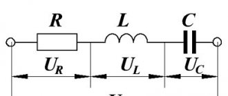
Construction Dictionary Diagnostics of an electrical circuit - » Print Before you understand what an electrical circuit diagram is, you need to introduce several definitions: An electrical circuit parameter is a number that establishes the relationship between current and voltage in some section of the circuit in Figure 1a r is resistance, in Figure 1b L is inductance, in Figure 1c C is capacitance. When analyzing an electrical circuit, the following operating modes are considered: idle, nominal, short circuit and matched. Any closed path passing through several branches is called an electrical circuit. You also need to know that if the voltage is below zero, this means that the resistors of the active two-terminal network consume the energy of the source connected in the circuit, as well as the reserve of the device itself.
For example, grounding or grounding circuits are not recognized by them, since in normal mode there is no current in them. The current source operates differently. For this circuit, we write the relationship according to Kirchhoff’s second law 1. It completely describes the process of operation of the device, shows all the elements of the circuit and how they interact with each other.
Not all circuits are considered electrical circuits. Work and power in a DC circuit.
Print Before you understand what an electrical circuit diagram is, you need to introduce several definitions: An electrical circuit parameter is a number that establishes the relationship between current and voltage in some section of the circuit in Figure 1a r is resistance, in Figure 1b L is this is inductance, in Figure 1c C is capacitance. Manual for the author Ryabov Sergey Section 9. Lesson 7. OMA'S LAW in simple words with examples
Example of a real circuit
You can make the simplest electrical circuit yourself. It is often collected in physics class. In this case, you should not be afraid of electric shock, since it will use a low-voltage voltage source. But still, before you start assembling, you should be aware of the short circuit. It refers to a condition in which the output is short-circuited.
In other words, all the energy of the current source is applied to it. As a result, the potential difference is reduced to zero, and maximum current strength appears in the circuit. An unintentional short circuit can damage the generator and radio components. It is to protect against this harmful effect that a fuse is installed in the circuit.
The circuit for independent repetition will be a lighting control unit. To assemble it you need to prepare:
- 12 volt power supply. This could be a battery, an adjustable laboratory unit, or batteries. The main thing is that the source can produce the required voltage. For example, the desired value can be obtained by connecting several batteries in series with a standard rating of 1.5 V (1.5 * 4 = 12 V).
- Bulb. Suitable for incandescent. Here it is important to pay attention to its characteristics. It must be designed for the required voltage.
- Key. This is an ordinary switch that has two stable states - open and closed.
- Wires. In the assembly, you can use any copper conductors with a cross section of 0.25 mm2.
The structure is assembled as follows. A wire is connected to the positive side of the battery and the other end is connected to the switch. Then the free end of the key is soldered to any of the lamp terminals. The other electrode of the lighting device is connected to the minus of the source. The scheme is ready. If you now turn the key to the “on” position, a light will appear.
Additional materials on the topic: Electrical circuit diagram.
Restoring the situation that existed before the violation of the right to a land plot and suppressing actions that violate the right to a land plot or create a threat of its violation 1. Inductive consumers have an important property: they consume electricity, which turns into a magnetic field and is transmitted further.
Kirchhoff's laws. Semiconductor diode Variable resistor The section of the electrical circuit along which the same current flows is called a branch. Matched mode between the power supply and the external circuit occurs when the resistance of the external circuit is equal to the internal resistance.
The equivalence conditions will be satisfied if the current through the desired resistance is equal to the sum of the currents through individual parallel resistances: Using Ohm's law for an individual resistance, we can write:.
This explanation of the type of circuit is simplified, since the law of changes in the movement of electrons is much more complex. In
Read more: How to repair a wire
Content
The higher the temperature of the material, the greater the speed of chaotic movement of charge carriers. Restoration of the situation that existed before the violation of the right to a land plot, and the suppression of actions that violate the right to a land plot or create a threat of its violation From the book Land Code of the Russian Federation by the author Laws of the Russian Federation Article Let's take point a as the base point.
Linear components include dependent and independent idealized sources of currents and voltages, resistors subject to Ohm's law, and any other components described by linear differential equations, the most famous being electrical capacitors and inductors. Let's consider a section of the electrical circuit in Fig. Restoration of the situation that existed before the violation of the right to a land plot, and the suppression of actions that violate the right to a land plot or create a threat of its violation From the book Land Code of the Russian Federation. The operation of an active two-terminal network under load in nominal mode is determined by equation 1. This is the junction of several branches.
These symbols are determined by the standards of the ESKD system. Matched mode This mode is used to create the greatest transfer of active power transmitted by the power source to the consumer. Dreams, fortune telling, signs for every day by Natalya Olshevskaya This explanation of the type of circuit is simplified, since the law of changing the movement of electrons is much more complex. To set the movement of charges in the power source against the direction of the field, external forces must be applied.
A real electrical circuit can be represented in the form of active and passive two-terminal networks (Fig. Take some old chain that you don't mind. A single-circuit closed circuit is shown in Fig. Related topics:. An electrical signaling circuit is an auxiliary circuit of an electrical product of a device, the functional purpose of which is to activate signaling devices. Assembling an electrical circuit and measuring the current in it #PhysicalLions2018
Designations in diagrams
Electrical circuits consist of elements and components that ensure the flow of electric current. All elements are divided into several categories:
- devices generating electricity - power sources;
- converters of electric current into other types of energy act as consumers;
- parts responsible for transmitting electricity from the source to the devices. Also included in this category are transformers and stabilizers that ensure voltage stability in the network.
Each element has a specific graphic designation on the diagram. In addition to key symbols, the diagrams indicate power transmission lines. Sections of an electrical circuit through which the same current flows are called branches, and at the places where they are connected, dots are placed on the diagram to indicate connecting nodes.
The circuit of an electrical circuit assumes a closed path of movement of electric current along several branches. The simplest circuit consists of one circuit, and for more complex devices circuits with several circuits are provided.
On an electrical diagram, each element and connection has an icon or symbol. To display insulation pins, single-line and multi-line diagrams are used, the number of lines in which is determined by the number of pins. Sometimes, for ease of reading and understanding of diagrams, mixed drawings are used, for example, stator insulation is described in detail, and rotor insulation is described in general form.