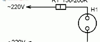
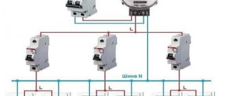
Wiring diagram for the telpher for power supply 380
Work on connecting an electric hoist (380V) in accordance with technical requirements can only be carried out by specially trained specialists.
Before starting work, the equipment is de-energized and only after that the network and control cables are connected in accordance with the connection diagram located on the side of the electrical panel cover. A copy of the diagram is attached by the manufacturer to the electric hoist passport. The device is connected to the power supply using a circuit breaker and fuses. The circuit breaker is designed to interrupt an unloaded electrical circuit when carrying out technical work on electrical wiring or mechanical components. It is recommended to place the circuit breaker and fuse block in hard-to-reach places, and work with it should be free and easy. Power cables must have increased resistance to mechanical damage. When connecting, it is necessary to check the compliance of the mains voltage specified in the standard table. After connection, the buttons are checked for proper operation. To do this, press the “lift” button, and if the load moves down, you need to swap the connection points.
After installing the lifting equipment, it is necessary to check the integrity of the cables, the absence of damage to the mechanical components of the equipment and the possibility of de-energizing the hoist using the mains switch.
Let's consider the connection option using the example of a hoist produced by Balkansko Echo R. Bulgaria. Series T10, T39 Hoists of the T45, T78 series are connected in the same way
Telphers are supplied in two versions:
Hoist crane beams
Electrical circuit diagram
List of electrical equipment elements
Electric overhead overhead crane with a lifting capacity of 3.2 tons.
The crane is designed for lifting and transport operations in indoor production and warehouse premises, with a normal environment at an ambient temperature of -40 to +40 degrees Celsius with low intensity of handling work.
Faucet composition:
- load-bearing beam
- movable beam
- rigid beam
— electric hoist
The cranes are equipped with a hoist with an appropriate lifting height.
Cranes can be made both without docking locks and with locks.
Docking locks are installed on cranes with consoles of at least 600 mm.
Rigid end beam for a crane with a lifting capacity of 1 ton. consists of an idle trolley and a driven trolley with a geared motor, connected to each other by beams, at the ends of which guide rollers are installed.
Technical data:
Scheme
Table:
www.xn—-7sbbta0aknzgs0a0gsa.xn--p1ai
Firstly
For reasons of safe operation of the device, when connecting a frequency generator (or any other device) to the power supply, it is imperative to install a circuit breaker. The machine is installed in front of the frequency switch.
Moreover, if the frequency converter is connected to a network with three-phase voltage, then it is necessary to install a machine that is also three-phase, but with a common shutdown lever. This will allow you to turn off power from all phases simultaneously if there is a short circuit or severe overload on at least one phase.
If the frequency converter is connected to a network with single-phase voltage, then a single-phase machine is used. But at the same time, the current of one phase is taken into account, multiplied by three.
When connecting a three-phase machine, its operating current is determined by the current of one phase.
It is definitely forbidden to install a circuit breaker into the neutral cable gap, both with a single-phase connection and with a three-phase one. Such a connection only looks identical in appearance (it is a mistake to understand that there is only one circuit and it does not matter where it is broken). In fact, if the phase cables break, when the machine is triggered, the power is completely turned off and there will be no phases on the device circuits at all. It is safe. And when the machine with a broken zero is triggered, the operation of the device will stop. But at the same time, the motor windings and frequency circuits will remain energized, which is a violation of safety regulations and is dangerous for humans.
Also, under no circumstances does the grounding cable break. Like the zero, they must be connected to the corresponding buses directly.
How to install the telpher
As a rule, electric hoists are supplied already assembled, so you should carefully inspect the mechanism. It should be free of moisture, dirt and dust. Locking mechanisms, bolted and contact connections - everything must be in good order. A whole set of equipment is used to install the hoist:
After installation, the following distance parameters must be correctly observed:
- between the rail and the wheel of the trolley - 4 mm;
- at least 100 mm from the hoist to the ceiling;
- from the electric hoist to the walls or railings of the building - at least 60 mm;
- at least 400 mm from other installations.
When connecting the hoist, first of all you need to:
- prepare a connection diagram for the mechanism,
- clear the area for installing the crane,
- provide unhindered access to installers,
- attach the travel limiter of the mobile unit to the rail.
The telpher is a complex mechanism; do not install it yourself. It's better to contact specialists. Thus, poor placement and failure to comply with safety standards can become serious causes of breakdowns and injury to personnel.
Source: lebedka.ua
What advantages does the device itself have?
It has the following advantages:
- Unlike a crane, it has compact dimensions. You can always roll up all the loading equipment into a small truck.
- You can use it anywhere that has a strong enough beam or hook to grab onto.
- A rail guide under the ceiling is enough to place the hoist on rollers and give it a greater degree of mobility.
- Several units can work in tandem synchronously, which makes it possible to transport long loads, such as bundles of pipes.
- There is a huge amount of specialized equipment supplied optionally. These could be barrel grips, dynamometers, daily load capacity recording systems, etc.
- Very high ascent speed. Some models can deliver up to 10-12 meters in one minute. Sometimes they can be equipped with setting this parameter from the remote control. This is very useful when loading racks.
- The strength of the operator does not matter.
How much does this product cost?
Our price for an electric hoist (telpher) is low, because we work without intermediaries. You can always purchase these devices of various load capacities, as well as a large number of parts and additional equipment. Each product has a safety margin of 4 to 1, which is specially made in case one of the chains breaks or twists in the wind. Abuse of this resource is strictly prohibited.
Classification
The lifting mechanism of a manual worm hoist with a plate load chain forming a double chain hoist is presented in detail in the work. With the help of these devices, the following are switched off: the lifting mechanism when the hook suspension reaches the uppermost position, the movement mechanism when the hoist stops approach the stops.
The number of the supervision service and its structure must be determined by the owner of the cranes, taking into account their number, operating conditions, and agreed in writing with the Rostechnadzor authorities.
The switches S7, S8 are influenced by the rope handler through a mechanical kinematic chain. Once again I would like to emphasize the importance of correctly connecting the hoist and the control panel to it. The current price level for electric hoists is as follows: For domestic standard sizes - from 80 thousand.
Along with the rope, the rope layer also moves on the drum - a device necessary not so much for laying the rope in streams, but for turning on and off the limit switches for over-lifting and over-lowering. Why is it so important to connect the hoist correctly? Hoists are universal devices designed for moving heavy objects along vertical and horizontal planes.
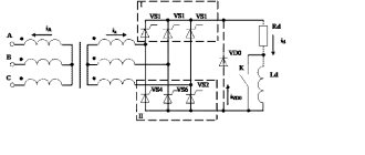
Electrical equipment of electric hoists Electrical circuit diagrams of hoists with different designs have much in common and noticeable differences. The gearbox housing has a drain plug 16 and a vent plug 7 7. Another delivery option is with frequency converters for the smoothest starting and braking of drives.
Hoists designed for installation on single girder cranes are supplied with a six-button control panel. Along with the rope, the rope layer also moves on the drum - a device necessary not so much for laying the rope in streams, but for turning on and off the limit switches for over-lifting and over-lowering. It is powered by direct current from the rectifier in the starting cabinet. Power in mechanics is usually denoted by the letter N, in electrical engineering by the letter P. The lifting mechanisms shown in Fig.
TE-050 electric hoist for 500 kg
Excluding manual hoists and car jacks, electric hoists are the most common lifting machines in the world. Lifting motor Asynchronous two-speed electric motor with cone rotor and stator and built-in asbestos-free cone brake.
The designs of electric hoists also vary somewhat depending on their load capacity. Satellites in Fig. Screw channels for the rope are made along the surface of the drum. It is powered by direct current from the rectifier in the starting cabinet. Electric hoist PRORAB LT 800 P
Electric hoist TE 025 31100-23U2
#1 as1x
- Our users
- Messages: 245
- Gender: Man
- Car: Opel Rekord Caravan 2.0S
- Real name: Vladislav
- Place of residence: Kharkov
Hello! I decided to hang a hoist to remove the engine. It looks like it's new, but it's been there for a long time. There is no network connection cable. It is designed for both 220V and 380V. The diagram has barely survived, but part of it has been destroyed by time. Searches on the Internet only yielded a schematic diagram, from which it is not clear what to connect where.
I ask for help in connecting to a 220V network. Maybe someone has the same thing or has dealt with similar devices. I will be very grateful!))
see also
Comments 27
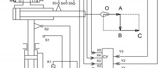
the diagram should look something like this, this is only a control circuit (if you need a power circuit, I’ll finish it, but everything is simple there) provides “protection against back-switching” and restriction of movement by limit switches (if provided for by the design)
ps please excuse the sloppy handwriting
what comes with the waist?
what comes with the waist?
Hoist Carriage (horizontal movement)
Then everything is much simpler. Remove the remote control and replace it with this block with the circuit. The right side of the diagram I drew (or its analogue) is already assembled on the hoist. if you show me a diagram of the hoist or at least the connection of the wires on the remote control itself, then I will be able to more accurately and in detail describe to you what to connect where
Then everything is much simpler. Remove the remote control and replace it with this block with the circuit. The right side of the diagram I drew (or its analogue) is already assembled on the hoist. if you show me a diagram of the hoist or at least the connection of the wires on the remote control itself, then I will be able to more accurately and in detail describe to you what to connect where
Then everything is much simpler. Remove the remote control and replace it with this block with the circuit. The right side of the diagram I drew (or its analogue) is already assembled on the hoist. if you show me a diagram of the hoist or at least the connection of the wires on the remote control itself, then I will be able to more accurately and in detail describe to you what to connect where
Then everything is much simpler. Remove the remote control and replace it with this block with the circuit. The right side of the diagram I drew (or its analogue) is already assembled on the hoist. if you show me a diagram of the hoist or at least the connection of the wires on the remote control itself, then I will be able to more accurately and in detail describe to you what to connect where
Then everything is much simpler. Remove the remote control and replace it with this block with the circuit. The right side of the diagram I drew (or its analogue) is already assembled on the hoist. if you show me a diagram of the hoist or at least the connection of the wires on the remote control itself, then I will be able to more accurately and in detail describe to you what to connect where
not exactly what I wanted to see)) but it doesn’t matter, the main thing is to see what kind of remote control you have in order: - 220 V needs to be supplied to terminals 1 and 2 (this is the power supply for your control unit) where to get it - it doesn’t matter, from the power supply of the hoist or separately carry it out - you open the cover of the remote control from your hoist, turn it over, look (5 wires should go there) - if you look at the opened remote control from behind, on the right side, there is a metal plate along all the buttons, to which a common wire is connected. we take this wire and connect it to terminal 3 of your radio remote control - on the left side of the opened remote control opposite each button there is also a wire connected, we take these wires and reconnect them one by one (from the “up” button - to terminal 5; from the “down” button - to terminal 6; from the “left” “right” buttons - to terminals 7 and 8, respectively) - try (if everything works, shorten the wire, mount the module on the hoist, use it)))
IMPORTANT NOTE: this circuit is applicable only if the rated current of the hoist does not exceed 5A (you need to look in the hoist’s passport); if the rated current of the hoist is higher than 5A, it is necessary to assemble a circuit with intermediate relays or starters.
Thank you very much I will look for the instructions for the hoist
Reversible connection diagram for a magnetic starter
Greetings, dear readers of the site elektrik-sam.info!
In order to start the electric motor in forward and reverse directions, a reversible control circuit is used on a magnetic starter.
This article discusses in detail the step-by-step operation of the circuit. For a diagram in which the motor operates only in one direction, without reverse, see the article non-reversible magnetic starter connection diagram .
At the conclusion of this article, watch a video demonstrating the detailed operation of the engine reverse starting circuit.
First, let's consider a reversible connection circuit with a 220V magnetic starter coil, and then the operation of the circuit.
Phases A, B and C of the supply voltage are supplied to the terminals of the asynchronous motor through:
Electrical circuits and electrical equipment of cranes
Construction machines and equipment, reference book
Category:
Electrical diagrams of tower cranes
Electrical circuits and electrical equipment of cranes
There are basic and installation electrical diagrams of cranes.
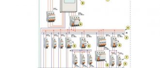
The circuit diagram includes the general electrical connection diagram of the protective panel, controllers and motors. It is used when setting up and repairing equipment.
The wiring diagram includes an accurate diagram of all electrical connections of the main, auxiliary and lighting circuits, including connections of the protective panel, motors, controllers, lamps, and starting resistors. The installation diagram allows for the installation of all electrical equipment (laying cables and connecting equipment).
Electrical equipment of the SBK-1 crane
To drive the crane mechanisms, MT three-phase crane asynchronous electric motors with a closed phase rotor are used. The main characteristics of the crane electric motors are given in table. 3.
Table 3
The motors of the crane movement and boom rotation mechanisms are controlled using drum controllers, and the cargo winch motor is controlled by a command controller and a magnetic controller. The characteristics of the controllers are shown in table. 4.
Table 4
Protection of electric motors from short circuit currents is carried out using maximum relays connected to two phases of each motor. The relay regulation limits are set at two to three times the switching current value of the rated current. The technical parameters of the relay are given in table. 5.
Table 5
All crane mechanisms are equipped with shoe brakes with long-stroke KMT magnets. The KMT-103 magnet is used on the cargo winch, and the KMT-100 is used on the boom rotation and crane movement mechanisms, having a traction force of 35 and 8 kg, respectively, and a maximum armature stroke of 50 and 20 mm.
To limit the working movements and load capacity of the crane, standard limit switches KU-131 and KU-132 are provided. Switch KU-131 is installed on the boom and is designed to limit the lifting height of the hook and the load capacity of the crane; switches KU-132 (2 pcs.) are mounted on the longitudinal beam of the portal between the running wheels and serve to limit the movement of the crane along the rail tracks.
The current is supplied to the spotlight and limit switch mounted on the boom, and to the lighting lamp on the counterweight console through a four-ring pantograph mounted on the crane head.
Electrical diagram of the SBK-1 crane
The load lifting electric motor is controlled by means of an auxiliary circuit for controlling the acceleration contactors, reversing contactors and the linear contactor of the magnetic controller (Fig. 99, 100). The electric motors of the boom rotation and crane movement mechanisms are controlled directly by drum controllers.
The auxiliary control circuit connects in series the coils of the linear contactor, the maximum relays, the emergency switch, the zero contacts of all controllers and, through the control (return) button of the linear contactor, the linear switch. After the line contactor has been switched off due to tripping of the limit switches due to abnormal motor operation, it can be switched on again using the reset button.
The specified control circuit wiring provides zero interlocking and the line contactor cannot be turned on by pressing the control button until the controllers are set to zero positions. The line contactor, in turn, provides zero protection for the electrical equipment of the crane, since when it is de-energized, the contactor automatically breaks the power supply circuit to the crane. When voltage is applied, the contactor cannot turn on arbitrarily and, therefore, to continue operation of the crane mechanisms, it is necessary to set the controllers to zero positions and turn on the contactor reset button.
When the controller is turned on “for lifting”, current flows through the coil of the lifting contactor, the contacts of the acceleration and descent contactor, the limit switch of the limiter of the hook lifting height and load capacity, and also simultaneously enters the brake magnet of the lifting mechanism, which causes the brake pads to release.
Rice. 99. Schematic diagram of the SBK-1 crane:
Rice. 100. Electrical installation diagram of the SBK-1 crane:
This circuit has interlocks that prevent the activation of the lift contactor when the descent contactor is not turned off in the event of a rapid transfer of the controller handle from the “descent” to the “raise” position; turning on the electric motor without starting resistance.
Switching the handle of the command controller is accompanied by sequential activation of the acceleration contactors and short-circuiting of the starting resistance stages, as a result of which smooth acceleration of the engine is ensured.
The electrical circuit of the crane provides the so-called power lowering of loads and countercurrent braking (counter-switching), for which the command controller provides five and three handle positions, respectively.
To lower the nominal (largest at a given boom radius) load in the “power descent” mode, the controller handle is set to the third position. Lowering a light load corresponds to the fifth position; in the case of lowering the rated load in this position of the handle, the engine operates in generator mode at a speed within 1.1 of the rated speed.
To lower the load in braking mode, the controller handles are set to the “descent-brake” position, in which the electric motor rotates in the upward direction. In the first and second positions, the load is lowered at a speed of about 0.8 of the nominal speed; in the third position, the engine is fully engaged in “lifting” and the load can be stopped after some downward movement. This engine switching circuit must be used in case of sudden failure of the load lifting mechanism when the load is suspended on the hook.
Electrical equipment of the BK-2 crane
To drive the crane mechanisms, crane asynchronous electric motors of three-phase current MT with a phase rotor and AO squirrel-cage closed design are used. Basic data of electric motors are given in table. 6.
Table 6
The motors of the load lifting and crane movement mechanisms are controlled by the KT-2005 drum controllers (in the latest models, NT-51 cam controllers), the boom rotation mechanism by the KT-2006 controller, and the boom lifting mechanism by the P-224 magnetic reversing starter using buttons. The magnetic starter is designed for a rated current of 20 A.
Protection of electric motors from short circuit currents is carried out using maximum relays connected to two phases of each motor and mounted on the protective panel.
All crane mechanisms are equipped with shoe brakes with MO short-stroke magnets.
To limit working movements, load capacity and blocking, standard limit switches KU-131 and KU-132 are used. The KU-131 switch is installed on the boom head and is designed to limit the lifting height of the hook and the lifting capacity of the crane; switches KU-132 (2 pcs.) are mounted on the running trolley and serve to limit the movement of the crane; switch VU-250, which limits the boom reach, is installed on the boom winch. To block the opening of the hatch, a simple B-10 switch is used.
The current supply to all motors, apparatus and lighting fixtures located on the rotating part of the crane - counterweight, cabin, boom - is made through a nine-ring current collector mounted on the crane head.
Electrical diagram of the BK-2 crane
The electric motors of the mechanisms for lifting loads, turning the boom and moving the crane are controlled directly by drum controllers, and the mechanism for changing the boom reach is controlled by a magnetic starter (Fig. 101).
Protective panel B, installed in the control cabin, provides maximum and zero protection for crane motors.
When the controllers are turned on, current flows through the protective panel devices, limit switches, motors and brake magnet coils, which causes the brake pads to release.
When starting the engines, the controllers are used to alternately turn off the starting resistance sections until the engine fully accelerates, when the rotor is short-circuited.
The magnetic starter has two contactors for raising and lowering the boom; its control circuit includes two start buttons - “up” and “down”, a “stop” button and limit switches.
Electrical equipment of crane T-72
To drive the friction reversible winch of the crane, a crane squirrel-cage electric motor AO is used, which is turned on and off using a conventional three-pole switch.
Rice. 101. Schematic electrical diagram of the BK-2 crane: 1 - scan of the KT-2005 controller drum; 2 — scan of the drum of the KT-2006 controller; 3 — scan of the drum of the KT-2005 controller; 4 — brake magnets; 5 — cargo winch motor; 6 — jib winch motor; 7 — motor of the turning mechanism; 8—motor of the crane movement mechanism; 9 — grounding on the rotating part of the crane; 10—grounding on the tap; 11 — development of the protective panel; 12—zero contacts of controllers
The engine is protected by tubular fuses. Electricity is supplied to the motor and lighting fixtures through a flexible cable and current collector.
Read more: Cranes for the construction of residential and civil low-rise buildings
Category: – Electrical diagrams of tower cranes
Home → Directory → Articles → Forum
stroy-technics.ru