Reading diagrams is impossible without knowledge of the conventional graphic and letter designations of the elements. Most of them are standardized and described in regulatory documents. Most of them were published in the last century, and only one new standard was adopted, in 2011 (GOST 2-702-2011 ESKD. Rules for the execution of electrical circuits), so sometimes a new element base is designated according to the principle “as who came up with it.” And this is the difficulty of reading circuit diagrams of new devices. But, basically, the symbols in electrical circuits are described and are well known to many.
Incorrect, but visual symbols and symbols in electrical diagrams are not needed
Two types of symbols are often used on diagrams: graphic and alphabetic, and denominations are also often indicated. From this data, many can immediately tell how the scheme works. This skill is developed over years of practice, and first you need to understand and remember the symbols in electrical circuits. Then, knowing the operation of each element, you can imagine the final result of the device.
Types of circuits in electrical
Drawing and reading different diagrams usually require different elements. There are many types of circuits, but in electrical engineering the following are usually used:
- Functional ones, which display the main components of the device, without detail. Outwardly it looks like a set of rectangles with connections between them. Gives a general idea of the functioning of the object.
The functional diagram shows the blocks and connections between them
Schematic diagram details the device
The installation room displays the location and route of cables/communication lines
There are many other types of electrical circuits, but they are not used in home practice. The exception is the route of cables passing through the site and the supply of electricity to the house. This type of document will definitely be needed and useful, but it is more of a plan than an outline.
Basic images and functional features
Switching devices (switches, contactors, etc.) are built on contacts of various mechanics. There are make, break and switch contacts. The normally open contact is open; when it is switched to operating state, the circuit is closed. The break contact is normally closed, but under certain conditions it operates, breaking the circuit.
The switching contact can be two or three position. In the first case, first one circuit works, then another. The second one has a neutral position.
In addition, contacts can perform different functions: contactor, disconnector, switch, etc. All of them also have a symbol and are applied to the corresponding contacts. There are functions that are performed only by moving contacts. They are shown in the photo below.
Functions of moving contacts
Basic functions can only be performed by fixed contacts.
Functions of fixed contacts
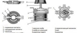
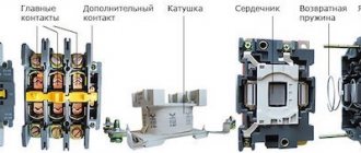
Design and principle of operation
The basis of the starter is an inductance coil and a magnetic circuit, consisting of moving and stationary parts. The fixed part is the lower one and is fixed to the body, the upper one is spring-loaded and can move freely.
A coil is mounted at the bottom of the magnetic circuit, and the rating of the contactor changes in direct proportion to its winding. Coils are available from 12 to 380 volts.
As for the upper part of the magnetic circuit, there are movable and fixed groups of contactors.
When there is no power, the springs press out the part of the magnetic circuit located at the top. In this case, the contacts are in the idle or initial state. When voltage is applied, an electromagnetic field is generated in the coil, under the influence of which the upper part of the core is attracted. As a result, the contacts change their position.
Symbols for single line diagrams
As has already been said, single-line diagrams indicate only the power part: RCDs, automatic devices, automatic circuit breakers, sockets, circuit breakers, switches, etc. and connections between them. The designations of these conventional elements can be used in electrical panel diagrams.
The main feature of graphic symbols in electrical circuits is that devices similar in principle of operation differ in some small detail. For example, a machine (circuit breaker) and a switch differ only in two small details - the presence/absence of a rectangle on the contact and the shape of the icon on the fixed contact, which display the functions of these contacts. The only difference between a contactor and a switch designation is the shape of the icon on the fixed contact. It's a very small difference, but the device and its functions are different. You need to look closely at all these little things and remember them.
Designations of elements on a single line diagram
There is also a small difference between the symbols of the RCD and the differential circuit breaker. It also only functions as moving and fixed contacts.
The situation is approximately the same with relay and contactor coils. They look like a rectangle with small graphic additions.
Symbols of contactor coils and relays of different types (pulse, photo relay, time relay)
In this case, it’s easier to remember, since there are quite serious differences in the appearance of the additional icons. With a photo relay it’s so simple - the rays of the sun are associated with the arrows. A pulse relay is also quite easy to distinguish by the characteristic shape of the sign.
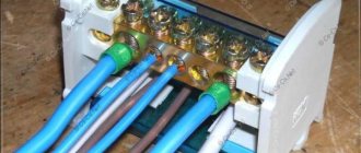
Symbols for detachable (plug-plug) and dismountable (terminal block) connections), measuring instruments
A little easier with lamps and connections. They have different “pictures”. A detachable connection (such as a socket/plug or socket/plug) looks like two brackets, and a detachable connection (such as a terminal block) looks like circles. Moreover, the number of pairs of checkmarks or circles indicates the number of wires.
Contactor connection
Before connecting, it is sometimes useful to make sure the product is working. To make it clear how to check the contactor, it is necessary to find out what algorithm is used to carry out this procedure:
- assessment of condition by visual inspection;
- setting up the magnetic system;
- checking the integrity and insulation resistance of current-carrying elements;
- adjustment of the contact system.
Ease of movement can be checked using a short circuit. If a strong hum is noted, the screws that hold the core and armature are tightened. If frozen metal particles or deposits are found on the contacts, it is necessary to remove them with a file, without using any lubricant.
Before starting the process, it is strongly recommended that you familiarize yourself with the detailed connection diagram.
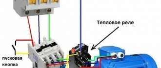
As a rule, you should first route the incoming cables and secure them with special fasteners. Then the output wires are connected and secured. A thermal relay or a start button may be located in front of the contactor (a rectifier will be required if the button station will use alternating current).
The contact and connection diagram does not depend on the manufacturer and standard sizes of the product. Special marking of contacts allows you to understand the purpose of each of them. You can get a lot of information from the network on how to connect a contactor, but it is not recommended to do such work yourself without having the necessary skills and knowledge.
A large assortment of modular devices designed to work with electrical wiring, as well as other analogues for working with various motor starters, is available on the official website. Photographic materials will help you get an idea of what the contactor looks like, and the characteristics and descriptions will allow you to quickly select the appropriate model.
Picture of buses and wires
In any circuit there are connections and for the most part they are made by wires. Some connections are buses - more powerful conductor elements from which taps can extend. Wires are indicated by a thin line, and branches/connections are indicated by dots. If there are no points, it is not a connection, but an intersection (without an electrical connection).
Designation of communication lines, buses and their connections/branches/intersections
There are separate images for buses, but they are used if they need to be graphically separated from communication lines, wires and cables.
How wires, cables are designated, the number of cores and methods of laying them
On wiring diagrams it is often necessary to indicate not only how the cable or wire runs, but also its characteristics or installation method. All this is also displayed graphically. This is also necessary information for reading drawings.
How switches, switches, sockets are depicted
There are no standards-approved images for some types of this equipment. So, dimmers (light regulators) and push-button switches remained without designation.
But all other types of switches have their own symbols in electrical diagrams. They come in open and hidden installations, respectively, there are also two groups of icons. The difference is the position of the line on the key image. In order to understand in the diagram what type of switch we are talking about, this must be remembered.
There are separate designations for two-key and three-key switches. In the documentation they are called “twin” and “twin”, respectively. There are differences for cases with different degrees of protection. In rooms with normal operating conditions, switches with IP20, maybe up to IP23, are installed. In wet rooms (bathroom, swimming pool) or outdoors, the degree of protection should be at least IP44. Their images differ in that the circles are filled in. So it's easy to distinguish them.
Read also: Compressor for cleaning your computer
Symbols of switches in drawings and diagrams
There are separate images for the switches. These are switches that allow you to control turning the light on/off from two points (there are also three, but without standard images).
The same trend is observed in the designations of sockets and socket groups: there are single, double sockets, and there are groups of several pieces. Products for rooms with normal operating conditions (IP from 20 to 23) have an unpainted middle; for wet rooms with a housing of increased protection (IP44 and higher), the middle is tinted dark.
Symbols in electrical diagrams: sockets of different types of installation (open, hidden)
Having understood the logic of the designation and remembering some initial data (what is the difference between the symbolic image of an open and hidden installation socket, for example), after a while you will be able to confidently navigate the drawings and diagrams.
Lamps on diagrams
This section describes the symbols in the electrical circuits of various lamps and fixtures. Here the situation with the designations of the new element base is better: there are even signs for LED lamps and fixtures, compact fluorescent lamps (housekeepers). It’s also good that the images of lamps of different types differ significantly - it’s difficult to confuse them. For example, lamps with incandescent lamps are depicted in the form of a circle, with long linear fluorescent lamps - a long narrow rectangle. The difference in the image of a linear fluorescent lamp and an LED lamp is not very big - only dashes at the ends - but even here you can remember.
Image of lamps (incandescent, LED, halogen) and lamps (ceiling, built-in, wall-mounted) on diagrams
The standard even includes symbols in electrical diagrams for ceiling and pendant lamps (socket). They also have a rather unusual shape - circles of small diameter with dashes. In general, this section is easier to navigate than others.
Elements of electrical circuit diagrams
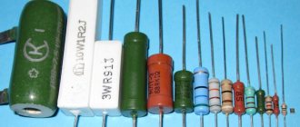
Schematic diagrams of devices contain a different element base. Communication lines, terminals, connectors, light bulbs are also depicted, but in addition, there is a large number of radio elements: resistors, capacitors, fuses, diodes, thyristors, LEDs. Most of the symbols in the electrical circuits of this element base are shown in the figures below.
Designation of electrical elements on device diagrams
Image of radioelements on diagrams
Rarer ones will have to be looked for separately. But most circuits contain these elements.
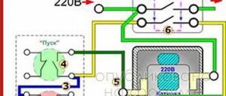
Connection diagrams for a magnetic starter with a 220 V coil
Before we move on to the diagrams, let’s figure out what and how these devices can be connected. Most often, two buttons are required - “start” and “stop”. They can be made in separate housings, or they can be a single housing. This is the so-called push-button post.
Buttons can be in the same housing or in different ones
Everything is clear with individual buttons - they have two contacts. One receives power, the other leaves it. There are two groups of contacts in the post - two for each button: two for start, two for stop, each group on its own side. There is also usually a ground terminal. Nothing complicated either.
Connecting a starter with a 220 V coil to the network
Actually, there are many options for connecting contactors; we will describe a few. The diagram for connecting a magnetic starter to a single-phase network is simpler, so let's start with it - it will be easier to understand further.
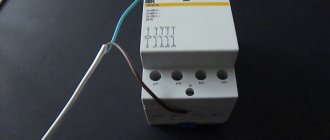
Power, in this case 220 V, is supplied to the coil terminals, which are designated A1 and A2. Both of these contacts are located at the top of the case (see photo).
This is where you can supply power to the coil.
If you connect a cord with a plug to these contacts (as in the photo), the device will be in operation after the plug is inserted into the socket. In this case, any voltage can be applied to the power contacts L1, L2, L3, and it can be removed when the starter is triggered from contacts T1, T2 and T3, respectively. For example, a constant voltage from a battery can be supplied to the inputs L1 and L2, which will power some device that will need to be connected to the outputs T1 and T2.
Connecting a contactor with a 220 V coil
When connecting single-phase power to the coil, it does not matter which output is supplied with zero and which with phase. You can switch the wires. Even most often, the phase is supplied to A2, since for convenience this contact is located on the bottom side of the housing. And in some cases it is more convenient to use it and connect the “zero” to A1.
But, as you understand, this scheme for connecting a magnetic starter is not particularly convenient - you can also supply conductors directly from the power source by building in a regular switch. But there are much more interesting options. For example, you can supply power to the coil through a time relay or a light sensor, and connect the street lighting power line to the contacts. In this case, the phase is connected to contact L1, and zero can be taken by connecting to the corresponding coil output connector (in the photo above it is A2).
Diagram with start and stop buttons
Magnetic starters are most often installed to turn on an electric motor. It is more convenient to work in this mode if there are “start” and “stop” buttons. They are connected in series to the phase supply circuit to the output of the magnetic coil. In this case, the diagram looks like the figure below. note that
Letter symbols in electrical diagrams
In addition to graphic images, elements on the diagrams are labeled. It also helps to read the diagrams. Next to the letter designation of an element there is often its serial number. This is done so that later it is easy to find the type and parameters in the specification.
Letter designations of elements on diagrams: basic and additional
The table above shows international designations. There is also a domestic standard - GOST 7624-55. Excerpts from there with the table below.
A contactor is one of the types of electromagnetic relays.
It has a coil in its design, when voltage is applied to it, the core is retracted, after which the contacts actually close.
Many people confuse contactors with starters. How do they differ from each other?
A contactor is essentially a single device designed to close and open electrical circuits. And the starter is a kind of complex device that performs the same function, but with additional elements in its circuit.
For example, various types of protection or trigger buttons.
The big problem is that many people use these terms differently.
The main thing is to understand the functionality of each equipment.
Below are explanations of the symbols and names of popular brands of starters and contactors PML, KME, PAE, PMA.
From them you can find out what certain alphanumeric symbols mean and how they are deciphered.
It turns out that just from the name alone you can understand:
- what product is this
- what functionality does it have?
- what additional capabilities does it contain?
To view each starter type, click on the appropriate tab.
However, in addition to the name, a lot of information is contained on the contactor body itself.
Let's look at the example of two products from IEK KMI and Schneider Electric LC1D25, what inscriptions and designations manufacturers put on the housings, how they are deciphered and what they mean.
Let's start with the contactor from Schneider Electric. The maximum possible power connected to the contactor in horsepower (HP - horsepower) is indicated on the side edge. This power depends on the supply voltage.
In a number of countries, horsepower is still used, although there are recommendations from the international metrology organization that horsepower should be eliminated from use.
The following are general recommendations for selecting circuit breakers or fuses.
- the inscription CB - Circuit Breaker refers to automatic machines
- Fuse – to fuses
The maximum operating voltage (a.c. max) must be specified.
Cont. current is the continuous rated current at load category AC1.
To put it simply, category AC1 is a load such as an iron or an ordinary heater.
AWG 6-14 Cu - shows the cross-section of wires that can be connected to the contacts.
Measurements are in Western units. In order to find out the analogue of our section in mm2, you will need to use the AWG to mm2 conversion table.
Torque 20lb.in – the torque with which the terminals can be tightened.
More accurate numbers in conventional units of measurement can also be found in the technical data on the manufacturer’s website, or use a special program here that converts lb-in to Nm (newton meters).
Lb-in stands for pounds per square inch.
High-quality contactors always have inscriptions indicating the presence of certificates to which this mechanism corresponds.
Ith-40A – conditional thermal current in open design. Simply put, this is the current that the contactor can pass through itself under normal environmental conditions.
Ui=690V – rated insulation voltage of the product.
IEC/EN 60947-4-1 – starter compliance with this standard. GOST R50030.4.1-2012 is our modified analogue of this standard.
Uimp=6kV – permissible pulse overvoltage.
A separate plate indicates the possible powers connected to the contactor, depending on the supply voltage.
Powers are already registered in kilowatts. Some may wonder why there is such a difference depending on the voltage.
Read also: Compressor check valve gasket
This is explained simply. By and large, the contactor does not care what voltage the load is designed for. The most important thing is the amount of current flowing through its contacts.
And if the voltage is 2 times greater, i.e. 200V, then when connecting the same load of 1 kW, a current will flow through the product 2 times less than I = 5A.
Therefore, the lower the voltage, the less power the load can be connected to the contactor. At the same time, always pay attention to what type of load the data is indicated for.
For example, in this case, the powers are indicated for the AC3 load. An example of such a load is an asynchronous motor.
JIS C8201-4-1 is a Japanese industrial standard. Accordingly, the possible powers connected to the contactor are also specified here, depending on the supply voltage according to this standard.
Why is such a large and strange set of voltages prescribed? Because different countries have different standards that determine power voltage levels.
For example, in Japan, a regular outlet has 100 volts. And for powerful loads, 200V is already used.
Let's move on to the inscriptions on the front panel of the starter = contactor.
A1 and A2 are the control coil connection points.
The terminals themselves are marked in two alternative ways:
- number sequence 1-2-3-4-5-6
- alphanumeric. Top L1-L2-L3. Bottom T1-T2-T3.
Auxiliary contacts are marked in accordance with standards. There is one nuance that not everyone knows about.
The first digit of the designation is the serial number of the contact. And the second digit is the contact function.
For example, at the top you can see the inscriptions 13-21. Bottom 14-22.
That is, the first numbers 1-2 are the serial number of the contact. There is one auxiliary contact on the left, and a second on the right.
And the second number is the function. The number 1-2 is the common wire or part of the normally closed contact of the circuit.
The number 3-4 is part of the normally open contact. That is, by looking at the numbers, without unwinding or ringing the mechanism, without studying its diagram in the passport, you can immediately understand that 13-14 is normally open contact No. 1 (NO - normal open).
A 21-22 – normally closed contact No. 2 (NC – normal closed).
All other electromagnetic relays familiar to us have the same markings, making it easier to visually understand the functionality of the device. Here is an example of another relay and the designation of its contacts.
You don’t need to look for documentation for it to understand how to connect here or what function this or that screw terminal has.
The voltage of the coil that controls the starter is also required to be written on the housing.
The letter M7 (or another) is a definition of the coil type in the order number.
For example, if a coil burns out in your LC1D25 contactor, you will only need to indicate the voltage and its number M7 when ordering. You will know for sure that exactly the product will arrive, and the size you need.
Another important point that is worth paying attention to is the possibility of using different types of wires in the terminals. If the pads are copper, this means that it is unacceptable to use aluminum wires.
The cross-section and types of connected wires are indicated in the technical documentation.
With the IEK contactor everything is much simpler. Its marking is based on almost the same principle.
Alphanumeric designation of working terminals:
Reading electrical drawings requires certain knowledge, which can be gleaned from regulatory documents. A kind of “language” of reading is the symbols in electrical circuits - a system of signs and symbols, mainly graphic and alphabetic. In addition to them, denominations are sometimes indicated in numbers.
Agree, understanding standard designations is simply necessary for any home master. This knowledge will help you read an electrical diagram and independently draw up a wiring plan in an apartment or private house. We offer you to understand all the intricacies of writing project documentation.
The article describes the main types of electrical circuits, and also provides a detailed explanation of the basic images, symbols, icons and alphanumeric markers used in drawing up drawings for the electrical network.
Contactors and starters (page 7)
| Frequency band, MHz | Standard, dB (µV), for environment | |||
| 2 | 1 | |||
| Quasi-peak value | Average value | Quasi-peak value | Average value | |
| 0,15-0,50 | 79 | 66 | 66-56 | 56-46 |
| (decreases linearly with the logarithm of frequency) | ||||
| 0,50-5,00 | 73 | 60 | 56 | 46 |
| 5,00-30,00 | 60 | 50 |
Table 15 — Limit levels for radiated interference tests
| Frequency band, MHz | Standard, dB (µV/m), for environment | |
| 21), measuring distance 30 m | 1, measuring distance 10 m | |
| 30-230 | 30 | 30 |
| 37 | 37 | |
| 1) These tests can be carried out at a distance of 10 m at limit levels increased by 10 dB. |
APPENDIX A
(recommended)
Marking and identification of contactor terminals
and associated overload relays
A.1 General provisions
The contactor terminals and associated overload relays are identified to provide information about the function of each terminal, its location relative to other terminals, etc.
A.2 Marking and identification of contactor terminals
A.2.1 Marking and identification of coil terminals
In case of identification using alphanumeric markings, the terminals of the electromagnetic contactor coil should be designated A1 and A2.
The terminals of the tap coils should be marked with serial numbers A3, A4, etc.
Examples
Note - As a result, input and output pins can have either even or odd numbers.
The winding terminals of a coil with two windings should be marked A1, A2 (first winding) - B1, B2 (second winding).
A.2.2 Marking and identification of main circuit terminals
The terminals of the main circuits should be marked with single digits and alphanumeric designations.
NOTE The current alternative marking methods, i.e. 1-2 and L1-T2, will be gradually replaced by this method.
Alternatively, the pins can be identified on the circuit diagram supplied with the
apparatus.
A.2.3 Marking and identification of auxiliary circuit terminals Auxiliary circuit terminals should be marked or identified on the diagrams with two-digit numbers:
— the number in place of units is the functional number;
- the digit in the tens place is the serial number,
For example
A. 2.3.1 Functional number
Numbers 1, 2 and 3, 4 are assigned to circuits with normally open and closed contacts, respectively.
Note - Definitions of normally open and closed contacts are given in paragraphs. 2.3.12 and 2.3.13 GOST R 50030.1.
Examples
Note - The dots in these examples replace serial numbers added as appropriate.
The terminals of circuits with switching contact elements should be marked with numbers 1, 2 and 4.
Numbers 5, 6 (for normally closed contacts) and 7, 8 (for normally closed contacts) are assigned to the terminals of the auxiliary circuits, which include auxiliary contacts with special functions.
Examples
| Normally closed contact with delay when closing | Normally closed contact with delay when closing |
Terminals of circuits with switching contact elements with special functions should be marked with numbers 5, 6 and 8.
Example
Changeover contact
with deceleration in both directions
A.2.3.2 Sequence number
Terminals belonging to the same contact element should be marked with the same number. All contact elements with the same function must be distinguished by serial numbers.
Examples
| Four contact elements | Three contact elements |
The serial number on the terminals may not be indicated only if this is clearly indicated in the additional information supplied by the manufacturer or consumer.
or
| Device | Device | Scheme |
Note - The dots are used only to illustrate the relationship and are not used in practice.
A.3 Marking and identification of overload relay terminals
The terminals of the main circuits of the overload relay should be marked similarly to the terminals of the main circuits of the contactors (see A.2.2).
The terminals of the auxiliary circuits of the overload relay should be marked similarly to the terminals of the auxiliary circuits of contactors with special functions (see A.2.3). The first serial number is always 9; if the second output is required, then 0 is used instead of 9.
Examples
Alternatively, the pins can be identified on the circuit diagram supplied with the apparatus.
APPENDIX B
(required)
Special tests
B.1 General provisions
Tests to verify mechanical and electrical wear resistance are mandatory; checking the coordination of the crossing current between the starter and the associated circuit breaker is performed at the discretion of the manufacturer.
B.2 Mechanical wear resistance
B.2.1 General provisions
By convention, the mechanical durability of a contactor or starter design is defined as the number of no-load operating cycles achieved or exceeded by 90% of all devices of this type before maintenance or replacement of mechanical parts becomes necessary; however, normal maintenance is permitted, including replacement of contacts according to B.2.2.1 and B.2.2.3.
The preferred numbers of no-load operating cycles are (in millions):
0.001—0.003—0.01—0.03—0.1—0.3—1—3 and 10.
B.2.2 Checking mechanical wear resistance
B.2.2.1 Condition of the contactor of the starter to be tested
The contactor or starter should be installed as under normal operating conditions; in particular, the conductors should be connected as for normal use.
The test is carried out in the absence of voltage or current in the main circuit. The contactor or starter may be lubricated before testing if lubrication is specified for normal operating conditions.
B.2.2.2 Operating conditions
The control solenoid coils shall be applied to their rated voltage and, if appropriate, their rated frequency.
If a resistive or impedance resistance is connected in series to the coils, which is short-circuited or not during operation, the test should be carried out with these resistances connected as in normal operation.
Compressed air should be supplied to pneumatic or electro-pneumatic contactors or starters at rated pressure.
Manual starters should be operated as under normal operating conditions.
B.2.2.3 Test procedure
a) The test is carried out with an operating frequency corresponding to the intermittent duty class. However, the manufacturer has the right to increase the operating frequency if he considers that the contactor or starter is capable of meeting the requirements at the increased operating frequency.
b) For electromagnetic and electro-pneumatic contactors or starters, the excitation time of the control coil must be greater than the operating time of the contactor or starter, and the coil must be de-energized for such a time that the contactor or starter has time to come to rest in both extreme positions.
The number of operating cycles performed must be no less than the number of operating cycles at no load specified by the manufacturer.
Testing for mechanical wear resistance can be carried out separately on different parts of the starter that are not mechanically connected to each other, unless we are talking about mechanical blocking that has not previously been tested together with the contactor.
c) When testing contactors and starters equipped with shunt or undervoltage releases, at least 10% of the total number of openings must be made by these releases.
d) After every tenth of the total number of operating cycles according to B.2.1 is completed, before continuing the test:
— clean the entire contactor or starter without disassembling it;
— lubricate parts that, according to the manufacturer’s instructions, should be lubricated for normal operating conditions;
— adjust the stroke and pressure of the contacts, if the design of the contactor or starter allows.
e) During servicing there should be no replacement of any parts.
f) Star-delta starters have a built-in device that provides a time delay between a star fault and a delta fault, which if adjustable can be adjusted to its minimum setting.
g) Rheostatic rotary starters have a built-in device that provides a time delay between the closure in the starting and closed positions, if it is adjustable, it can be adjusted to its minimum setting.
h) Autotransformer starters have a built-in device that provides a time delay between closures in the starting and on positions; if it is adjustable, it can be adjusted to its minimum setting.
B.2.2.4 Required results
After the mechanical endurance test, the contactor or starter shall still be capable of operating under the conditions described in 7.2.1.2 and 8.3.3.2 at room temperature. There should be no loosening of the parts used to connect the conductors.
Any time relays or other automatic control devices must remain operational.
B.2.2.5 Statistical analysis of test results for contactors or starters
The mechanical durability of the contactor or starter design is established by the manufacturer and verified by statistical analysis of the results of this test.
For contactors or starters manufactured in small quantities, the tests described in B.2.2.6 and B.2.2.7 are not applicable.
However, for contactors or starters manufactured in small quantities and differing from the basic design only by changes in parts (i.e., without significant modifications) that do not have a noticeable effect on the characteristics, the manufacturer may assign mechanical wear resistance based on experience in operating similar designs, analysis of material properties and etc. and based on the analysis of test results for large-scale production devices of the same basic design.
After such assignment, one of two tests should be carried out, which the manufacturer must select as the most suitable in each particular case, for example, depending on the planned production volume or according to the conventional thermal current.
NOTE The test is not intended to be a lot-by-batch or consumer acceptance test.
8.2.2.6 Single stage test of eight contactors/starters
Eight contactors or starters are tested for mechanical durability.
If the number of failures does not exceed two, the test is considered passed.
8.2.2.7 Two-stage test of three contactors/starters
Three contactors or starters are tested for mechanical durability.
The test is considered positive if there are no failures, and failed if there is more than one failure. In the event of one failure, three additional contactors or starters are tested for the specified mechanical durability, and the test is considered passed in the absence of additional failures. The test is considered unsatisfactory if there are two or more failures.
Note - Both tests - one-stage (eight contactors/starters) and two-stage (three contactors/starters) - are given in tables II-A and III-A of GOST R 50779.71. The tests were selected as being based on tests on a limited number of contactors or starters with essentially the same statistical characteristics (10% acceptable quality level).
B.3
Electrical wear resistance
B.3.1 General provisions
With regard to resistance to switching wear, a contactor or starter is conventionally characterized by the number of operating cycles under load, according to the various categories of use in Table B.1, which it is capable of performing without repair or replacement of parts.
Since star-delta starters, two-stage autotransformer starters and rheostat rotor starters are operated under highly variable operating conditions, it is convenient not to establish standard test parameter values. However, the manufacturer is recommended to indicate the switching endurance of the starter under certain operating conditions; wear resistance can be assessed based on the test results of the starter components.
For categories AC-3 and AC-4, the test circuit must include inductors and resistors arranged to provide the required current, voltage and power factor in accordance with Table B.1; In addition, in category AC-4, a test circuit should be used to verify the making and breaking capabilities (see 8.3.3.5.2).
In all cases, the operating speed must be selected by the manufacturer.
Tests should be considered satisfactory if the values recorded in the test report differ from those specified only within the following tolerances:
- by current... ±5%
- voltage... ±5%
Tests shall be carried out on the contactor or starter under conditions in accordance with B.2.2.1 and B.2.2.2, using the methods, if appropriate, in B.2.2.3, except that replacement of contacts is prohibited.
After the test, the contactor or starter shall meet the operating requirements of 8.3.3.2 and withstand an insulation test voltage equal to twice the rated operating voltage Ue
, but not lower than 900 V, applied only according to 8.3.3.4.2 a) 1).
If the contactor included in the starter has already passed an equivalent test, the starter need not be retested.
1 - Checking the number of operating cycles under load. Switch-on and switch-off conditions for several application categories
| Application category | Rated operating current Ie ,A | Inclusion | Shutdown | ||||
| I / | U/U e | Cos j1) | Ic / | Ur/U e | Cos j1) | ||
| AS-1 | Any value | 1,0 | 1,0 | 0,95 | 1,0 | 1,0 | 0,95 |
| AS-2 | 2,5 | 0,65 | 2,5 | 0,65 | |||
| AS-3 | £ 17 | 6,0 | 1,0 | 0,17 | |||
| >17 | 0,35 | 0,35 | |||||
| AS-4 | £ 17 | 0,65 | 6,0 | 1,0 | 0,65 | ||
| >17 | 0,35 | 0,35 | |||||
| L/R 2), ms | |||||||
| DC-1 | Any value | 1,0 | 1,0 | 1,0 | 1,0 | 1,0 | 1,0 |
| DC-3 | 2,5 | 2,0 | 2,5 | 2,0 | |||
| DC-5 | 7,5 | 7,5 | |||||
| Ie — rated operating current, A. Ue I is the switching current, A. With alternating current, switching conditions are expressed as r.m.s. values, but it is assumed that the peak values of the asymmetrical current, corresponding to the circuit power factor, may be higher. U — applied voltage, A. Ur I s — switched current, A. L / R ________________ 1) Tolerance ± 0.05. 2) Tolerance ± 15%. |
B.4 Coordination of the intersection current between the starter and the associated AZKZ
B.4.1 General provisions and definitions
B.4.1.1 General
This application establishes various methods for testing the performance of starters and associated CBPDs at currents below and above the Ico
their respective time-current characteristics, as provided by the manufacturers of starters and automatic protection devices, and with the corresponding types of coordination described in 7.2.5.1.
| Due to the large volume, this material is placed on several pages: 7 |
What types of electrical circuits might be useful?
Let's consider the design information from the point of view of an amateur electrician who wants to change the wiring in the house with his own hands or draw up a drawing for connecting the dacha to electrical communications.
First you need to understand what knowledge will be useful and what will not be needed. The first step is to become familiar with the types of electrical circuits.
All information about the types of circuits is presented in the new edition of GOST 2.702-2011, which is called “ESKD. Rules for the execution of electrical circuits."
This is a duplicate of an earlier document - GOST 2.701-2008, which talks in detail about the classification of circuits. There are 10 types in total, but in practice only one may be required - electric.
In addition to the type classification, there is also a standard one, which divides all drawing documents into structural, general, etc., with a total of 8 points.
The home craftsman will be interested in 3 types of diagrams: functional, schematic, installation.
Type #1 – functional diagram
The functional diagram does not contain details; it indicates the main blocks and assemblies. It gives a general idea of how the system works. For the electrical supply of a private home, it does not always make sense to draw up such drawings, since they are usually standard.
But when describing a complex electronic device or for equipping a workshop, studio or control room with electrical equipment, they can be useful.
Type #2 – circuit diagram
A schematic diagram, in contrast to a functional one, is a set of symbols, without knowledge of which it is difficult to understand the structure of the network as a whole. The drawing indicates all devices and connections between them.
If you need to reflect only power lines, it is enough to draw a linear diagram, but to depict all types of circuits with monitoring and control devices you will need a complete one.
Type #3 – wiring diagram
A wiring diagram is a document that is convenient to use when installing networks. Using it you can find out which devices should be connected, where exactly and how far from each other they are located.
The location of elements such as switches and sockets, lamps, and circuit breakers is indicated. You can set the values and lengths of the circuits directly in the diagram.
Requirements for all types of schematic documentation are set out in GOST 2.702-2011 , and this is what should be followed in the future when drawing up your own projects.
Here you can also find full links to other useful documents, which contain tables of graphic and letter symbols of various elements used in electrical circuits, as well as rules for their use.
Read also: Drawing of an adapter for a walk-behind tractor with your own hands
Graphic images in electrical circuits
An electrical network drawing is a set of graphic elements that together form an inextricable system. In practice, this is a set of devices connected by wires.
Most of the symbols are graphic. Letters and numbers are used to symbolically designate individual elements, their denominations and distances between objects.
Main base images
Electrical circuits lead to devices and installations that are equipped with contacts that can break or connect these circuits.
The simplest example is an ordinary switch. All contacts are divided into make, break and switch contacts - these are the ones that are displayed in the diagrams.
The listed graphic images are mandatory when drawing up circuit diagrams and are usually understandable even to a novice electrician.
Single Line Diagram Symbolism
Drawings are also used to assemble electrical panels. They are usually a single line diagram indicating RCDs, circuit breakers, contactors and other protective equipment.
Some graphic symbols are similar to each other, so special attention is required when drawing up a diagram. For example, a contactor and a switch are designated the same, the difference is in a small element on the fixed contact.
Relay coils are designated by special symbols - in all images a rectangle is used as a basis.
To remember icons, associations or alphabetic clues are often used. For example, a motor drive is represented by a circle with the letter “M” inside it.
When drawing up a diagram, it should be borne in mind that quantity is also important for designating some symbols.
For example, if you need to indicate a 4-pin terminal block, then you should draw four crossed out circles in a row, and not one. Paired checkmarks when depicting sockets indicate the number of wires.
How are tires and wires depicted?
Linear graphics are used to designate buses, cables and wires - almost all symbols consist of straight lines.
Conductor connections are indicated by dots. If there is no mark at the junction of two lines, then this is a simple intersection.
Wires vary in type, purpose, load, and installation method. All this can also be shown schematically.
Additional characteristics facilitate the selection of materials and installation of the electrical network. In the future, thanks to the characteristics indicated in the diagram, one can judge the potential capabilities of the already installed electrical system.
Sockets and switches on diagrams
The designation of switches is divided into several groups - according to the degree of protection, installation method (hidden or open). There are separate switches for two directions. 2- and 3-gang switches are designated differently.
Some light source control devices do not have symbols - for example, push-button devices and dimmers.
Nowadays, to save energy in large rooms, pass-through switches are often installed, which are controlled from 2 or 3 points. You can also find corresponding icons for them.
Sockets, like switches, are divided into groups according to the degree of protection. Within groups, devices are divided by the number of poles and the presence of protection. To designate blocks, alphanumeric signatures are used, indicating the number and purpose of installations in one block.
When memorizing the designations of various electrical elements on the diagrams, each conventionally depicted device should be correlated with a real product.
For example, popular types of sockets look like this:
In reality, electrical installation devices look like this:
Switches and sockets are one of the most “in demand” elements in circuits for home use, so they should be remembered first. Read more about the designation of such devices in drawings and diagrams in this article.
Designation of light sources
Separate symbols are also provided for different types of lamps and fixtures. Conveniently, there are special icons for LED and fluorescent light bulbs.
Standard images of various types of lamps are often used to draw up installation diagrams.
If you use the same symbols, you will have to include additional clarifications, but with standard symbols you can draw a diagram much faster.
Elements for drawing up electrical circuit diagrams
The basic symbols for circuit diagrams differ little, but in addition to them there are also special symbols for designating all kinds of radio elements: thyristors, resistors, diodes, etc.
There are separate symbols for radio devices, but they are usually not required when designing a home electrical network.
Normally open and closed contacts
The first digit of the designation is the serial number of the contact. And the second digit is the contact function.
For example, at the top you can see the inscriptions 13-21. Bottom 14-22.
That is, the first numbers 1-2 are the serial number of the contact. There is one auxiliary contact on the left, and a second on the right.
And the second number is the function. The number 1-2 is the common wire or part of the normally closed contact of the circuit.
The number 3-4 is part of the normally open contact. That is, by looking at the numbers, without unwinding or ringing the mechanism, without studying its diagram in the passport, you can immediately understand that 13-14 is normally open contact No. 1 (NO - normal open).
A 21-22 – normally closed contact No. 2 (NC – normal closed).
All other electromagnetic relays familiar to us have the same markings, making it easier to visually understand the functionality of the device. Here is an example of another relay and the designation of its contacts.
You don’t need to look for documentation for it to understand how to connect here or what function this or that screw terminal has.
The voltage of the coil that controls the starter is also required to be written on the housing.
The letter M7 (or another) is a definition of the coil type in the order number.
For example, if a coil burns out in your LC1D25 contactor, you will only need to indicate the voltage and its number M7 when ordering. You will know for sure that exactly the product will arrive, and the size you need.
Another important point that is worth paying attention to is the possibility of using different types of wires in the terminals. If the pads are copper, this means that it is unacceptable to use aluminum wires.
The cross-section and types of connected wires are indicated in the technical documentation.
Letter designations on electrical circuits
To provide more complete information about the device, it is signed with an abbreviated letter designation. The number of letters is 2 or 3. Sometimes the letter designation turns into an alphanumeric one if you put the device serial number next to it.
Along with international ones, there are also Russian standards. They are listed in GOST 7624-55, but this document is declared invalid.
The article does not provide information about all symbols. Complete materials on graphic symbols can be found in GOST 2.709-89, 2.721-74, 2.755-87.
More relay diagrams
Before the article was published, reader Alexey sent more diagrams, the description of which is given in the comments.
Scheme of automatic phase switching from the city electrical network and generator with foolproof protection:
Scheme of automatic phase switching from the city electrical network and generator with foolproof protection
Scheme of automatic phase switching from the city electrical network and generator with foolproof protection. I apologize for the editing, the main principle here is.
Scheme of automatic phase switching from the city electrical network and generator with foolproof protection
I discuss similar schemes in an article about connecting a generator to a home electrical network.
Here is another diagram, controlling three loads over two wires. The author explains in detail in the video how and what works: