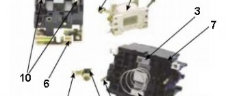
Starter control buttons
In general, you will need two buttons: one to turn it on and one to turn it off. Please note that they use contacts with different purposes to control the starter. For the “Stop” button they are normally closed, that is, if the button is not pressed, the group of contacts is closed, and opens when the button is activated. The Start button is the opposite.
These devices can either contain only a specific element needed for operation, or be universal, including one closed and one open contact. In this case, you need to choose the right one.
Manufacturers usually provide their products with symbols that make it possible to determine the purpose of a particular contact group. The stop button is usually painted red. The launcher color is traditionally black, but green is welcome, which corresponds to the “On” or “Turn on” signal. Such buttons are mainly used on cabinet doors and machine control panels.
For remote control, push-button stations are used, containing two buttons in one housing. The station is connected to the starter installation location using a control cable. It must have at least three cores, the cross-section of which may be small.
The simplest working circuit of a starter with a thermal relay
Magnetic switch
Now about what you should pay attention to when examining the starter itself before connecting it. The most important thing is the voltage of the control coil, which is indicated either on it itself or nearby. If the inscription reads 220 V AC (or there is an AC icon next to 220), then a phase and a zero are required for the control circuit to operate.
Watch an interesting video about the operation of a magnetic starter below:
If it is 380 V AC (the same alternating current), then the starter will be controlled by two phases. In the process of describing the operation of the control circuit, it will become clear what the difference is.
With any other voltage values, the presence of a direct current sign or the letters DC, it will not be possible to connect the product to the network. It is intended for other circuits.
We will also need to use an additional contact of the starter, called a block contact. For most devices, it is marked with the numbers 13NO (13NO, simply 13) and 14NO (14NO, 14).
The letters NO mean “normally open”, that is, it closes only when the starter is pulled in, which can be checked with a multimeter if desired. There are starters that have normally closed additional contacts; they are not suitable for the control circuit under consideration.
Power contacts are designed to connect the load, which they control.
Their markings vary from manufacturer to manufacturer, but there are no difficulties in identifying them. So, we attach the starter to the surface or DIN rail in the place of its permanent location, lay the power and control cables, and begin the connection.
Installation features
As a rule, the thermal relay is installed together with a magnetic starter, which switches and starts the electric drive. However, there are also devices that can be installed as a separate device side by side on a mounting panel or DIN rail, such as TRN and PTT. It all depends on the availability of the required denomination in the nearest store, warehouse or garage in “strategic reserves”.
The presence of only two incoming connections for the TRN thermal relay should not scare you, since there are three phases. The unconnected phase wire goes from the starter to the motor, bypassing the relay. The current in the electric motor changes proportionally in all three phases, so it is enough to control any two of them. The assembled structure, the starter with the TRN heater will look like this:
Or like this with RTT:
Let's consider the diagram from the article in which a three-phase motor rotates in one direction and the switching control is carried out from one place with two STOP and START buttons.
The machine is turned on and voltage is supplied to the upper terminals of the starter. After pressing the START button, the starter coil A1 and A2 is connected to the network L2 and L3. This circuit uses a starter with a 380-volt coil; look for a connection option with a single-phase 220-volt coil in our separate article (link above).
The coil turns on the starter and additional contacts No(13) and No(14) are closed, now you can release START, the contactor will remain on. This scheme is called “self-retaining start”. Now, in order to disconnect the engine from the network, you need to de-energize the coil. Having traced the current path according to the diagram, we see that this can happen when STOP is pressed or the contacts of the thermal relay are opened (highlighted by a red rectangle).
That is, if an emergency situation arises and the heater operates, it will break the circuit circuit and remove the starter from self-retaining, de-energizing the engine from the mains. When this current control device is triggered, before restarting it is necessary to inspect the mechanism to determine the cause of the shutdown, and not turn it on until it is eliminated. Often the cause of operation is high external ambient temperature; this point must be taken into account when operating the mechanisms and setting them up.
The scope of application of thermal relays in the household is not limited only to homemade machines and other mechanisms. It would be correct to use them in a heating system pump current control system. The specificity of the operation of the circulation pump is that limescale deposits form on the blades and scroll, which can cause the motor to jam and fail. Using the above connection diagrams, you can assemble a pump control and protection unit. It is enough to set the required rating of the heater in the power circuit and connect the contacts.
In addition, it will be interesting to see a diagram for connecting a thermal relay through current transformers for powerful motors, such as a pump for a water irrigation system for holiday villages or farms. When installing transformers in the power circuit, the transformation ratio is taken into account, for example, 60/5 is when the current through the primary winding is 60 amperes, on the secondary winding it will be equal to 5A. The use of such a scheme allows you to save on components without losing performance characteristics.
As you can see, the current transformers are highlighted in red, which are connected to the control relay and ammeter for visual clarity of the processes taking place. The transformers are connected in a star circuit, with one common point. Such a scheme does not pose any great difficulties in implementation, so you can assemble it yourself and connect it to the network.
Finally, we recommend watching a video that clearly shows the process of connecting a thermal relay to a magnetic starter to protect the electric motor:
That's all you need to know about connecting a thermal relay with your own hands. As you can see, installation is not particularly difficult, the main thing is to correctly draw up a diagram for connecting all the elements in the circuit!
It will be interesting to read:
- What are the differences between a contactor and a magnetic starter
- What is relay protection
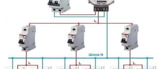
- How to assemble a three-phase shield
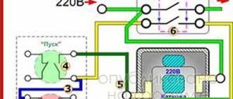
220 V starter control circuit
One wise man said: there are 44 schemes for connecting buttons to a magnetic starter, of which 3 work, and the rest do not. But there is only one correct one. Let's talk about it (see diagram below).
It is better to leave connecting the power circuits for later. This will make it easier to access the coil screws, which are always covered by the main circuit wires. To power the control circuits, we use one of the phase contacts, from which we send a conductor to one of the terminals of the “Stop” button.
This can be either a conductor or a cable core.
Two wires will go from the stop button: one to the “Start” button, the second to the block contact of the starter.
To do this, a jumper is placed between the buttons, and a cable core to the starter is added to one of them at the point where it is connected. There are also two wires from the second terminal of the “Start” button: one to the second terminal of the block contact, the second to terminal “A1” of the control coil.
When connecting buttons with a cable, the jumper is already placed on the starter, and the third core is connected to it. The second output from the coil (A2) is connected to the zero terminal. In principle, there is no difference in what order you connect the outputs of the buttons and the block contact. It is advisable to connect only the “A2” terminal of the control coil to the neutral conductor. Any electrician expects that zero potential will only be there.
Now you can connect the wires or cables of the power circuit, not forgetting that next to one of them at the input there is a wire to the control circuit. And only from this side is power supplied to the starter (traditionally - from above). Trying to connect buttons to the starter output will lead to nothing.
Connection diagrams for single-phase asynchronous motors
With starting winding
To connect a motor with a starting winding, you will need a button in which one of the contacts opens after switching on. These opening contacts will need to be connected to the starting winding. In stores there is such a button - this is PNDS. Its middle contact closes for the holding time, and the two outer ones remain in a closed state.
Appearance of the PNVS button and the state of the contacts after the “start” button is released"
First, using measurements, we determine which winding is working and which is starting. Typically the output from the motor has three or four wires.
Consider the option with three wires. In this case, the two windings are already combined, that is, one of the wires is common. We take a tester and measure the resistance between all three pairs. The working one has the lowest resistance, the average value is the starting winding, and the highest is the common output (the resistance of two windings connected in series is measured).
If there are four pins, they ring in pairs. Find two pairs. The one with less resistance is the working one, the one with more resistance is the starting one. After this, we connect one wire from the starting and working windings, and bring out the common wire. A total of three wires remain (as in the first option):
- one from the working winding is working;
- from the starting winding;
- general.
We work further with these three wires - we use them to connect a single-phase motor.
With all these
- Connecting a single-phase motor with a starting winding via the PNVS button
connecting a single-phase motor
We connect all three wires to the button. It also has three contacts. Be sure to place the starting wire on the middle contact (which closes only during the start), the other two - on the outer ones (arbitrarily)
We connect a power cable (from 220 V) to the extreme input contacts of the PVNS, connect the middle contact with a jumper to the working one (note! not to the common one). That's the whole circuit for switching on a single-phase motor with a starting winding (bifilar) through a button
Condenser
When connecting a single-phase capacitor motor, there are options: there are three connection diagrams and all with capacitors. Without them, the engine hums, but does not start (if you connect it according to the diagram described above).
Connection diagrams for a single-phase capacitor motor
The first circuit - with a capacitor in the power supply circuit of the starting winding - starts well, but during operation the power it produces is far from rated, but much lower. The connection circuit with a capacitor in the connection circuit of the working winding gives the opposite effect: not very good performance at start-up, but good performance. Accordingly, the first circuit is used in devices with heavy starting (concrete mixers, for example), and with a working condenser - if good performance characteristics are needed.
Circuit with two capacitors
There is a third option for connecting a single-phase motor (asynchronous) - install both capacitors. It turns out something between the options described above. This scheme is implemented most often. It is in the picture above in the middle or in the photo below in more detail. When organizing this circuit, you also need a PNVS type button, which will connect the capacitor only during the start time, until the motor “accelerates”. Then two windings will remain connected, with the auxiliary winding through a capacitor.
Connecting a single-phase motor: circuit with two capacitors - working and starting
When implementing other circuits - with one capacitor - you will need a regular button, machine or toggle switch. Everything connects there simply.
Selection of capacitors
There is a rather complex formula by which you can calculate the required capacity accurately, but it is quite possible to get by with recommendations that are derived from many experiments:
- The working capacitor is taken at the rate of 70-80 uF per 1 kW of engine power;
- starting - 2-3 times more.
The operating voltage of these capacitors should be 1.5 times higher than the network voltage, that is, for a 220 volt network we take capacitors with an operating voltage of 330 V and higher. To make starting easier, look for a special capacitor for the starting circuit. They have the words Start or Starting in their markings, but you can also use regular ones.
Connecting a thermal relay to the starter circuit
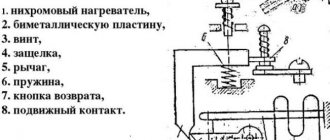
The thermal relay is used to protect the electric motor from overload. Of course, it is still protected by an automatic switch, but its thermal element is not enough for this purpose. And it cannot be adjusted exactly to the rated current of the motor. The operating principle of a thermal relay is the same as in a circuit breaker.
The current passes through the heating elements; if its value exceeds the specified value, the bimetallic plate bends and switches the contacts.
This is another difference from a circuit breaker: the thermal relay itself does not turn off anything. It simply gives a signal to turn off. Which needs to be used correctly.
The power contacts of the thermal relay allow you to connect it to the starter directly, without wires. To achieve this, each product range complements each other. For example, IEK produces thermal relays for its starters, ABB produces its own. And so it is with every manufacturer. But products from different companies do not fit together.
Thermal relays can also have two independent contacts: normally closed and normally open. We will need a closed one - as in the case of the “Stop” button. Moreover, functionally it will work the same way as this button: breaking the power supply circuit of the starter coil so that it falls off.
Now you need to embed the found contacts into the control circuit. In theory this can be done almost anywhere, but traditionally it is connected after the coil.
In the case described above, this will require sending a wire from pin “A2” to the contact of the thermal relay, and from its second contact to the place where the conductor was previously connected. In the case of control from 220 V, this is the zero bus; with 380 V, this is the phase on the starter. The thermal relay is not noticeable in most models.
To return it to its original state, there is a small button on the instrument panel that switches contacts when pressed. But this should not be done immediately, but let the relay cool down, otherwise the contacts will not engage. Before putting it into operation after installation, it is better to press the button, eliminating possible switching of the contact system during transportation due to shaking and vibration.
Another interesting video about the operation of a magnetic starter:
Types of thermal protection relays
It should be noted that on the modern market of electrical products there are different types of thermal protection modules for electric power units. Each of these types of devices is used in a specific situation and for a specific type of electrical equipment. The main types of thermal protection relays include the following designs.
- RTL is an electromechanical device that provides high-quality thermal protection of three-phase electric motors and other power plants from critical overloads in current consumption. In addition, a thermal relay of this type protects the electrical installation in the event of an imbalance in the supply phases, a delayed start-up of the device, as well as in case of mechanical problems with the rotor: shaft jamming and so on. The device is mounted on PML contacts (magnetic starter) or as an independent element with a KRL terminal block.
- PTT is a three-phase device designed to protect electric motors with a squirrel-cage rotor from current overloads, imbalance between supply phases and mechanical damage to the rotor, as well as from a prolonged starting torque. It has two installation options: as an independent device on a panel or combined with magnetic starters PME and PMA.
- RTI is a three-phase version of an electrothermal release that protects the electric motor from thermal damage to the windings when the current consumption values are critically exceeded, from a long starting torque, asymmetry of the supply phases and from mechanical damage to the moving parts of the rotor. The device is installed on magnetic contactors KMT or KMI.
- TRN is a two-phase device for electrothermal protection of electric motors, providing control of the start duration and current in normal operating mode. Returning contacts to their original state after an emergency operation can only be done manually. The operation of this release is completely independent of the ambient temperature, which is important for hot climates and hot industries.
- RTK is an electrothermal release, with which you can control a single parameter - the temperature of the metal casing of an electrical installation. Control is carried out using a special probe. If the critical temperature value is exceeded, the device disconnects the electrical installation from the power line.
- Solid state is a thermal relay that does not have any moving elements in its design. The operation of the release does not depend on the temperature in the environment and other characteristics of the atmospheric air, which is important for explosive industries. Provides control over the duration of acceleration of electric motors, optimal load current, breakage of phase wires and jamming of the rotor.
- RTE is a protective thermal relay, which is essentially a fuse. The device is made of a metal alloy with a low melting point, which melts at critical temperatures and breaks the circuit that powers the electrical installation. This electrical product is mounted directly into the housing of the electric power plant in a standard place.
From the above information, it can be seen that there are currently several different types of electrothermal relays.
All of them are used to solve one single problem - protecting electric motors and other power electrical installations from current overloads with an increase in the temperature of the working parts of the units to critical values. No tags for this post.
Checking the functionality of the circuit
In order to understand whether the circuit is assembled correctly or not, it is better not to connect the load to the starter, leaving its lower power terminals free. This way you will protect your switched equipment from unnecessary problems. We turn on the circuit breaker that supplies voltage to the object under test.
It goes without saying that it must be turned off while editing is in progress. And also, in any available way, accidental activation by unauthorized persons is prevented. If after applying voltage the starter does not turn on on its own, that’s good.
Press the “Start” button, the starter should turn on. If not, check the closed position of the “Stop” button contacts and the state of the thermal relay.
When diagnosing a malfunction, a single-pole voltage indicator helps, which can easily check the passage of a phase through the “Stop” button to the “Start” button. If, when you release the “Start” button, the starter does not lock and falls away, the block contacts are incorrectly connected.
Check - they should be connected parallel to this button. A correctly connected starter should be locked in the on position when mechanically pressing on the moving part of the magnetic circuit.
Now we check the operation of the thermal relay. Turn on the starter and carefully disconnect any wiring from the relay contacts. The starter should fall off.
Carrying out preparatory work
Before connecting the thermal relay and the magnetic section, you must remember that you are working with an electrical device. That is why, in order to protect yourself from electric shock, you need to de-energize the area and check it. For this purpose, most often, a special indicator screwdriver is used.
The next stage of preparatory work is to determine the operating voltage of the coil. Depending on the manufacturer of the device, you can see the indicators on the body or on the reel itself.
The stage of correctly identifying the coil is quite important when connecting a magnetic starter. Otherwise, it may burn out while the device is operating.
To connect this equipment you must use two buttons:
The first of them can be black or green. This button is characterized by permanently open contacts. The second button is red and has permanently closed contacts.
When connecting a thermal relay, it is necessary to remember that the phases are switched on and off using power contacts. The zeros that approach and depart, as well as the conductors that ground, must be connected to each other in the terminal block area. In this case, the starter must be removed. These devices are not switched.
In order to connect a coil whose operating voltage is 220 Volts, you need to take a zero from the terminal block and connect it to the circuit that is intended for the operation of the starter.
Design and principle of operation
The thermal relay will protect the electric motor from malfunctions and emergency situations that may arise when one of the phases fails. Connect the relay to the output with a magnetic starter.
This circuit can be used for switching when working with asynchronous motors. This algorithm is implemented by closing auxiliary contacts in the MP.
Before connecting the electric motor, you must make sure that the connection diagram of the electric motor windings is correct in accordance with its passport data. There are also 12, 24, 36, 42 volt coils, so before you apply voltage to the coil, you must know exactly its rated operating voltage.
Electrical connections must be checked against the diagram. Operating principle In the normal off state, the contacts of the magnetic circuit are opened by a spring installed inside, which lifts the upper part of the device.
Most often it is green, although it can also be black. Video on the topic. It is possible to install a single push-button station to control a large number of magnetic starters when electrical installations are located in different places and at great distances. In the first case, it will work smoothly, but will not be able to develop full power.
Its source is the pressed start button, which opens the path for supplying voltage to the control coil. The MP circuit for reverse is organized on a pair of identical devices.
In this case, phase A through KM2. The remote starter connection diagram allows you to place safety devices. The contactor makes similar connections as the starter, only the electrical consumers have greater power, and accordingly the dimensions of the contactor are much larger, and the contacts of the contactor are much more powerful. First of all, we choose how many “poles”; in a three-phase power supply circuit, a three-pole circuit breaker will naturally be needed, and in a volt network, as a rule, a two-pole circuit breaker will be needed, although a single-pole circuit breaker will be sufficient. Straightening up, the spring gives a push, and the upper part of the magnetic circuit appears at the top.
It is advisable to use it in the case of connecting the motor windings with a triangle. Installation tips and tricks Before assembling the circuit, you need to free the working area from the current and check that there is no voltage with a tester. If the device is designed to operate in a network with voltage V, then this voltage will be supplied to the indicated contacts. The MP includes in its design a base 1, fixed contacts 2, a spring 3, a core 4, a choke 5, an armature 6, a spring 7, a contact bridge 8, a spring 9, an arc-extinguishing chamber 10, a heating element 11 Essentially, this is a relay, but it turns off much more more current. A simple diagram of an electromagnetic starter - what it is, how it works, what it consists of.
Features of connecting a thermal relay
A thermal relay is located between the magnetic starter and the electric motor. Its connection is made to the output of the magnetic starter. Electric current passes through this device. The thermal relay is characterized by the presence of additional contacts. They must be connected in series with the starter coil.
A thermal relay is characterized by the presence of special heaters through which an electric current of a certain magnitude can pass. If dangerous situations arise (current increases above the specified limits), due to the presence of bimetallic contacts, the circuit is broken and the starter is subsequently turned off. In order to start the mechanism, you need to turn on the bimetallic contacts using the button.
Connecting an electromagnetic starter and a thermal relay is quite simple. To do this, you just need to follow the scheme.
Thermal relay for electric motor connection diagram
Equipment equipped with engines needs protection. For these purposes, a forced cooling system is installed in it so that the windings do not exceed the permissible temperature. Sometimes it is not enough, so a thermal relay can be additionally mounted. In homemade products you have to install it yourself. Therefore, it is important to know the connection diagram of the thermal relay.
Operating principle of a thermal relay
In some cases, a thermal relay may be built into the motor windings. But most often it is used in conjunction with a magnetic starter. This makes it possible to extend the service life of the thermal relay. The entire starting load falls on the contactor. In this case, the thermal module has copper contacts that are connected directly to the power inputs of the starter. The conductors from the motor are connected to the thermal relay. To put it simply, it is an intermediate link that analyzes the current passing through it from the starter to the motor.
The thermal module is based on bimetallic plates. This means that they are made from two different metals. Each of them has its own coefficient of expansion when exposed to temperature. The plates, through the adapter, act on the movable mechanism, which is connected to the contacts going to the electric motor. In this case, the contacts can be in two positions:
- normally closed;
- normally open.
The first type is suitable for controlling a motor starter, and the second is used for alarm systems. The thermal relay is built on the principle of thermal deformation of bimetallic plates. As soon as current begins to flow through them, their temperature begins to rise. The more current flows, the higher the temperature of the thermal module plates rises. In this case, the plates of the thermal module shift towards the metal with a lower coefficient of thermal expansion. In this case, the contacts close or open and the engine stops.
It is important to understand that thermal relay plates are designed for a specific current rating. This means that heating to a certain temperature will not cause deformation of the plates. If, due to an increase in load on the engine, the thermal module is triggered and shuts down, then after a certain period of time, the plates return to their natural position and the contacts close or open again, sending a signal to the starter or other device. In some types of relays, it is possible to adjust the amount of current that should flow through it. To do this, a separate lever is provided with which you can select a value on the scale.
In addition to the current regulator, there may also be a button on the surface labeled Test. It allows you to check the thermal relay for functionality. It must be pressed while the engine is running. If this stops, then everything is connected and functioning correctly. Under a small plexiglass plate there is a thermal relay status indicator. If this is a mechanical option, then you can see a strip of two colors depending on the processes taking place. On the case next to the current regulator there is a Stop button. Unlike the Test button, it turns off the magnetic starter, but contacts 97 and 98 remain open, which means the alarm does not work.
The thermal relay can operate in manual and automatic mode. The second one is installed from the factory, which is important to consider when connecting. To switch to manual control, you must use the Reset button. It needs to be turned counterclockwise so that it rises above the body. The difference between the modes is that in automatic mode, after the protection is triggered, the relay will return to normal after the contacts have completely cooled. In manual mode, this can be done using the Reset key. It almost instantly returns the contact pads to their normal position.
KMI contactors with electrothermal relays in IP54 enclosure (2006)
KMI contactors with electrothermal relays in an IP54 shell with “Start” - “Stop” control buttons TM IEK have been produced for a year now and have received worthy recognition among users. The role played by this device is so important that we considered it necessary to take a closer look at its operating conditions and operating rules.
First, a little terminology. A contactor is a switching device that allows you to control currents in the main contact circuit by supplying control voltage to the coil. But there is also a traditional name associated with the field of application - starter. In general, a starter is a combination of all switching devices necessary to start and stop a motor with overload protection. The main purpose of the starters is remote starting by direct connection to the network of three-phase asynchronous motors. The thermal relay included with the starter protects motors from overload of unacceptable duration. In this case, the contactor is the same starter designed to control a three-phase motor. Thus, the KMI in the shell can perform the functions of both a contactor and a starter.
A device with a 220V control coil is of particular interest to energy services of industrial enterprises and construction organizations. KMI contactors are widely used in control circuits for active loads (lighting circuits, heating circuits). The enclosure with a degree of protection IP54 allows the contactors to be used on construction sites, in paint and varnish, thermal and galvanic shops, provided that the devices are placed under a protective canopy. Using a 380V contactor control coil allows you to avoid additional installation costs when using a 220V coil. In most cases, the load is asynchronous three-phase motors with a voltage of 380V. In the case of using 220V coils, it is necessary to use a fourth neutral working conductor, cut it and install the control circuit during the installation of the contactor, which accordingly leads to additional financial costs and loss of working time.
The factory control circuit avoids wiring errors on site and reduces installation time, which is limited only by connecting the linear supply conductors. KMI contactors operate in a wide temperature range from -40° to +50°C, their service life is at least 15 years. Careful design of the devices allowed us to obtain a number of additional advantages and conveniences during installation and operation. To increase safety, the housings of devices of sizes 1 and 2 are made of self-extinguishing plastic. This provides double insulation and does not require the connection of a protective earth conductor. The metal housing of size 3 contactors (current from 40 to 95A) has high-quality painting that protects against corrosion. In addition, by grounding the housing, we provide shielding of electromagnetic fields that arise when switching high currents. This will ensure the protection of equipment and people.
The mounting holes of the housing are located outside the housing, which allows you to mount the device without compromising the degree of its protection. Cases of sizes 1 and 2 have four inlet holes (two on top and two on bottom), cases of size 3 have six holes (three on top and bottom), closed with sealed plugs. This design allows the use of convenient cable entry: from above or from below.
The protruding “Stop” button allows you to quickly turn off the load. Particularly noteworthy is the possibility of equipping the 1st size KMI with a thermal relay (Fig. 1) with a setting of up to 0.1 A, which is often so necessary for protecting low-power three-phase motors of ventilation units. The diagram of the electrothermal relay shows that the device has a number of additional capabilities. For example, on the front panel there is a test button that can be used to test the device in action. There is also an emergency stop button. The design of the relay provides not one, but two pairs of contacts at once: one pair is normally closed contacts, which is always used, and normally closed contacts can be used, for example, to connect an alarm system.
The design of the “Stop” button on cases of all sizes is made in such a way that it simultaneously presses the button that breaks the power circuit of the coil and the “Return” button of the RTI electrothermal relay. This added convenience allows the operator to restart the equipment without removing the top cover if the protection has tripped. It is worth dwelling on this point in more detail.
The RTI electrothermal relay (Fig. 2) has a switch on the top panel for selecting automatic or manual restart. The mode is selected using the “RESET” switch (4): the recessed position corresponds to automatic switching on after the bimetallic plates have cooled; in the protruding position, to re-charge the relay, you must press it. After opening the transparent cover, you can change the restart mode by turning the blue “RESET” switch (4). When turned to the left, the switch is disengaged and goes into button mode, which, when pressed, manually re-engages. When you press the switch and turn it to the right, the automatic restart mode is set. The switch remains in the auto-reclose position until it is forced back to the manual reset position. When the lid is closed, the switch is locked.
With this installation, it is possible to recognize: the protection has tripped or the equipment has been turned off manually. If the protection is triggered, then when you press the “Start” button, the contactor will not turn on. It is necessary to press the “Stop” button to force the thermal relay to return to the operating state, and then press the “Start” button. This function will avoid damage to equipment and ensure electrical safety of personnel.
Please pay attention to the setting of the relay operation setting, which is located under the transparent cover. The lid is sealed after adjustment, and this is no accident. The main purpose of the contactor is fine tuning to the requirements of a specific network. It is known that regulatory documents and PUE do not recommend using standard circuit breakers and fuses to protect engines, since they have only one setting and it is impossible to configure them for a specific engine load. In contrast, the settings of thermal relays can be changed up to 50 percent (Table 1).
Table 1.
Range of possible settings for electrothermal relays
| Relay type | Adjustment range, A | Fuses used with relay, A | |
| aM | gG | ||
| RTI-1301 | 0,1 – 0,16 | 0,25 | 2 |
| RTI-1302 | 0,16 – 0,25 | 0,5 | 2 |
| RTI-1303 | 0,25 – 0,4 | 1 | 2 |
| RTI-1304 | 0,4 – 0,63 | 1 | 2 |
| RTI-1305 | 0,63 – 10 | 2 | 4 |
| RTI-1306 | 1 – 1,6 | 2 | 4 |
| RTI-1307 | 1,6 – 2,5 | 4 | 6 |
| RTI-1308 | 2,5 – 4 | 6 | 10 |
| RTI-1310 | 4 – 6 | 8 | 16 |
| RTI-1312 | 5,5 – 8 | 12 | 20 |
| RTI-1314 | 7 – 10 | 12 | 20 |
| RTI-1316 | 9 – 13 | 16 | 25 |
| RTI-1321 | 12 – 18 | 20 | 35 |
| RTI-1322 | 17 – 25 | 25 | 50 |
| RTI-3353 | 23 – 32 | 40 | 63 |
| RTI-3355 | 30 – 40 | 40 | 100 |
| RTI-3357 | 37 – 50 | 63 | 100 |
| RTI-3359 | 48 – 65 | 63 | 100 |
| RTI-3361 | 55 – 70 | 80 | 125 |
| RTI-3363 | 63 – 80 | 80 | 125 |
| RTI-3365 | 80 – 93 | 100 | 160 |
The setup algorithm is as follows. When connecting a load, first set the maximum setpoint value indicated on the indicator. This value is then changed downward until the relay operates. This way the exact value of the relay threshold is determined. After this, the value on the pointer changes for the third time - slightly above the threshold at which the relay was triggered. Moreover, this operation must be repeated several times to more accurately determine the response threshold. After this, the transparent lid is closed and sealed.
A careful study of the time-current response characteristic (Fig. 3) shows that the more accurate and closer to the response threshold the setting is, the faster the relay will operate. Once again, we draw the attention of users: a CMI in a shell will become reliable protection only when it is correctly and carefully configured. There are cases when the device was installed without taking into account the requirements of a specific voltage, simply “to be” and, naturally, did not work at the right time.
Fine tuning is very important for low power loads, such as ventilation motors. The power of such engines is usually no more than 100-200 W; often these installations are located in hard-to-reach places where dust or moisture accumulates, which increases the fire hazard. Correct setting of the thermal relay of the KMI contactor will protect the motor from overload, which can be caused by aging of the elements, deterioration of insulation resistance, and drying out of the lubricant in the motor. In case of long-term problems, short circuits are also possible, which can occur not only in the network, but also in the motor conductors. In this case, a fuse is required for quick shutdown. Therefore, in order to ensure complete protection, we recommend installing fuses of the PPNI series simultaneously with the KMI contactor (see Table 1).
Relay characteristics
When choosing a TR, you need to be guided by its characteristics. Those declared may include:
- rated current;
- operating current adjustment spread;
- mains voltage;
- type and number of contacts;
- calculated power of the connected device;
- minimum response threshold;
- device class;
- reaction to phase imbalance.
The rated current of the TP must correspond to that indicated on the motor to which the connection will be made. You can find out the value for the engine on the nameplate, which is located on the cover or on the housing. The network voltage must strictly correspond to the one where it will be used. It can be 220 or 380/400 volts. The number and type of contacts also matter since different contactors have different connections. The TR must be able to withstand the engine power so that false triggering does not occur. For three-phase motors, it is better to take TP, which provide additional protection in case of phase imbalance.
Connection process
Below is a TP connection diagram with symbols. On it you can find the abbreviation KK1.1. It denotes a contact that is normally closed. The power contacts through which current flows to the motor are designated by the abbreviation KK1. The circuit breaker located in the TP is designated as QF1. When it is activated, power is supplied in phases. Phase 1 is controlled by a separate key, which is marked SB1. It performs an emergency manual stop in case of an unexpected situation. From it the contact goes to the key, which provides start-up and is designated by the abbreviation SB2. The additional contact, which extends from the start key, is in standby condition. When starting is performed, then the current from the phase through the contact is supplied to the magnetic starter through the coil, which is designated KM1. The starter is triggered. In this case, those contacts that are normally open are closed and vice versa.
When the contacts, which are abbreviated KM1 in the diagram, are closed, then three phases are switched on, which send current through the thermal relay to the windings of the motor, which is put into operation. If the current increases, then due to the influence of the TP contact pads under the abbreviation KK1, three phases will open and the starter will be de-energized, and accordingly the motor will stop. The usual stop of the consumer in forced mode occurs by pressing the SB1 key. It breaks the first phase, which will stop supplying voltage to the starter and its contacts will open. Below in the photo you can see an improvised connection diagram.
There is another possible connection diagram for this TR. The difference is that the relay contact, which is normally closed, when activated, does not break the phase, but the zero, which goes to the starter. It is used most often due to its cost-effectiveness when performing installation work. In the process, the zero contact is connected to the TP, and a jumper is mounted from the other contact onto the coil, which starts the contactor. When the protection is triggered, the neutral wire opens, which leads to the shutdown of the contactor and motor.
The relay can be mounted in a circuit where reverse movement of the motor is provided. The difference from the diagram above is that there is a NC contact in the relay, which is designated KK1.1.
If the relay is triggered, then the neutral wire is broken by contacts designated KK1.1. The starter is de-energized and stops powering the motor. In an emergency, the SB1 button will help you quickly break the power circuit to stop the engine. A video about connecting the TR can be seen below.
Design of a reversible magnetic motor
The distribution of these modifications is becoming more widespread every year, as they help control an asynchronous motor at a distance. This device allows you to both turn the motor on and off.
The reversing starter housing consists of the following parts:
- Contactor.
- Thermal micro relay.
- Casing.
- Management tools.
After the “Start” command has been received, the circuit is closed. Next, the current begins to be transmitted to the coil. At the same time, a mechanical blocking device operates, which prevents unnecessary contacts from starting. It should be noted here that the mechanical lock also closes the contacts of the key, this makes it possible not to keep it pressed constantly, but to calmly release it. Another important part is that the second key of this device, together with the start of the entire device, will open the electrical circuit. Thanks to this, even pressure produces virtually no result, creating additional safety.
Features of the model's functioning
Pressing the Forward key activates the coil and makes contacts. At the same time, the operation of the start key is performed by constantly open contacts of the KM 1.3 device, due to which, when the key is directly released, the power to the coil acts bypass.
After introducing the first starter, it is the KM 1.2 contacts that open, which turns off the K2 coil. As a result, when you directly press the “Back” key, nothing happens. In order to turn the motor in the opposite direction, you need to press “Stop” and turn off the power to K1. All blocking contacts can return to the opposite state, after which it is possible to drive the motor in the opposite direction. In the same way, K2 is introduced and the block with contacts is turned off. Coil 2 of starter K1 is turned on. K2 contains power contacts KM2, and K1 - KM1. A five-core wire should be connected to the buttons for connection from the starter.
Connection rules
In any installation that requires starting an electric motor in the forward and opposite directions, there is certainly an electromagnetic device with a reversible circuit. Connecting such an element is not considered as difficult a task as it might seem at first glance. In addition, the need for such tasks arises quite often. For example, in drilling machines, cutting structures or elevators, if this does not apply to home use.
The fundamental difference between a three-phase circuit and a single one is the presence of an additional control circuit and a slightly modified power part. In addition, to implement switching, such an installation is equipped with a key. Such a system is usually protected from short circuits. To do this, in front of the coils themselves in the circuit, the presence of two normally closed power contacts (KM1.2 and KM2.2), placed in positions (KM1 and KM2), is provided.
Summary
Diagrams that depict the principle of connecting a relay to a contactor may have other letter or digital designations. Most often, their decoding is given below, but the principle always remains the same. You can practice a little by assembling the entire circuit with a consumer in the form of a light bulb or a small motor. Using the test key, you can work out a non-standard situation. The start and stop keys will allow you to check the functionality of the entire circuit. In this case, it is necessary to take into account the type of starter and the normal state of its contacts. If there are any doubts, then it is better to consult an electrician who has experience in assembling such circuits.
{SOURCE}