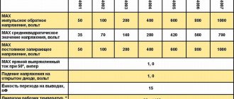
Thermal relay TRN-10, TRN-25
Two-pole thermal current relays TRN-10, TRN-25 with temperature compensation and currents from 0.5 to 25 A. Two-pole thermal current relays TRN-10 UHL4, TRN-25 UHL4 with temperature compensation, with rated currents of thermal elements from 0.5 up to 25 A are intended mainly for protection against unacceptable overloads of three-phase asynchronous electric motors with a squirrel-cage rotor, operating from a network with a rated voltage of up to 500 V at a frequency of 50-60 Hz.
The relays can be used in DC networks with a rated voltage of up to 440 V. The relays do not protect against short circuits and themselves require such protection.
Terms of Use:
– altitude above sea level up to 1000 m (work is allowed at altitudes up to 2000 m at a rated voltage of no more than 380 V at an ambient temperature of +1 to +40 ° C;
– relative air humidity at a temperature of +20 °C no more than 80% and no more than 50% at a temperature of +40 °C;
– frequency of vibration and fastening points is 25 Hz with an acceleration of no more than 0.7 g.
Relays are produced only in open versions and are not designed for operation in explosive environments, as well as in environments containing significant amounts of dust, aggressive gases and vapors in concentrations that destroy metals and insulation. The relays are installed in places protected from direct contact with water, oil, metal dust, etc., as well as outdoors in enclosures not exposed to solar radiation.
Intermediate relays of the RP21 series are used in control circuits of AC electric drives with voltage up to 240 V - for three- and four-contact relays, with voltage up to 380 V - for one- and two-contact relays, in DC circuits with voltage up to 220 V.
The relay consists of a contact system and an electromagnet. The contact system consists of fixed contacts on flat plates fixed in a plastic base, and movable contacts on flat springs fixed between plastic blocks on the electromagnet armature. The moving contacts are connected to the terminals by flexible connectors. . An electromagnet contains a magnetic circuit, a core, a coil and an armature. The magnetic core is attached to the plastic base with screws. . Soldering lamellas allow the connection of two copper conductors with a total cross-section of 1.5 mm2, screw terminals - two conductors from 0.5 to 1.5 mm2 each.
New-electro
Electrothermal relays TRN-10 UHL4 and TRN-25 UHL4
Purpose
Two-pole electrothermal relays with temperature compensation TRN-10 UHL4 and TRN-25 UHL4 are designed to protect electrical installations from overloads in long-term operation.
The relays are designed for operation in alternating current networks with a frequency of 50 and 60 Hz with voltages up to 500 V (TRN-10), 660 V (TRN-25) and direct current with voltages up to 440 V. The relays are manufactured in accordance with TU 16–523.600– 81 and are designed to operate in the following conditions:
- altitude above sea level up to 1000 m;
- work is allowed at altitudes up to 2000 m above sea level with a rated voltage of no more than 380 V;
- ambient temperature from plus 1 °C to plus 40 °C;
- relative humidity of the ambient air at a temperature of plus 20 °C is no more than 80% and no more than 50% at a temperature of plus 40 °C;
- the environment is not explosive, does not contain significant amounts of dust or aggressive gases and vapors in concentrations that destroy metals and insulation;
- absence of sharp shocks and shock shocks;
- working position in space - on a vertical plane with the control circuit clamps facing up;
- deviation - from the working position no more than 10° in any direction;
- vibration of the relay mounting points with a frequency of up to 25 Hz with an acceleration of no more than 0.7q. If the specified conditions are met, the relays do not operate when a non-operation current flows for a long time around both poles and operate within 20 minutes. after increasing the current by 20% for relays whose heaters are installed by the manufacturer and by 25% if the heaters are installed by the consumer. The values of rated non-operation currents are given in table. 1.
Table 1
| Relay type | Nom. relay current, A | Maximum continuous current regime | Rated failure current In, A | Recommended cross-section of conductive wires, mm² | |
| copper | aluminum | ||||
| TRN-10 UHL4 | 10 | 1.25 In | 0,5; 0,63; 0.8; 1,0; 1,25; 1,6; 2; 2.5; 3,2; 4; 5; 6,3; 8 | 1 | 2,5 |
| 1.00 In | 10 | ||||
| TRN-25 UHL4 | 25 | 1.25 In | 5; 6,3; 8 10 1,25 16 20 | 1 1,5 2,5 2,5 4,0 4,0 | 2,5 2,5 4,0 6,0 10 |
| 1.00 In | 25 | ||||
The relays have adjustment of the non-operation current within the limits of minus 25 plus 25% of the rated non-operation current. The failure current is adjusted using the setting regulator. Each division of the regulator scale corresponds to 5% of the rated non-operation current. When the regulator is set to position “O”, the rated non-operation current is equal to the rated current of the heater.
When the regulator is set to the “+” position, the failure current increases, and when the regulator is set to the “-” position, it decreases in relation to the value of the rated failure current. When the ambient temperature deviates from plus 20 °C, the value of the failure current practically does not change. When a sixfold non-operation current flows around the relay from a cold state at an ambient temperature of plus 20 °C, the relay operates within the range from 6 to 25 s. The relays are supplied with heaters installed in them, the rated currents of which are specified when ordering. Power consumed by one pole: → relay TRN-10 - 5.4 W; → relay TRN-25 - 6.25 W.
Relays have manual reset only. When the relay is triggered, a return can be made after 2 minutes. The relays have one break contact, which allows disconnection and long-term flow of the currents indicated in the table. 2 with an inductive load having a power factor of at least 0.3 at an alternating current frequency of 50 and 60 Hz and a time constant of not more than 0.05 s. at constant current.
| Switching current | Rated continuous current, A | |
| variable | constant | |
| 3A at 380V 1A at 660V | 4 A; 24 V 0.6 A; 110 V 0.3 A; 220 V 0.12 A; 440 V | 6 |
Before putting into operation, during operation of the relay and after a long break in operation, it is necessary to check the integrity of all parts and assemblies of the relay, check the tightness of the screws, and remove dust. The moving relay system must move without chafing or jamming.
When replacing heaters on relays, they must be secured first to the rear lamellas, and then to the plane of the front lamellas. Bending and bulging of heaters is not allowed.
The calibration screws must not be rotated.
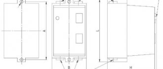
Overall and installation dimensions of the relay are shown in Fig. 1.
Relay TRN-254 UHL4 I - setpoint regulator, II - return button.
Rice. I. In Fig. 1 relay is shown in operating position.
The weight of the TRN-10UHL4 relay is 280 g.
The weight of the TRN-25UHL4 relay is 350 g.
Related materials:
- Checking, adjusting and setting up thermal relays type TRN, TRP
Electrothermal relay TRN-25 UHL4
Two-pole electrothermal relays with temperature compensation TRN25 UHL4 are designed to protect electrical installations from overloads in long-term operation. The relays are designed for operation in alternating current networks with a frequency of 50 and 60 Hz with voltages up to 500 V (TRN-10), 660 V (TRN-25 ) and direct current for voltages up to 440 V.
The relays have adjustment of the non-operation current within the range of minus 25 plus 25% of the rated non-operation current.
The failure current is adjusted using the setting regulator. Each division of the regulator scale corresponds to ?5% of the rated non-operation current.
When the regulator is set to position “O”, the rated non-operation current is equal to the rated current of the heater. When the regulator is set to the “+” position, the failure current increases, and when the regulator is set to the “-” position, it decreases in relation to the value of the rated failure current.
When the ambient temperature deviates from plus 20°C, the value of the failure current practically does not change.
When a six-fold non-operation current flows around the relay from a cold state at an ambient temperature of plus 20°C, the relay operates within 6 to 25 s.
The relays are supplied with heaters installed in them, the rated currents of which are specified when ordering. The power consumed by one pole of the TRN-10 relay is 5.4 W, the TRN-25 relay is 6.25 W.
Relays have manual reset only. When the relay is triggered, a return can be made after 2 minutes.
The relays have one break contact, which allows disconnection and long-term flow of the currents indicated in the table. 2 with an inductive load having a power factor of at least 0.3 at an alternating current frequency of 50 and 60 Hz and a time constant of not more than 0.05 s. at constant current.
Thermal relay TRN
Two-pole thermal relays TRN-10, TRN-25 – protect against overloads and phase breaks in circuits with direct voltage up to 400V and alternating voltage up to 660V, rated current load up to 25A and current settings range from 0.37-0.63A to 18- 32A. The operation of the TRN relay is based on the properties of bimetallic elements to change their shape when heated, resulting in a break in the contact circuit. TRN relays are used with PME and PAE starters. Degree of protection – IP00.
Features of the TRP relay.
This type of device is suitable for use under conditions of increased mechanical stress. It has a shock-resistant case and vibration-resistant mechanism. The sensitivity of the automation element does not depend on the ambient temperature, since the response point lies beyond the limit of 200 degrees Celsius. Mainly used with asynchronous motors of three-phase power supply (current limit - 600 amperes and power supply - up to 500 volts) and in DC circuits up to 440 volts. The relay circuit provides a special heating element for transferring heat to the plate, as well as smooth adjustment of the bend of the latter. Due to this, you can change the operating limit of the mechanism up to 5%.
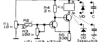
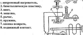
A thermal relay in magnetic starters is installed to protect the electric motor from overloads. The thermal relay consists of four main elements: heater 1, connected in series to a circuit protected from overload; bimetallic plate 2 of two pressed metal plates with different linear expansion coefficients; systems of 3-7 levers and springs; contacts 8 and 9. Thermal relay diagram. 1 - heater; 2 - bimetallic plate; 3 - adjusting screw; 4 - latch; 5 — lever; 6 - spring; 7 — return button; 8 - moving contact; 9 - fixed contact; 10 — heater output
When a current exceeding the rated current of the electric motor passes through the heating element 1, such an amount of heat is released that the loose (in the figure left) end of the bimetallic plate 2 bends towards the metal with a lower linear expansion coefficient (that is, it lowers), presses on the adjusting screw 3 and disengages latch 4. At this moment, under the action of spring 6, the upper end of lever 5 will rise, open contacts 8 and 9 and break the control circuit of the magnetic starter. Button 7 is used to manually return lever 5 to its original position after the relay is activated. From the above it follows that the operation of a thermal relay is based on the bending of a bimetallic plate under the influence of the heat generated in the heating element. But this same plate will also bend under the influence of the heat of the surrounding air. Thus, on hot days the relay will operate faster than on cold days. To eliminate this phenomenon, the relay uses temperature compensation, the essence of which is that the bending of the bimetallic plate due to changes in ambient temperature corresponds to the bending of the compensator plate in the opposite direction. The compensator plate is also a bimetallic plate, but with a deflection opposite to the main bimetallic plate. Thermal relays TRN are built into magnetic starters of the PME-100, PME-200 types and into magnetic starters PAE-300. These relays are two-phase, temperature compensated, with manual reset. The heating of the bimetal is indirect, the heaters are replaceable with a rated current of up to 40 A. The temperature compensator is made of bimetal with a reverse deflection in relation to the main thermoelement. At a steady temperature, a certain gap is established between the compensator and the latch. Changing the size of this gap by turning the eccentric (setpoint adjuster), i.e. Removing or approaching the latch changes the relay setting. Each division of the setpoint regulator corresponds to 5% of the rated current of the heater. When the regulator is set to position “O”, the relay setting current is equal to the rated current of the heater. When the regulator is set to position “-5”, the set current decreases by 25%, when set to position “+5” it increases by 25% in relation to the rated current of the heater. The relay response time at an ambient temperature of 20±5°C and when the relay is heated from a cold state by six times the rated current of the setting at any position of the set control should be within the following limits:
Design of thermal relay TRN-10: 1, 2, 3, 4, 6 - screws; 5 - cover; 7 - heating element; 8 — plastic cover; 9 — rod; 10 - contact bridge
- 3-15 s - for relay TRN-10 A;
- 6—25 s — for relays of types TRN-10; TRN-25 and TRN-40.
The manual reset time of the relay within the ambient temperature range from -40 to +60°C should be no more than 2 minutes. When installing the relay in the operating position at an ambient temperature of 20 ± 5 ° C and a rated current flowing around both poles, the relay should not operate in a steady thermal state and should operate within no more than 20 minutes at a current equal to 1.2 rated current of the setting. The protective characteristics of the relay are shown in Fig. 2.16 and 2.17. Single-phase thermal relays TRP-60 and TRP-150 (Fig. 2.18), built into PAE starters of the fourth, fifth and sixth magnitudes, have combined heating of the bimetallic plate (one part of the current passes through the heating element, the other through the bimetallic plate). With one heater designed for zero set current, it is possible to adjust the set current within ±25%. The relay has a scale with five divisions on either side of zero. The division price is 5% for open execution and 5.5% for protected execution. The TRP thermal relay has two return options: manual return with guaranteed non-self-reset of the contact group and self-reset with manual return acceleration. The relay does not operate when there is a long-term flow of current equal to the set current; triggers within 20 minutes after the current increases by 20% compared to the set current. The relay operates normally at currents not exceeding 15 times the value. The relay allows a load of 18 times the rated current of the thermal element for 1 s, or until the relay operates if it occurs in less than 1 s.
Multiplicity of operating current in relation to the installation current
Protective characteristics of the TRN-25 and TRN-40 relays 1 - zone of protective characteristics when the relay is activated from a cold state; 2 - zone of protective characteristics when the relay is activated from a hot state (after warming up) Multiplicity of the operation current in relation to the installation current
Protective characteristics of the TRN-10A relay 1 - zone of protective characteristics when the relay is activated from a cold state; 2 - zone of protective characteristics when the relay is activated from a hot state (after warming up)
Thermal relays type TRP: 1 - bimetallic plate; 2 — self-return stop; 3 — movable contact holder; 4 - spring; 5 - moving contact; 6 - fixed contact; 7 - replaceable heater; 8 — setting current regulator; 9 - manual return button
To protect the TRP-60 and TRP-150 relays from short circuit currents, it is sufficient that the rated current of the fuse insert connected in series with the thermal element of the protected relay exceeds the rated current of the thermal element by no more than 4-5 times.
Thermal relay. Device, principle of operation, circuit diagram for switching on a thermal relay.
Rice. 1.1. Design diagram of a thermal relay type TRP:
1 - bimetallic plate; 2 - heating element; limiting projections; 4 - spring; 5 - fixed contact; 6 - jumping contact
Rice. 1.2. Thermal relay TRP
: 1 - bimetallic plate; 2 — self-return stop; 3 — movable contact holder; 4 - spring; 5 - moving contact; 6 - fixed contact; 7 - replaceable heater; 8 — setting current regulator; 9 - manual return button
TRP series relays for currents of 1-600 A are mainly used in PA series magnetic starters and have a combined heating system. An exception is the TRP-600 relay (Fig. 1.2).
Bimetallic plate 1 is heated both by the passage of current through it and by heater 7. When deflected, the end of the bimetallic plate acts on the jumping movable contact 5. The relay allows smooth manual adjustment of the operating current within ± 25% of the rated current setting. This adjustment is carried out by handle 8, which changes the initial deformation of the bimetallic plate. The relay is returned to its original position after operation by button 9. It is also possible to design it with self-return after the bimetal has cooled. High operating temperature (above 200 °C) reduces the dependence of the relay operation on the ambient temperature.
RT series relays are open-design devices with an indirect heating system. Regulation of the operating current of the RT relay within small limits is carried out using a lever, the movement of which changes the stroke of the end of the bimetallic plate when heated until the latch is released. Wider regulation of the actuation current is carried out by replacing the heating elements. There are 56 numbers of heating elements for 0.64-40 A.
The TRV relay is used to protect engines with easy starting conditions; 20 versions are available for currents up to 200 A.
TRN series relays are produced for currents of 0.5-40 A with temperature compensation. They are mainly used in magnetic starters of the PME and PA series; they are indirectly heated using nichrome plate heaters.
Figure 1.3 shows a design diagram of a thermal relay TRN, intended for magnetic starters of the PME and PMA types (Table 1.2). The bimetallic plate 2, when passing a current exceeding the specified one, bends and moves the plastic pusher 11 to the right, which is rigidly connected to the bimetallic plate 3, which acts as a temperature compensator. Deflecting to the right, plate 3 presses on latch 8 and disengages it from the plastic setting motor 5, as a result of which, under the action of spring 10, the plastic release rod 7 moves upward (shown in dotted lines) and opens contacts 9 in the magnetic starter control circuit. The settings slider can be moved by turning the eccentric 4 and changing the distance between the ends of the plate 3 and the latch 8, and therefore the relay operating current.
Temperature compensation consists in the fact that the bending of the bimetallic plate 2 when the environment changes corresponds to the bending of the compensator plate 3, which is opposite in direction. In this way, the independence of the set current from the ambient temperature is achieved. The setting current can be changed in the range from 0.75 to 1.3 rated current of the heating element.
Rice. 1.3. Design diagram of a thermal relay type TRN:
1 - heating element;
2 - bimetallic plate; 3 - bimetallic plate of the temperature compensator; 4 - eccentric; 5 — setting slider; 6 — “Return” button; 7 — release rod (rod); 8 - latch; 9 — contacts; 10 - spring; 11 - pusher Table 1.2 Values of rated currents of replaceable heating elements of thermal relays of the TRN and TRP types
| Relay | Maximum value of load In (A) | In of replaceable heating elements, A |
| TRN-10A | 3,2 | 0,31; 0,4; 0,5; 0,63; 0,8; 1,1; 1,25; 1,6; 2,0; 2,5; 3,2 |
| TRN-10 | 10 | 0,5; 0,63; 0,8; 1,0; 1,25; 1,6; 2; 2,5; 3,2; 4,5; 6,3; 8; 10 |
| TRN-25 | 25 | 5; 6,3; 8; 10; 12,5; 16; 20; 25 |
| TRN-40 | 40 | 12,5; 16; 20; 25; 32; 40 |
| TRP-25 | 25 | 1; 1,2; 1,5; 2; 2,5; 3; 4; 5; 6; 8; 10; 12; 15; 20 |
| TRP-60 | 60 | 20; 25; 30; 40; 50; 60 |
In agriculture, more advanced three-pole thermal relays of the RTL (Table 1.3) and RTT (Table 1.4) types are used.
Table 1.3 Adjustment ranges and maximum values of rated currents (1N) of RTL type relays
| Thermal relays | Maximum value of In at ambient temperature +40 °C, A | Adjustment range In, A | Thermal relays | Maximum value of In at ambient temperature +40 °C, A | Adjustment range In, A |
| 1 | 2 | 3 | 4 | 5 | 6 |
| RTL-100104 | 0,17 | 0,1-0,17 | RTL-102104 | 19 | 13-19 |
| RTL-100204 | 0,26 | 0,16-0,26 | RTL-102204 | 25 | 18-25 |
| RTL-100304 | 0,4 | 0,24-0,4 | RTL-205304 | 30 | 23-32 |
| RTL-100404 | 0,65 | 0,38-0,65 | RTL-205504 | 40 | 30-41 |
| RTL-100504 | 1,0 | 0,61-1,0 | RTL-205704 | 50 | 38-52 |
| RTL-100604 | 1,6 | 0,95-1,6 | RTL-205904 | 57 | 47-64 |
| RTL-100704 | 2,6 | 1,5-2,6 | RTL-206104 | 66 | 54-74 |
| RTL-100804 | 4,0 | 2,4-4,0 | RTL-206304 | 80 | 63-86 |
| RTL-101004 | 6,0 | 3,8-6,0 | RTL-310504 | 105 | 75-105 |
| RTL-101204 | 8,0 | 5,5-8,0 | RTL-312504 | 125 | 90-125 |
| RTL-101404 | 10 | 7,0-10 | RTL-326004 | 160 | 115-160 |
| RTL-101604 | 14 | 9,5-14 | RTL-320004 | 200 | 145-200 |
Table 1.4 Maximum values of Iн, range of their adjustment Iн of replaceable heating elements of thermal relays PTT
| Relay | Maximum value of In, A | Adjustment range In, A | In of replaceable heating elements, A |
| RTT-11, RTT-12* | 10 | 0,85-1,15 | 0,2; 0,25; 0,32; 0,4; 0,5; 0,63; 0,8; 1,0; 1,25; 1,6; 2,0; 2,5; 3,2; 4; 6,3; 8; 10 |
| RTT-21, RTT-22* | 63 | 0,85-1,15 | 6,3; 8; 10; 12,5; 16; 20; 25; 32; 40; 50; 63 |
| RTT-31, RTT-31* | 160 | 0,85-1,15 | 63; 80; 100; 125; 160 |
*These modifications are installed only in magnetic starter boxes.
Thermal relays type RTL
have: three poles; temperature compensator; mechanism for accelerated response in case of phase failure; failure current regulator; manual return; one NC and one NO contact; front connection of wires; non-replaceable heating elements.
Thermal relays RTE are produced in three standard sizes, with a current range of the thermal release setting from 0.4 to 93 A. The presence of two pairs of additional contacts, normally closed and normally open, greatly facilitates the design of control circuits. These contacts can be used both for device self-diagnosis and for command circuits. Current adjustment ranges for RTE type relays are given in Table 1.5.
Only correctly adjusted thermal relays can protect electric motors from overloads. Therefore, let's consider methods for adjusting the relay
. The thermal relay adjustment settings can be determined by calculation in the following sequence:
1. Determine the relay setting without temperature compensation:
N1 = (In dv – Ine)/cIne, (1.1)
where In dv is the rated load current of the electric motor;
Ine is the rated current of the heating element of the thermal relay;
c is the scale division coefficient (c = 0.05).
2. Calculate the correction for ambient temperature:
N2 = (T – 30)/10, (1.2)
where T is the ambient temperature, °C.
3. The amendment is necessary in cases where the ambient temperature is below the maximum (40 °C) by more than 10 °C. If the ambient temperature changes significantly (winter and summer), the thermal relay should be adjusted again. Find the total relay setting:
N = N1 + N2, (1.3)
which can be with a “+” or “-” sign.
Then, on the resulting scale division, set the arrow of the adjusting screw or lever. Table 1.5 Appearance and current adjustment ranges of RTE type relays
| Image | Name | Adjustment range, A | Rated operating voltage Ue, V |
| RTE-1304 | 0.4-0,63 | 660 | |
| RTE-1305 | 0,63-1 | ||
| RTE-1306 | 1-1,6 | ||
| RTE-1307 | 1,6-2,5 | ||
| RTE-1308 | 2,5-4 | ||
| RTE-1310 | 4-6 | ||
| RTE-1312 | 5,5-8 | ||
| RTE-1314 | 7-10 | ||
| RTE-1316 | 9-13 | ||
| RTE-1321 | 12-18 | ||
| RTE-1322 | 17-25 | ||
| RTE-2353 | 23-32 | 660 | |
| RTE-2355 | 30-40 | ||
| RTE-3353 | 23-32 | 660 | |
| RTE-3355 | 30-40 | ||
| RTE-3357 | 37-50 | ||
| RTE-3359 | 48-65 | ||
| RTE-3361 | 55-70 | ||
| RTE-3363 | 63-80 | ||
| RTE-3365 | 80-93 |
Often electric motors and their starting protection equipment are located in different temperature conditions, for example, the electric motor is installed inside the livestock building, and the starting protection equipment is installed outside. In these cases, it is almost impossible to correctly adjust the thermal relay.
By adjusting the setting obtained as a result of calculating the scale divisions, it is possible to approximately adjust the thermal relays. For their precise adjustment, special devices are used - stands.
In agricultural production, electric motors with a power of up to 30 kW are mainly used. To protect them, various thermal relays are used, which are regulated using a device that creates a load current in the range of 0-50 A.
Figure 1.4 shows a schematic diagram of a laboratory bench for testing and adjusting thermal relays. Such a stand can be successfully manufactured on-farm. The heating elements of thermal relays (KK1 and KK2) are connected to the secondary winding of the low-power load transformer TV2. The voltage of the primary winding is smoothly regulated by a laboratory autotransformer (LATR) TV1. The load current of the thermal relay KK1 is recorded by an ammeter pA (Fig. 1.4, a).
The load current of relay KK2 is recorded by an ammeter pA connected to the secondary circuit through a current transformer TI (Fig. 1.4, b).
Since transformer TV2 is loaded with low resistance of the heating element of the thermal relay and a large current flows in the secondary circuit, the secondary winding of the transformer must be made of a large-section wire designed for a load current of 50 A. The number of turns of the secondary winding of the load transformer is selected from the condition that it is necessary to obtain sufficient voltage to regulate low-power thermal relays, for example, TRN-10 A, the heating elements of which have a relatively high resistance. From these conditions, the value of the maximum secondary voltage is determined to be about 4 V.
Rice. 1.4. Circuit diagram for checking and adjusting thermal relays
A thermal relay, for example, type TRN, is checked as follows. Voltage is supplied to the circuit through the KM contacts of the magnetic starter by pressing the SB1 “Start” button. First, one heating element KK1 is connected to the secondary winding of load transformer TV2, and the contacts of the thermal relay KK1 are connected to the circuit of the signal lamp HL3. The TV1 autotransformer handle is set to the zero position and voltage is applied. Then, by turning the knob to the right, set the current I = 1.5 1n dv and use a stopwatch or a clock with a second hand to control the relay response time (the moment the HL3 signal lamp goes out). Next, the same thing is done with the second heating element of the thermal relay connected. If the response time of the thermal relay of at least one of the heating elements does not correspond to the norm, the thermal relay should be adjusted.
To check thermal relays, you should use their refined characteristics, which uniquely determine the response time T depending on the overload value k (Fig. 1.5).
Thermal relay type TRN is regulated in the following order:
• The relays are inspected and checked for mechanical defects.
• Check whether the rated current of the relay heating elements corresponds to the rated load current of the protected electric motor. If necessary, the heating elements are replaced.
• Check that the heating elements are not bent.
• Check the distance between the heating elements and bimetallic plates, their relative position at a temperature of 20 oC. If the distance from both heating elements to the plates is not the same, it is necessary to change the position of the heating elements by loosening and then tightening the screws that secure them again.
• The adjusting eccentric of the thermal relay settings is moved to position “+5”.
• The thermal relay is connected to the control device (Fig. 1.4) and the load current of the heating element is set to 1.5 times the rated current of the protected electric motor.
After 145 s (70 s for the thermal relay TRN-10 A), the eccentric is smoothly turned towards the “-5” position until the thermal relay is activated.
After intensive (12-15 minutes) cooling of the thermal relay (for example, with a table fan), a second heating element is connected to the control device and the load current is again set to 1.5 1N motor.
If within 145 s (70 s for thermal relay TRN-10 A), the thermal relay does not operate, smoothly turn the adjusting screw counterclockwise until it operates. If the thermal relay operates earlier than 145 s (70 s for TRN-10 A), the adjusting screw must be turned clockwise one turn. Then the thermal relay is cooled and the adjustment is repeated so that it operates from the second heating element in 145-150 (70-75) s.
Rice. 1.5. Refined average protective characteristics for thermal relays:
a — TRN-Yu(A); b - TRN-10; TRN-25, TRN-40; c — TRP-25; g — TRP-60
If the thermal relay is triggered by both heating elements, then its final adjustment is carried out. To do this, both heating elements are connected in series and connected to the adjusting device, and the adjusting eccentric is set to position “+5”. Again, set the load current to 1.5 1n dv and after 145 (70) s, smoothly turn the eccentric towards the “-5” position until the thermal relay is activated. The thermal relay will then be precisely adjusted. If during adjustment the eccentric is in the “+5” position, and the current in the heating element is 1.5 1n dv and the thermal relay operates earlier than 145 (70) s, then it is necessary to replace the heating elements, choosing them according to the higher rated current. If, on the contrary, at the same load current and the position of the adjusting ex, the thermal relay does not operate within 145 (70) s, the heating elements also need to be replaced, only they should be selected according to a lower rated current. Then the thermal relay is adjusted according to the described method.
Carefully adjusted thermal relays such as TRP and TRN at room temperature have protective characteristics that differ little from the specified average ones, but in a cold state they do not provide protection for electric motors that are jammed and do not start due to phase failure.
Thermal relays RTL
RTL thermal relays are designed to protect AC motors from overloads, as well as to protect them from phase asymmetry, delayed start-up and rotor jamming. They are used in control systems for lifting mechanisms (elevators, cranes, etc.), fans, pumps, thermal curtains, furnaces, machine tools, lighting, and in automatic transfer transfer systems (ATS).
• Rated voltage – up to 660 V AC. • Rated current – from 25 to 500 A. • Number of poles – three. • RTL relays are mounted directly on PML contactors, or on KRL terminal blocks for mounting with screws or on a DIN rail. • RTL relays are part of PML and PM12 starters.
terms of Use
The relays are designed to operate under conditions of exposure to the following climatic factors: • ambient temperature from -40 to +55°C; • altitude above sea level up to 2000 m. It is allowed to use relays in circuits with a rated voltage of 380 V at an altitude above sea level up to 4300 m, while the ambient temperature should not exceed 28 ° C, the electrical insulation strength is reduced to 2000 V AC ( effective value), and the operating and non-operating currents are reduced by 10%; • the upper value of relative air humidity is not more than 98% at a temperature of 25°C; • environment – non-explosive, not containing gases, liquids and dust in concentrations that interfere with the operation of the relay; • The relays are resistant to the following mechanical factors: • vibration of the relay mounting points in the frequency range 1-100 Hz at an acceleration of 9.8 m/s² (1g); • multiple impacts with an acceleration of 29.4 m/s2 (3g) with an impact duration of 2 – 20 ms. The operating position of the relay in space is on a vertical plane with the non-operation current regulator forward, the cover up. Deviation from the working position is allowed up to 15° in any direction.
Specifications
Relay symbol structure
Thermal overload relay RTL-Х1Х2Х3-Х4-Х5...А-(Х6...А)-УХЛ4 Terminal block KRL-ХХ-УХЛ4 Thermal overload relay - RTL product group - Series X1 - Rated relay current: 1 - up to 25 A, 2 - up to 100 A, 3 - up to 250 A, 4 - up to 510 A X2 - Current setting range (conditionally) X3 - D - relay version with reduced overall dimensions (for a rated current of 36 A) X4 - Relay return method: 1 - manual, 2 – self-reset X5...A - Rated current, A (X6...A) - Current setting range of the relay, A UHL4 - Climatic version according to GOST 15150 KEAZ - Trade mark Terminal block - Product group KRL - Letter designation XX - Rated current and relay type: 1 — 25A RTL-1000; 2D - 36A RTL-2000D; 2 - 100A RTL-2000 UHL4 - Climatic version and placement category according to GOST 15150
An example of recording the designation of a relay for a rated current of 100A with a current setting range of 48 - 65 A, with self-resetting, for installation directly on a PML contactor when ordering it and in the documentation of another product: Thermal overload relay RTL-2059-2-100A-(48-65A ) - UHL4 An example of recording the designation of a relay for a rated current of up to 100 A with a current setting range of 48 - 65 A, with self-reset, for individual installation with a KRL-2 terminal block: Thermal overload relay RTL-2059-2-100A-(48-65A) - UHL4; Terminal block KRL-2-UHL4
Overall and installation dimensions
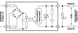
Scheme for connecting the relay to the load circuit Electrical circuit diagram