The cunning and useful Atmel U211B chip will help us. Anyone who has an old engine sitting idle should go to the soldering iron. The following describes the practical implementation of the controller for starting it and adjusting the speed.
↑ Intro
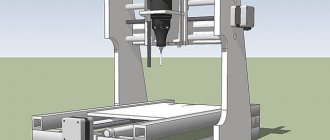
It all started with a successful purchase: a small lathe.
Accurate, not damaged by rough handling, but there was a problem with the drive part. The previous owner apparently used an ordinary asynchronous motor, and regulated the speed by throwing a belt from one pair of pulleys to another. This is better than nothing, but still far from the most correct approach. We wanted to be able to adjust the speed within a wide range, which allows us to process workpieces of different diameters with the same ease.
The simplest regulator circuit
Refer to this diagram. To reduce the speed of the electric motor, you need a PWM modulator, also known as a triac. This is a microcircuit that modulates a PWM signal, which allows you to set its own frequency.
In this circuit, the role of a modulator is played by the U2008B chip. This inexpensive board is designed specifically for adjusting the speed of an asynchronous motor.
According to the Electrical Systems company website, you will also need a diode and a resistor to reduce the voltage. In the diagram they are shown with signs D1 and R1. Also, to filter the incoming electricity, a power capacitor, designated C1, is needed.
P1, R5 and R3 are voltage dividers designed to regulate voltage. The second resistor is needed to synchronize the internal motor blocks with the triac.
To keep the frequency regulator safe, it is recommended to install a regular 1.5 amp fuse.
If you want to make a professional board, grab this printable circuit:
All that remains is to transfer it to foil PCB and etch it. You can view the instructions here. The asking price for such a regulator is 200 rubles.
↑ My washing machine engine
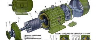
Modern washing machines use motors that are perfect for this task. There are many models, but they all have some design features in common: they are brushed, with sequential excitation and have a speed sensor
! And also a pulley for the poly V-belt. So different and so the same... I came across this one, Italian, 350-14000 rpm:
ATTENTION! It is impossible to turn on motors with sequential excitation without a load and without a speed controller.
They theoretically have no such thing as idle speed.
The engine can spin up to monstrous speeds, that is, it can go into overdrive. If you want to check the performance of the engine, you can poke it for a second
. You can't leave it for too long!
Speed controller circuit for an electric motor
Of course, a 220V electric motor speed controller can be bought in a store, but:
- It is difficult to find boards for mains voltage in stores (the main part of the market is regulators up to 35 volts).
- Those sold for network engines are of mediocre quality. They do not support power and speed, so they are not suitable for machine tools (for example, lathes) in principle.
- Industrial controllers that maintain speed and power are very expensive and difficult to purchase.
Why not collect it then? All parts are sold at any radio store, and you won’t need to program or flash anything, although you will need a microcircuit.
↑ RPM sensor
On the reverse side we see the speed sensor.
Inside it looks something like this: It's just a small alternator.
The task is to count the number of pulses; if for some reason they follow too slowly, the controller “applies gas” until the speed returns to normal. Thanks to feedback, you can turn the engine even very slowly without losing torque. Do not forget, in order to give a significant load to the engine, you need to use an additional cooling fan, since the performance of the original impeller at low speeds is not enough.
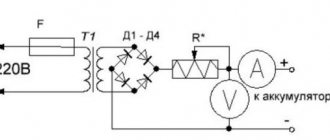
Washing machine motor speed controller
Connecting the electric motor speed controller for a washing machine, first of all, it is recommended to disassemble and check the presence of a triac - a power element. It should be on the radiator. If it is not there, it should be additionally installed so that the regulator does not overheat. The radiator is lubricated with thermal paste for better thermal separation.
After this, the regulator is assembled and connected to the engine according to the diagram shown on the housing. This makes it possible to regulate and stabilize the speed, increasing the voltage amplitude. At the same time, the power of the device increases.
↑ Electronics. Why Atmel U211B?
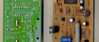
A similar controller based on the TDA1085 is quite popular. The same circuit and board are reprinted all over the Internet, and it works for everyone except me. Unfortunately, I was never able to achieve anything from him. It looks like either the microcircuits were slightly fake, or the hands were just crooked. Remains of an unsuccessful layout:
U211B chip from Atmel
promised exactly the same functionality, but the circuit is a little simpler, the board is a little simpler, the setup is much simpler. See for yourself:
Fragment excluded. The full version is available to patrons and full members of the community.
There are versions of the circuit on U211B for working with optical sensors and Hall sensors. Examples of various applications can be found in the documentation for the chip (see archives for the article). For those who want to understand the topic in more depth, I once again refer you to the datasheet.
Ways to connect the speed controller
How to connect the speed controller? Let's consider Motor Speed Controller 400W for 3 reasons:
- This is the most popular speed controller.
- There are problems connecting it due to the markup in Chinese.
- The connection is almost no different from having assembled it yourself.
To begin with, it is worth studying the connection diagram printed on the side of the regulator or the device passport.
Now you need to use the pinout on the back panel. You will need to select the necessary conclusions. The CCW and COM pins are always shorted and should not be touched. To connect you will need to use the 3 bottom contacts. AC ~ AC is zero and phase (the wires are installed arbitrarily, but the current is alternating). The ground wire, if present, is inserted into the FG.
In general, the preparation is complete. All that remains is to insert the plug from the regulator to the motor terminal block.
It is recommended to place a capacitor in the gap in the phase wire.
It will help smooth out incoming tension. It also wouldn't hurt to install a ferrite filter. It will help smooth out interference during work.
↑ Setting up the speed controller and protection
To be honest, it is impossible to say for sure that this circuit will be ideal for your engine.
The fact is that the engines, despite all their similarities, are different and in order for everything to work correctly, you need to carefully read the datasheet and calculate each denomination. I confess, I did not do this. I'm already tired of all this fuss with the TDA1085, I just wanted to turn it on and finally hear the motor working! I made changes only in the part that is responsible for the input from the sensor and selected R3, R16, R17 and C11. It worked, oddly enough. Resistor R4 (0.47 Ohm 2 W) plays the role of a current shunt; the protection uses it to detect overload. It is selected depending on the engine power using the formula from the datasheet. My resistor is made up of two 5-watt “white bricks” of 0.22 Ohm each in series. Whatever was on hand at the time of assembly.
Trimmer R8 sets the sensitivity of the protection. I had to unscrew it almost all the way to the right, it seems that the R4 rating is still too big. In the middle position of the R8, the engine did not start at all.
By selecting R16, R17, the minimum and maximum speeds are set.
Trimmer R10 sets the minimum voltage on the motor. Even if you short-circuit R16 and set the speed to zero using the R15 variable, the motor will continue to spin from this voltage, but without stabilizing the speed.
If the motor shaft is stopped, the controller will understand this and will try to restart it with full power pulses. First short, then longer.
C11 is the master element of the frequency-to-voltage converter. Depending on how many pulses the sensor gives per revolution, it can differ within very wide limits. In our case, 22 nF works fine.
Controller Specifications
The circuit will have the following characteristics:
- Operating voltage - from 110 to 230 volts.
- Adjustment possibilities – 9 – 99%. In general, this indicator depends on the chosen dimer.
- Load – up to 2.5 kilowatts.
- Operating power – 300 watts without radiator. If you install good cooling, you can increase it by 20-25%.
This speed controller circuit for a 220V brushed motor is quite quiet and has a smooth start. Assembling it is quite simple.
↑ Electric motor in operation, photos and videos
With these ratings everything spins perfectly, the engine has been tested in real operation.
In the video there is an attempt to put a load on the shaft by hand. Don’t repeat such hooliganism, don’t violate safety regulations!