One of the most important decisions engineers make when designing any type of motion control process is the choice of motor (in our case, an electric motor). The correct choice of motor, both in type and size, is a prerequisite for the efficient operation of the final machine. In addition, “keeping within budget” is also not the least important task.
One of the first questions to answer when making a decision is: what type of electric motor is best? Does the application require a high performance servo motor? Would a low cost stepper motor be better? Or maybe it’s worth considering a third, middle option?
The answers start with the needs of the specific application. There are many factors to consider before determining the type of electrical machine that is ideal for any particular application.
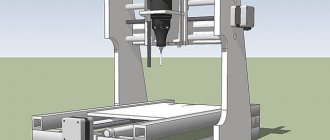
CNC Router Size
The size of CNC routers plays a vital role when choosing a motor.
If you want to set up a CNC router with a small footprint and small work area, a stepper motor may be better than a servo.
Typically, stepper motors are used to drive linear motion components such as the belt drive, lead screw, and ball screw of CNC routers with a maximum cutting area of 4 x 4 feet.
Some entry-level industrial CNC routers with 4' x 8' and 5' x 10' cutting areas also use stepper motors, which helps keep the cost down.
In large CNC routers, the gantry size is large and prone to bending, and a heavier structure is used to prevent bending.
In such cases, a servo motor is a more suitable choice.
Servo motors
Another factor is the size of the engine itself. Due to their complex design, servo motors are larger and heavier than stepper motors.
This means that for small CNC applications, steppers are the best choice.
Engine control
Stepper motors move a set number of steps with each pulse, and the controller has no way of knowing whether the motor has moved.
Whereas, a servo motor has a closed loop control, which means the motor sends information about its position and direction back to the controller.
This way the controller can check if any error has occurred. This can be crucial when working with expensive workpieces.
For example, let's say you're making a 2-inch cut on an expensive piece of work and something jams your linear actuators or gantry.
If you are using stepper motors, the motor will skip a few steps and continue cutting, and because it skipped steps, it will stop and not cut until 2 inches.
You'll have to throw away the workpiece (or repurpose it) and start over.
Whereas if you use servos, the controller knows how far the axis has actually moved and will continue to move until it completes the entire cut.
Well, this also means that a servo motor controller is more complex and expensive than a stepper motor controller.
Another option to achieve good results at low cost is to use stepper motors with feedback.
These motors are not as expensive as servo motors and have all the characteristics of a stepper motor with the added benefit of preventing errors.
For example, ToAUTO has a NEMA 23 stepper motor with feedback. It has position sensors that provide feedback for position correction.
So if you want to make precise cuts on workpieces for applications where any mistake could have catastrophic consequences, servo motors are ideal.
However, programming a servo is more difficult than programming a stepper motor, making stepper motors a better choice for beginners.
Stepper motor with controller
Solving the problem of lack of feedback
Over the past few decades, several different approaches have been proposed to solve traditional open-loop stepper motor problems. Connecting the motor to the sensor at power up or even several times during application was one way. Although simple, it slows things down and doesn't solve problems that arise during normal workflows.
Adding feedback to determine if the engine is stalling or stalled is another approach. Engineers at motion control companies have created "stall detection" and "attitude maintenance" functions. There have even been a few approaches that have gone even further, treating stepper motors the same as servos, or at least simulating them using fancy algorithms.
In the broad spectrum of electrical machines—between servos and open-loop stepper motors—lies a somewhat new technology known as the closed-loop stepper motor. This is the best and most cost-effective way to solve the problem of applications that require positioning accuracy and low speeds. By using high-resolution feedback devices to “close the loop,” engineers can enjoy the “best of both worlds.”
Closed-loop stepper motors absorb all the advantages of stepper motors: ease of use, simplicity, and the ability to operate stably at low speeds with precise stopping. Additionally, they still offer servo motor feedback capabilities. Luckily, this doesn't have to come with the servo's biggest drawback: the hefty price tag.
The key has always been the principle of operating stepper motors without feedback. They usually have two coils, sometimes five, with magnetic balancing occurring between them. Movement upsets this balance, causing the motor shaft to lag electrically, but the operator has no way of knowing how much it is lagging. The stopping point is repeated for open loop steppers, but not for all loads. Mounting an encoder on the stepper and closing the feedback loop provides some dynamic control. This allows operators to accurately position the implement under varying loads.
These benefits of using closed-loop stepper motors for certain applications have dramatically increased the popularity of these motors in the electrical drive engineering community. In particular, two of the most popular industries—semiconductor and medical device manufacturing—are seeing a clear increase in the use of closed-loop stepper motors. Engineers in these industries must know exactly where the load-bearing motor shaft is located, whether they are driving a belt or a ball screw. The feedback in these electric drives allows them to know exactly where the shaft is. They can also provide better performance than servos at lower speeds.
Generally, any application that requires guaranteed performance at a lower cost than a servo motor and the ability to operate at relatively low speeds is a good candidate for closed-loop stepper motors.
Remember that operators must ensure that the drive or operating controls support closed-loop stepper motors. "Historically", you could get a stepper with an encoder on the back, but the control system did not support encoders. You will need to calibrate the feedback and ensure that the motor controller is receiving feedback within an acceptable delay. This is not required in new closed-loop stepper drives. Closed-loop stepper drives can dynamically and automatically control position and speed without the involvement of controllers.
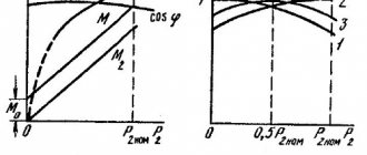
Speed and torque
Stepper motors operate efficiently at 1200 rpm or lower and can produce high torque at low speeds.
You can find stepper motors with holding torque typically ranging from 30 to 1500 oz./in.
But this torque decreases as engine speed increases, sometimes by up to 80% at very high speeds.
Servo motors operate at over 2000 RPM and are available with much higher torque ratings than stepper motors, making them faster than stepper motors.
The great thing about servo motors is that they are capable of delivering constant torque throughout the entire speed range.
It is clear that servos have better torque characteristics compared to stepper motors, so if you want to use really heavy spindles, you may need servos.
Additionally, if you are using heavy gantry units along with a heavy spindle, you should consider using servos to increase speed.
In addition, servos perform better under dynamic loads.
This means that the servos operate consistently across different materials and cutting settings as they are subjected to different loads.
But that doesn't mean stepper motors are always a bad choice for large CNCs.
The NEMA 34 stepper motor can drive a 7 HP spindle. on a CNC router from aluminum and steel and still achieve high speeds of approximately 1000 inches per minute.
Torque. Stepper motors and servo motors
Another significant difference between the two is the time spent cutting. Engines cannot reach full speed instantly, they take time to accelerate to full speed and stop.
When it comes to acceleration and braking, servos are faster by a few milliseconds compared to stepper motors.
A few milliseconds won't matter if you're producing parts with fast cycle times and minimal changes in cutting direction.
But when you make parts that require the spindle to change direction frequently, the motors must stop and then accelerate in the new direction.
In such cases, those milliseconds add up and there is a significant difference in project completion time between servos and stepper motors.
The bottom line is that if you work in a manufacturing environment where production speed is of the essence, you should use servos.
Asynchronous motors
The most common electrical machines. They are mainly used as electric motors and are the main converters of electrical energy into mechanical energy. An induction motor has a stator (fixed part) and a rotor (moving part), separated by an air gap, the rotor is mounted on bearings. The active parts are the windings; all other parts are structural, providing the necessary strength, rigidity, cooling, rotation, etc. Based on the rotor design, asynchronous machines are divided into two main types: with a squirrel-cage rotor and with a wound rotor. Both types have the same stator design and differ only in the design of the rotor winding. The rotor magnetic circuit is made similarly to the stator magnetic circuit - made of electrical steel and laminated. A wound rotor is used when it is necessary to create a large starting torque. Current is supplied to the rotor and as a result, a magnetic flux necessary to create torque appears.
Voltage is applied to the stator winding, under the influence of which current flows through these windings and creates a rotating magnetic field. The magnetic field acts on the rotor rods and, according to the law of magnetic induction, an electric current arises because the magnetic flux passing through the closed circuit of the rotor changes. The currents in the rotor bars create their own magnetic field of the bars, which interact with the rotating magnetic field of the stator. As a result, a force acts on each rod, which, when added in a circle, creates a rotating electromagnetic torque of the rotor due to the fact that the induced current arising in the closed circuit of the rotor has such a direction that the magnetic field it creates counteracts the change in the magnetic flux that caused given current. Consequently, rotation occurs. The frequency of rotation of the rotor cannot reach the frequency of rotation of the magnetic field, since in this case the angular speed of rotation of the magnetic field relative to the rotor winding will become equal to zero, the magnetic field will no longer induce E.M.F. in the rotor winding. and, in turn, create torque.
Figure 3 — Sectional view of an asynchronous machine with a squirrel-cage rotor
The figure shows a cross-sectional view of an asynchronous machine with a squirrel-cage rotor:
1 - bed,
2 - stator core,
3 - stator winding,
4 - rotor core with short-circuited winding,
5 - shaft.
Torque Hold
Holding torque determines the ability of the motor shaft to remain in place when the coils are energized.
A stepper motor will not rotate without an input signal as long as the motor shaft torque is less than the motor holding torque.
Whereas in a servo motor there is almost no holding torque. So how does a servo motor hold the load in place?
The feedback mechanism in the servo motor detects any change in the shaft position and instantly corrects the shaft position. It mostly oscillates in the held position, but the oscillation is minor.
But when servos are not adjusted correctly, they produce vibration and noise while holding the load in a stationary position.
Holding torque is a major factor when you need to hold a load in a vertical direction, such as in the case of a Z-axis spindle.
This is especially important when you are using ball screws for linear motion.
Ball screws have low internal friction and can be reverse driven.
This means that if you use a ballscrew on the Z axis and lift the spindle up, the weight of the spindle can push the ballscrew down.
To prevent this, the motor connected to the linear motion component must have sufficient holding torque to prevent the linear motion components load from moving backwards.
Using a stepper motor with sufficient holding torque is a simple and easy way to achieve this.
Servos can do just as good a job, but you'll need to carefully tune the controller to prevent unnecessary vibration and noise that could damage other components in your build.
Stepper motor with ball screw
Input Power and Efficiency
Stepper motors operate on DC current and typically run at full power regardless of load. Stepper motors have an efficiency of about 70%.
On the other hand, you can find servos that operate from an AC or DC source, and they draw power proportional to the load they carry, so servos can be 80-90% efficient.
Energy consumption is a factor to consider when you're working in a production environment, and the extra money you spend on servos can save you money on your energy bills.
However, if your production volumes are small and loads are smaller, there is no real cost benefit to investing in a servo drive, making stepper motors a better choice.
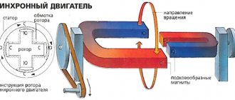
Synchronous motors
A synchronous motor has no fundamental design differences from asynchronous motors. A three-phase winding is placed on the stator of a synchronous motor, when connected to a three-phase alternating current network, a rotating magnetic field will be created, the number of revolutions per minute of which is n = 60f/p, where f is the frequency of the drive supply voltage. An excitation winding is placed on the motor rotor, which is connected to the DC source network. Or the rotor is made of a permanent magnet. The excitation current creates the magnetic flux of the poles or in the case of a permanent magnet, the magnetic flux has already been created. The rotating magnetic field produced by the stator winding currents drags the rotor poles along with it. In this case, the rotor can only rotate at synchronous speed, i.e. at a speed equal to the rotation speed of the stator field. Thus, the speed of a synchronous motor is strictly constant if the frequency of the supply network current remains unchanged.
The advantage of synchronous motors is that they are less sensitive to changes in supply voltage than asynchronous motors. For synchronous motors, the torque is proportional to the network voltage to the first power, while for asynchronous motors it is proportional to the square of the voltage. The torque of a synchronous motor is created as a result of the interaction of the magnetic field of the stator with the magnetic field of the poles. Only the magnetic flux of the stator field depends on the supply voltage.
Accuracy and repeatability
The resolution of CNC motors is a factor that affects the accuracy and repeatability of CNC routers.
Typically, the resolution of stepper motors depends on the number of steps.
A typical stepper motor has 200 steps, which means it turns 1.8 degrees for every pulse it receives.
If you use microstepping you can improve this resolution. For example, if you use 1/8 microstepping, the resolution will become 0.225 degrees on a 200-step motor.
Additionally, stepper motors are often preferred due to their simple design and open-loop system that require little to no tuning. Hence, they provide good accuracy without much adjustment.
On the other hand, servos use an encoder to determine the position of the motor shaft, and the resolution of the motor depends on the encoder and the controller's ability to accurately regulate voltage and current.
For example, if the servo motor has a resolution of 1000 pulses/rev, this indicates that the controller will be able to detect every 0.36 degrees of rotation of the motor shaft.
In theory, servos have infinite resolution, but you need to set them up correctly and keep the encoder and controller in good condition to achieve very high precision.
For hobbyist applications where you don't need high precision and accuracy, steppers are a reasonable choice.
However, stepper motors can skip steps and cause erroneous cuts when they get hot due to continuous operation.
Servo motors have better positioning accuracy than stepper motors.
This is because servo motors have a closed control loop, which allows them to adjust their movements.
You can also get good repeatability from servos if they are rotated correctly. Their repeatability also depends on the quality of the encoder used.
Rotary encoder for determining shaft position
Noise
Noise can be a problem when working with CNC.
Stepper motors can be a little noisy compared to servo motors.
To overcome this, you can use stepper motor drivers that support microstepping, which helps reduce noise.
You can find stepper drivers that can control microstepping down to 1/128 to greatly reduce noise and keep the shaft moving smoothly at low speeds.
In addition, microstepping eliminates the influence of resonant frequency, which causes vibration in stepper motors.
However, microstepping can produce less torque, which can be about 70% of the torque produced by full-stepping control.
You can use servo motors to eliminate motor noise and vibration, but you will still have to worry about milling machine/spindle noise.
Typically, the router/spindle noise outweighs everything else, making the motor noise negligible.
Service life and maintenance
Stepper motors have fewer components, and the bearing is the only wear part that can be replaced.
Servo motors use encoders and gearboxes as core components, making them mechanically complex.
Hence, stepper motors require less maintenance compared to servo motors.
However, stepper motors are more susceptible to damage due to mechanical errors such as overload and jamming than servo motors.
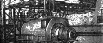
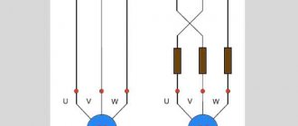
Servo drives
The servo drive consists of a servo motor and an electronic control unit (servo amplifier or servo converter). The most widely used servo motors are synchronous three-phase electric motors, in which powerful permanent magnets are installed to improve dynamic characteristics. An encoder is also a mandatory component of the servo drive. As a rule, it outperforms conventional encoders supplied separately. Its resolution can reach hundreds of thousands of pulses per revolution, due to which ultra-precise positioning is achieved. For example, the resolution of the built-in encoders of Delta ASD-A2 servo drives is 1,280,000 pulses/rev.
The servo amplifier receives two control signals - a speed (or angle of rotation) command signal and a feedback signal from the encoder. As a result, the servo drive ensures the movement of any mechanical load with great accuracy not only in terms of rotation speed, but also in the angle of rotation, which can be maintained to fractions of a degree.
Price
Cost is often the main reason for choosing stepper motors over servos.
A typical servo drive is at least three times more expensive than a stepper motor of the same size and power.
This is due to the complexity of its design.
Stepper motors use an open-loop system and have a simple design that eliminates complexity and added cost.
Additionally, servo motor controllers use complex circuitry to achieve high performance.
Stepper motor drivers are inexpensive compared to servos due to their simple design and availability.
Overall, the additional components and complex system make the servo motor system expensive.
Servo motor with driver
However, in an industrial production environment, the additional cost is justified by the higher efficiency of the servo motor system.
In addition, servo drives produce parts that have less waste and reduce wastage of raw materials.
Why are servo motors more expensive than stepper motors?
Servo motors use rare earth magnets, which are more expensive than the regular magnets used in stepper motors. Servo motors also have an encoder or resolver and a gearbox. Consequently, the overall layout makes servo motors mechanically more complex and more expensive than stepper motors.
Can I replace my servo motor encoder myself?
It is very difficult to replace the encoder in a servomotor yourself. This requires finding the offset between the encoder and the rotor position and is best done by trained service personnel.
Can I add an external encoder to my stepper motors?
You can add external encoders to your stepper motors. The encoder allows you to monitor the position and speed of the motor shaft. Adding an encoder to a stepper motor has a significant impact on the motor's performance.
Hybrid engines
Figure 5 - Design of hybrid motors
They are more expensive than permanent magnet motors, but they provide a smaller step size, higher torque and higher speed. Typical steps per revolution for hybrid engines range from 100 to 400 (step angle 3.6...0.9°). The rotor of a hybrid engine has teeth located in the axial direction. The rotor is divided into two parts, between which there is a cylindrical permanent magnet. Thus, the teeth of the upper half of the rotor are the north poles, and the teeth of the lower half are the south poles. In addition, the upper and lower halves of the rotor are rotated relative to each other by half the pitch angle of the teeth. The number of pairs of rotor poles is equal to the number of teeth on one of its halves. The toothed rotor pole pieces, like the stator, are assembled from separate plates to reduce eddy current losses. The stator of a hybrid motor also has teeth, providing a large number of equivalent poles as opposed to the main poles on which the windings are located. Typically 4 main poles are used for 3.6° motors and 8 main poles for 1.8...0.9° motors. Rotor teeth provide less resistance to the magnetic circuit at certain rotor positions, which improves static and dynamic torque. This is ensured by the appropriate arrangement of the teeth, when part of the rotor teeth is strictly opposite the stator teeth, and part is between them. The relationship between the number of rotor poles, the number of equivalent stator poles and the number of phases determines the pitch angle S of the motor:
S = 360 / ( Nph × Ph ) = 360 / NS = 360 / ( Nph times Ph ) = 360 / N
where Nph is the number of equivalent poles per phase equal to the number of rotor poles, Ph is the number of phases, N is the total number of poles for all phases together.