What are circuit breakers for and how do they work?
Modern AVs have two degrees of protection: thermal and electromagnetic. This allows you to protect the line from damage as a result of prolonged excess of the flowing current of the rated value, as well as a short circuit.
The main element of the thermal release is a plate made of two metals, which is called bimetallic. If it is exposed to a current of increased power for a sufficiently long time, it becomes flexible and, acting on the disconnecting element, causes the circuit breaker to operate.
The presence of an electromagnetic release determines the breaking capacity of the circuit breaker when the circuit is exposed to short-circuit overcurrents, which it cannot withstand.
An electromagnetic type release is a solenoid with a core, which, when a high power current passes through it, instantly moves towards the disconnecting element, turning off the protective device and de-energizing the network.
This makes it possible to protect the wire and devices from an electron flow, the value of which is much higher than that calculated for a cable of a particular cross-section.
Calculation of an automatic machine for an electric motor
Power calculation
Until recently, the following scheme was used to protect electric motors: a thermal regulator was installed inside the starter, connected in series with the contactor. This mechanism worked like this. When a large current passed through the relay for a long time, the bimetallic plate installed in it was heated, which, bending, interrupted the contactor circuit. If the excess of the set load was short-term (as happens when starting the engine), the plate did not have time to heat up and trigger the machine.
Internal structure of the motor protection circuit breaker in the video:
The main disadvantage of this scheme was that it did not save the unit from voltage surges, as well as phase imbalance. Nowadays, the protection of electric power plants is provided by more accurate and modern devices, which we will talk about a little later. Now let’s move on to the question of how to calculate the machine that needs to be installed in the electric motor circuit.
To select a protective circuit breaker for an electrical installation, you need to know its time-current characteristics, as well as its category. The time-current characteristic does not depend on the rated current for which the AV is designed.
To prevent the circuit breaker from tripping every time the motor is started, the value of the starting current should not be greater than that which causes the device to immediately operate (cut-off). The ratio of the starting current and the nominal value is specified in the equipment passport, the maximum allowable is 7/1.
When calculating the machine practically, you should use the reliability coefficient, denoted by the symbol Kn. If the rated current of the device does not exceed 100A, then the value of Kn is 1.4; for larger values it is 1.25. Based on this, the value of the cut-off current is determined by the formula Iots ≥ Kn x Istart. We select the circuit breaker in accordance with the calculated parameters.
Another value that must be taken into account when selecting when the machine is mounted in an electrical panel or a special cabinet is the temperature coefficient (CT). This value is 0.85, and the rated current of the protective device should be multiplied by it when selecting (In/Kt).
What is the machine used for?
A machine is installed in the power supply circuit to prevent overheating of the wiring. Any wiring is designed to carry a certain current. If the current passed exceeds this value, the conductor begins to heat up too much. If this situation persists for a sufficient period of time, the wiring begins to melt, resulting in a short circuit. A circuit breaker is installed to prevent this situation.
A packager or circuit breaker is necessary to prevent overheating of conductors and shutdown in the event of a short circuit
The second task of the circuit breaker is to turn off the power when a short circuit current (SC) occurs. When a short circuit occurs, the currents in the circuit increase many times over and can reach thousands of amperes. To prevent them from destroying the wiring and damaging the equipment included in the line, the circuit breaker must turn off the power as quickly as possible - as soon as the current exceeds a certain limit.
In order for the protective circuit breaker to properly perform its functions, it is necessary to correctly select the machine according to all parameters. There are not many of them - only three, but you need to deal with each one.
Functions of three-phase machines
Before choosing an automatic switch, you should understand its functionality. Users are often mistaken into thinking that the device protects household appliances. The machine does not respond to its electrical indicators, only triggering in the event of a short circuit or overload. The three-phase functions include:
- simultaneous maintenance of several single-phase circuit zones;
- preventing the formation of overcurrents on the line;
- joint work with AC rectifiers;
- protection of high-power equipment;
- increased power due to the installation of a special converter;
- fast response in short circuit mode on a line with a large number of consumers;
- the ability to turn off manually using a switch or switch;
- Compatible with optional safety terminals.
Without a automatic device, the risk of cable fire increases.
Why is a short circuit dangerous?
This situation can arise during repairs if an electrician accidentally shorts the neutral and phase wires together, or due to the destruction of insulation in an adapter box or some electrical appliance.
In this case, the current flowing in the wires can grow to a very large value, limited only by the resistance of the wires and the capabilities of the line. In this case, the current-carrying conductors heat up to the temperature at which the insulation ignites, which can lead to a fire, so it is necessary to immediately turn off the power to the line.
Diagram of a 3-pole circuit breaker
Each 3-pole circuit breaker is three single-pole circuit breakers that operate simultaneously. One phase is connected to each terminal of a 3-pole circuit breaker.
Diagram of a 3-pole circuit breaker
As can be seen from the diagram, each circuit has separate electromagnetic and thermal releases, and the body of the 3-pole circuit breaker has separate arc extinguishers.
A 3-pole circuit breaker can also be used in a single-phase power supply. In this case, the phase and neutral wires are connected to two terminals of the switch, and the third terminal remains empty (signal).
Why turn off the network when overloaded?
No less dangerous is line overload. When more than rated current flows through the wires, they heat up. This leads to destruction of the cable insulating sheath and subsequent short circuit.
The process of heating the wires takes some time, so to protect the line from overload, protection is used that turns off the power to electrical appliances some time after the problem occurs.
| Information! An increased current when starting an electric motor is normal and lasts less than the response delay of the machine. |
The cause of overload may be the simultaneous switching on of high-power electrical appliances, a malfunction of electrical equipment, or the start of an electric motor, for example, in a vacuum cleaner or air conditioner.
If almost any circuit breaker is tripped by a short circuit, then an incorrectly selected device will turn off the power at the rated current of the line or will not be able to protect the wiring from overheating, so before installation it is necessary to calculate the power of the circuit breaker.
Rules for choosing denomination
The geometry of intra-apartment and house electrical networks is individual, so there are no standard solutions for installing switches of a certain rating. The general rules for calculating the permissible parameters of machines are quite complex and depend on many factors. It is necessary to take them all into account, otherwise an emergency situation may be created.
The principle of indoor wiring
Internal electrical networks have a branched structure in the form of a “tree” - a graph without cycles. Compliance with this principle of construction is called selectivity of machines, according to which all types of electrical circuits are equipped with protective devices.
This improves the stability of the system in the event of an emergency and simplifies the work to eliminate it. It is also much easier to distribute the load, connect energy-intensive devices and change the wiring configuration.
At the base of the graph there is an input machine, and immediately after the branching, group switches are placed for each individual electrical circuit. This is a standard scheme proven over the years
The functions of the input circuit breaker include monitoring the general overload - preventing the current from exceeding the permitted value for the object. If this happens, there is a risk of damage to the external wiring. In addition, it is likely that protective devices outside the apartment, which are already part of the common property or belong to the local power grid, will be triggered.
The functions of group machines include current control on individual lines. They protect the cable in a dedicated area and the group of electricity consumers connected to it from overload. If such a device does not operate during a short circuit, then it is insured by an input circuit breaker.
Even for apartments with a small number of electrical consumers, it is advisable to install a separate line for lighting. When you turn off the circuit breaker of another circuit, the light will not go out, which will allow you to eliminate the problem in more comfortable conditions. In almost every panel, the nominal value of the input machine is less than the amount on the group ones.
Total power of electrical appliances
The maximum load on the circuit occurs when all electrical appliances are turned on at the same time. Therefore, usually, the total power is calculated by simple addition. However, in some cases this figure will be less.
For some lines, the simultaneous operation of all electrical appliances connected to it is unlikely, and sometimes impossible. Homes sometimes specifically place restrictions on the operation of powerful devices. To do this, you need to remember not to turn them on at the same time or use a limited number of sockets.
The probability of simultaneous operation of all office equipment, lighting and auxiliary equipment (kettles, refrigerators, fans, heaters, etc.) is very low, therefore, when calculating the maximum power, a correction factor is used
When electrifying office buildings, the empirical simultaneity coefficient is often used for calculations, the value of which is taken in the range from 0.6 to 0.8. The maximum load is calculated by multiplying the sum of the powers of all electrical appliances by a factor.
There is one subtlety in the calculations - it is necessary to take into account the difference between the rated (total) power and consumed (active), which are related by the coefficient (cos (f)).
This means that for the device to operate, a power current equal to the consumed divided by this coefficient is required:
Ip = I/cos(f)
Where:
- Ip is the rated current used in load calculations;
- I is the current consumed by the device;
- cos(f) <= 1.
Usually the rated current is indicated immediately or through the indication of the cos (f) value in the technical data sheet of the electrical device.
For example, the coefficient value for fluorescent light sources is 0.9; for LED lamps – about 0.6; for ordinary incandescent lamps - 1. If the documentation is lost, but the power consumption of household devices is known, then for guarantee take cos (f) = 0.75.
The recommended power factor values shown in the table can be used when calculating electrical loads when rated current data is not available.
How to select a circuit breaker based on load power is described in the following article, the contents of which we recommend that you familiarize yourself with.
Selection of core cross-section
Before laying a power cable from the distribution panel to a group of consumers, it is necessary to calculate the power of electrical appliances when they operate simultaneously. The cross-section of any branch is selected according to calculation tables depending on the type of wiring metal: copper or aluminum.
Wire manufacturers provide similar reference materials to their products. If they are missing, then they are guided by the data from the reference book “Rules for the Construction of Electrical Equipment” or calculate the cable cross-section.
However, consumers often play it safe and choose not the minimum acceptable cross-section, but one step larger. So, for example, when purchasing a copper cable for a 5 kW line, choose a core cross-section of 6 mm2, when according to the table a value of 4 mm2 is sufficient.
The reference table presented in the PUE allows you to select the required cross-section from the standard range for various operating conditions of the copper cable
This is justified for the following reasons:
- Longer service life of a thick cable, which is rarely subjected to the maximum permissible load for its cross-section. Re-wiring is not an easy and expensive job, especially if the room has been renovated.
- The bandwidth reserve allows you to seamlessly connect new electrical appliances to the network branch. So, you can add an additional freezer to the kitchen or move the washing machine there from the bathroom.
- The start of operation of devices containing electric motors produces strong starting currents. In this case, a voltage drop is observed, which is expressed not only in the blinking of the lighting lamps, but can also lead to breakdown of the electronic part of the computer, air conditioner or washing machine. The thicker the cable, the smaller the voltage surge will be.
Unfortunately, there are many cables on the market that are not made according to GOST, but according to the requirements of various specifications.
Often the cross-section of their cores does not meet the requirements or they are made of conductive material with greater resistance than required. Therefore, the actual maximum power at which permissible heating of the cable occurs is less than in the standard tables.
This photo shows the differences between cables made according to GOST (left) and according to TU (right). There is an obvious difference in the cross-section of the conductors and the tightness of the insulating material.
Calculation of the circuit breaker rating for cable protection
The machine installed in the panel must ensure that the line is disconnected when the current power goes beyond the range permitted for the electric cable. Therefore, it is necessary to calculate the maximum permissible rating for the switch.
According to the PUE, the permissible long-term load of copper cables laid in boxes or in the air (for example, over a suspended ceiling) is taken from the table above. These values are intended for emergency situations when there is a power overload.
Some problems begin when relating the rated power of the switch to the long-term permissible current, if this is done in accordance with the current GOST R 50571.4.43-2012.
A fragment of clause 433.1 of GOST R 50571.4.43-2012 is given. There is an inaccuracy in formula “2”, and for a correct understanding of the definition of the variable In, you need to take into account Appendix “1”
Firstly, deciphering the variable In as rated power is misleading, if you do not pay attention to Appendix “1” to this paragraph of GOST. Secondly, there is a typo in formula “2”: the coefficient of 1.45 was added incorrectly, and this fact is stated by many experts.
According to clause 8.6.2.1. GOST R 50345-2010 for household switches rated up to 63 A, the conditional time is 1 hour. The set tripping current is equal to the nominal value multiplied by a factor of 1.45.
Thus, according to both the first and modified second formulas, the rated current of the circuit breaker must be calculated using the following formula:
In <= IZ / 1.45
Where:
- In – rated current of the machine;
- IZ – long-term permissible cable current.
Let's calculate the ratings of switches for standard cable sections for a single-phase connection with two copper conductors (220 V). To do this, we divide the long-term permissible current (when laying through the air) by a tripping coefficient of 1.45.
Let's choose a machine so that its face value is less than this value:
- Section 1.5 mm2: 19 / 1.45 = 13.1. Rating: 13 A;
- Section 2.5 mm2: 27 / 1.45 = 18.6. Rating: 16 A;
- Section 4.0 mm2: 38 / 1.45 = 26.2. Rating: 25 A;
- Section 6.0 mm2: 50 / 1.45 = 34.5. Rating: 32 A;
- Section 10.0 mm2: 70 / 1.45 = 48.3. Rating: 40 A;
- Section 16.0 mm2: 90 / 1.45 = 62.1. Rating: 50 A;
- Section 25.0 mm2: 115 / 1.45 = 79.3. Denomination: 63 A.
13A circuit breakers are rarely on sale, so devices with a rated power of 10A are often used instead.
Cables based on aluminum cores are now rarely used when installing internal wiring. There is also a table for them that allows you to select a section based on load
In a similar way, for aluminum cables we calculate the ratings of the machines:
- Section 2.5 mm2: 21 / 1.45 = 14.5. Rating: 10 or 13 A;
- Section 4.0 mm2: 29 / 1.45 = 20.0. Rating: 16 or 20 A;
- Section 6.0 mm2: 38 / 1.45 = 26.2. Rating: 25 A;
- Section 10.0 mm2: 55 / 1.45 = 37.9. Rating: 32 A;
- Section 16.0 mm2: 70 / 1.45 = 48.3. Rating: 40 A;
- Section 25.0 mm2: 90 / 1.45 = 62.1. Rating: 50 A.
- Section 35.0 mm2: 105 / 1.45 = 72.4. Denomination: 63 A.
If the power cable manufacturer declares a different dependence of the permissible power on the cross-sectional area, then it is necessary to recalculate the value for the switches.
The formulas for the dependence of current on power for single-phase and three-phase networks are different. Many people who have devices designed for 380 Volts make a mistake at this stage
How to determine the technical parameters of a circuit breaker by marking is described in detail here. We recommend that you read the educational material.
What is the standard line of current circuit breakers?
According to the PUE, each device has an inscription that indicates the nominal value of electrical energy. To get this information, you just need to look at the device's body. It has a letter and a number on it. In total, three letters are usually used for marking - B, C and D. The numbers indicate the amount of charge. The letter shows the time characteristic or period for which the device operates.
Equipment marking
Devices with the first two letters are used for home use. In industry, protective devices D are needed. More powerful units, designated by the letters L, Z and K, are also used. Their rated values are higher than in household, apartment devices.
The standard line includes mini circuit breakers, air circuit breakers, enclosed circuit breakers, residual current circuit breakers and residual current circuit breakers.
Note! The marking also indicates the series, operating voltage, poles and breaking capacity.
Table of circuit breakers for single-phase 220 V network
| Rated current of the circuit breaker, A. | Power, kWt. | Current, 1 phase, 220V. | Cable core cross-section, mm2 |
| 16 | 0-2,8 | 0-15,0 | 1,5 |
| 25 | 2,9-4,5 | 15,5-24,1 | 2,5 |
| 32 | 4,6-5,8 | 24,6-31,0 | 4 |
| 40 | 5,9-7,3 | 31,6-39,0 | 6 |
| 50 | 7,4-9,1 | 39,6-48,7 | 10 |
| 63 | 9,2-11,4 | 49,2-61,0 | 16 |
| 80 | 11,5-14,6 | 61,5-78,1 | 25 |
| 100 | 14,7-18,0 | 78,6-96,3 | 35 |
| 125 | 18,1-22,5 | 96,8-120,3 | 50 |
| 160 | 22,6-28,5 | 120,9-152,4 | 70 |
| 200 | 28,6-35,1 | 152,9-187,7 | 95 |
| 250 | 36,1-45,1 | 193,0-241,2 | 120 |
| 315 | 46,1-55,1 | 246,5-294,7 | 185 |
Table of circuit breakers for three-phase 380 V network
| Rated current of the circuit breaker, A. | Power, kWt. | Current, 1 phase 220V. | Cross-section of cable cores, mm2. |
| 16 | 0-7,9 | 0-15 | 1,5 |
| 25 | 8,3-12,7 | 15,8-24,1 | 2,5 |
| 32 | 13,1-16,3 | 24,9-31,0 | 4 |
| 40 | 16,7-20,3 | 31,8-38,6 | 6 |
| 50 | 20,7-25,5 | 39,4-48,5 | 10 |
| 63 | 25,9-32,3 | 49,2-61,4 | 16 |
| 80 | 32,7-40,3 | 62,2-76,6 | 25 |
| 100 | 40,7-50,3 | 77,4-95,6 | 35 |
| 125 | 50,7-64,7 | 96,4-123,0 | 50 |
| 160 | 65,1-81,1 | 123,8-124,2 | 70 |
| 200 | 81,5-102,7 | 155,0-195,3 | 95 |
| 250 | 103,1-127,9 | 196,0-243,2 | 120 |
| 315 | 128,3-163,1 | 244,0-310,1 | 185 |
| 400 | 163,5-207,1 | 310,9-393,8 | 2x95* |
| 500 | 207,5-259,1 | 394,5-492,7 | 2x120* |
| 630 | 260,1-327,1 | 494,6-622,0 | 2x185* |
| 800 | 328,1-416,1 | 623,9-791,2 | 3x150* |
Automatic switches for household networks
Electricity supply organizations connect houses and apartments by carrying out work on connecting the cable to the switchboard. All installations of wiring in the premises are carried out by its owners or hired specialists.
To select a circuit breaker to protect each individual circuit, you need to know its rating, class and some other characteristics.
Basic parameters and classification
Household machines are installed at the entrance to a low-voltage electrical circuit and are designed to solve the following problems:
- manual or electronic activation or de-energization of an electrical circuit;
- circuit protection: current cut-off during minor long-term overload;
- Circuit protection: instantaneous shutdown of current in case of short circuit.
Each switch has a characteristic, expressed in amperes, which is called rated current (In) or “rating”.
The essence of this value is easier to understand using the coefficient of excess of the nominal value:
K=I/In,
where I is the actual current strength.
- K < 1.13: tripping will not occur within 1 hour;
- K > 1.45: shutdown will occur within 1 hour.
These parameters are fixed in clause 8.6.2. GOST R 50345-2010. To find out how long it will take for a shutdown to occur at K>1.45, you need to use a graph reflecting the time-current characteristic of a specific machine model.
If the current exceeds the rated value of the switch by 2 times for a long time, the opening will occur within a period of 8 seconds to 4 minutes. The response speed depends on the model settings and the ambient temperature
Also, each type of circuit breaker has a current range (Ia) at which the instantaneous tripping mechanism is triggered:
- class “B”: Ia = (3 * In ... 5 * In];
- class “C”: Ia = (5 * In … 10 * In];
- class “D”: Ia = (10 * In … 20 * In].
Type “B” devices are used mainly for lines that are of considerable length. In residential and office premises, class “C” machines are used, and devices marked “D” protect circuits where there is equipment with a high starting current coefficient.
The standard line of household machines includes devices with ratings of 6, 8, 10, 16, 20, 25, 32, 40, 50 and 63 A.
Structural design of releases
There are two types of releases in a modern circuit breaker: thermal and electromagnetic.
A bimetallic release has the shape of a plate created from two conductive metals with different thermal expansion. This design, when exceeding the nominal value for a long time, leads to heating of the part, its bending and the activation of the circuit breaking mechanism.
For some machines, you can use the adjusting screw to change the parameters of the current at which the shutdown occurs. In the past, this technique was often used to “fine-tune” a device, but this procedure requires in-depth specialized knowledge and several tests.
By rotating the adjusting screw (highlighted with a red rectangle) counterclockwise, you can achieve a longer response time for the thermal release
Now on the market you can find many models of standard ratings from different manufacturers, whose time-current characteristics are slightly different (but at the same time comply with regulatory requirements). Therefore, it is possible to select a machine with the required “factory” settings, which eliminates the risk of incorrect calibration.
The electromagnetic release prevents overheating of the line as a result of a short circuit. It reacts almost instantly, but the current value must be several times higher than the nominal value. Structurally, this part is a solenoid. The overcurrent generates a magnetic field that moves the core, breaking the circuit.
Compliance with selectivity principles
If there is a branched electrical circuit, it is possible to organize protection in such a way that in the event of a short circuit, only the branch on which the emergency situation occurs is disconnected. For this purpose, the principle of switch selectivity is used.
A visual diagram showing the principle of operation of a circuit breaker system with an implemented function of selectivity (selectivity) of operation when a short circuit occurs
To ensure selective shutdown, instantaneous cutoff circuit breakers are installed at the lower stages, breaking the circuit in 0.02 - 0.2 seconds. The switch located at a higher stage either has a response delay of 0.25 - 0.6 s or is made according to a special “selective” circuit in accordance with the DIN VDE 0641-21 standard.
To ensure selective operation of the machines, it is better to use machines from one manufacturer. For switches of a single model range, there are selectivity tables that indicate possible combinations.
The simplest installation rules
The section of the circuit that needs to be protected by a switch can be single- or three-phase, have a neutral, as well as a PE (“ground”) wire. Therefore, the machines have from 1 to 4 poles, to which the conductor is connected. When conditions for tripping are created, all contacts are disconnected simultaneously.
The machines in the panel are mounted on a specially designated DIN rail. It provides compact and safe connection, as well as convenient access to the switch
The machines are installed as follows:
- single-pole per phase;
- bipolar for phase and neutral;
- three-pole for 3 phases;
- four-pole for 3 phases and neutral.
However, it is prohibited to do the following:
- install single-pole circuit breakers to neutral;
- insert PE wire into the machine;
- install three single-pole ones instead of one three-pole circuit breaker, if at least one three-phase consumer is connected to the circuit.
All these requirements are specified in the PUE and must be followed.
In every house or room to which electricity is supplied, an introductory machine is installed. Its nominal value is determined by the supplier and this value is specified in the electricity connection agreement. The purpose of such a switch is to protect the area from the transformer to the consumer.
After the input circuit breaker, a meter (single- or three-phase) and a residual current device are connected to the line, the functions of which differ from the operation of an automatic and differential switch.
If the room is wired into several circuits, then each of them is protected by a separate circuit breaker, the power of which is indicated in the marking. Their ratings and classes are determined by the owner of the premises, taking into account the existing wiring or power of connected devices.
The electricity meter and circuit breakers are installed in a distribution board that meets all safety requirements and can easily be integrated into the interior of the room
When choosing a location for the distribution board, it must be remembered that the properties of the thermal release are affected by air temperature. Therefore, it is advisable to place the rail with machines inside the room itself.
Methods for selecting a difavtomat
For example, consider a kitchen where a large amount of equipment is connected. First, you need to set the total power rating for a room with a refrigerator (500 W), microwave (1000 W), kettle (1500 W) and hood (100 W). The total power indicator is 3.1 kW. Based on it, various methods are used to select a 3-phase machine.
Table method
Based on the device table, a single-phase or three-phase device is selected based on the connection power. But the value in the calculations may not coincide with the tabular data. For a 3.1 kW network section, you will need a 16 A model - the closest value is 3.5 kW.
Graphical method
The selection technology is no different from the tabular one - you will need to find a schedule on the Internet. In the figure, the switches with their current load are shown horizontally, and the power consumption in one section of the circuit is shown vertically.
To establish the power of the device, you will need to draw a line horizontally to the point with the rated current. A total network load of 3.1 kW corresponds to a 16 A switch.
What is important to know when connecting electrical appliances
So, having calculated the approximate rating of the required machine, you need to give an explanation regarding the power. Many people wonder whether it is possible to plug in very powerful electrical appliances into a regular outlet, such as an electric boiler, for example.
According to the rules of the PUE, connecting an electric boiler with a power of more than 3 kW to a regular outlet is unacceptable. And each outlet has its own specific characteristics. Most often, home sockets are rated at 16 amperes, and, therefore, electrical appliances with a power of no more than 3.5 kW can be connected to them.
Therefore, any more or less powerful electrical appliance must be connected only through a separate circuit breaker. Moreover, it is the phase wire that is supplied to the circuit breaker, and not the working zero. Thus, knowing the approximate power of the equipment, you can easily calculate the rating of the circuit breaker.
Selection of automatic switch by power
Calculating the total power of household appliances will help you select a protective switch. You will need to look at the value in the device passport. For example, in the kitchen the following are plugged into the socket:
- coffee maker – 1000 W;
- electric oven – 2000 W;
- microwave oven – 2000 W;
- electric kettle – 1000 W;
- refrigerator – 500 W.
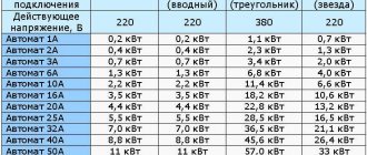
Summing up the indicators, we get 6500 W or 6.5 kilowatts. Next, you will need to refer to the table of machines depending on the connection power.
| Single-phase connection 220 V | Three-phase connection | Machine power | |
| Delta circuit 380 V | Star circuit, 220 V | ||
| 3.5 kW | 18.2 kW | 10.6 kW | 16 A |
| 4.4 kW | 22.8 kW | 13.2 kW | 20 A |
| 5.5 kW | 28.5 kW | 16.5 kW | 25 A |
| 7 kW | 36.5 kW | 21.1 kW | 32 A |
| 8.8 kW | 45.6 kW | 26.4 kW | 40 A |
Based on the standard voltage wiring table, you can select a 32 A device that is suitable for a total power of 7 kW.
If you plan to connect additional equipment, an increase factor is used. The average value of 1.5 is multiplied by the power obtained from the calculations. A reduction factor is applied if it is impossible to operate several electrical appliances at the same time. It is equal to 1 or minus 1.
Table of automatic switches
Devices for shutting off electricity during overloads and short circuits are installed at the entrance to any home network.
It is necessary to correctly calculate the current ratings of circuit breakers, otherwise their operation will be ineffective: either they will not protect lines and household appliances, or false alarms will often occur.
Criterias of choice
It is necessary for its owner to select a circuit breaker based on power for a long and long service, based not only on him. You also need to take into account the brand, price, cable cross-section, current, long-term permissible conductor charge, total power of household equipment, amperage. Be sure to take into account the manufacturer's rated current value with selectivity in the calculation. As a rule, all the necessary information is presented on the unit itself with markings.
Brand and price as criteria for choosing a circuit breaker
By load power
Load power is the amount of energy consumed by all electrical appliances that are connected to the same line. To determine this number, you need to calculate the current load and select a higher current rating or equal to the resulting value.
It should be noted that the value of the electric current in a single-phase network is 5 times higher, and in a three-phase network 2 times higher. That is, each electrical appliance in kilowatts must be multiplied by 5 or 2, and then converted to amperes. The result will be the correct value. You can also use the formula I=P/U*cos φ or special online software that works like a calculator. Often such coefficients are presented in tables on the Internet.
Load power as a selection criterion
By cable cross-section
The cross-section of an electrical cable is the cable cross-sectional area that is capable of withstanding a specific load power without heating. This is a very important parameter, since if the cross section is calculated incorrectly, the entire power line can come out. To calculate this, it is enough to use a special table that shows the cross-section and power for connecting to a network with one, two and three phases. The cross section can also be determined using Ohm's law and summing the maximum power of all equipment.
Note! As a rule, a 3*4 section is chosen for a house. It is important to add up all electrical appliances, even those that are turned on for a short time.
Table of cable cross-sections and power
By short circuit current (SC)
To select a machine based on short-circuit current, it is important to strictly follow the rules of the PUE. At the moment, it is prohibited to use a device with 6 kiloamps. Therefore, systems with 10 kiloamperes are especially common today.
Short circuit current as a selection criterion
According to the long-term permissible current of the conductor
Non-shutdown current is an important parameter when choosing a circuit breaker, since the safe operation of the electrical network will depend on this parameter. It is important to note that it can operate and not turn off when the rated current value exceeds a certain number specified in its technical characteristics. That is, when selecting a device, you need to calculate the power line and take the value with a margin.
You might be interested in Star Triangle Starter
It takes a certain amount of time for the circuit breaker to operate when the load is exceeded. It is regulated by the existing guest from 2010. For example, the average response time is 50 seconds.
Table of permissible current for wires with aluminum conductors
In general, a circuit breaker is equipment whose main task is to ensure the safety of the electrical network from overcurrent with short circuits and overloads. You need to select it according to the power criterion, cable cross-section, minimum and maximum permissible conductor current.
Price
3-pole circuit breakers, depending on the manufacturer, also differ in price. In the table below you can compare the cost of such electrical installation products from the most popular brands in the Russian Federation: IEK, Legrand, Schnider Electric and ABB:
Cost table for 3-pole circuit breakers leading on the Russian market
Video about switch polarity and connection methods
The video will be useful for beginners who want to understand the differences and functionality of single-pole, double-pole, 3-pole and 4-pole circuit breakers. How to connect them correctly and in what cases one or another machine should be used.
Selection of denomination
The choice of circuit breaker rating must meet certain requirements. More specifically, the machine must operate before the currents can exceed the permissible wiring values. It follows from this that the rating of the machine should be slightly less than the current strength that the wiring can withstand.
Selecting the desired AB is quite simple. Moreover, there is a table of current circuit breaker ratings, and this greatly simplifies the task.
Based on all this, you can create an algorithm that makes it easiest to select a machine of the desired denomination:
- For a single section, the cross-section and material of the wire are calculated.
- The value of the maximum current that the cable can withstand is taken from the table.
- All that remains is to use the table to select a machine with a value slightly less than the continuous permissible current.
The table contains five AB ratings 16 A, 25 A, 32 A, 40 A, 63 A, from which the protective device will be selected. Automatic machines with smaller values are practically not used, since the loads of modern consumers simply will not allow this. Thus, having the necessary values, it is very easy to select the machine that corresponds to a particular case.
Calculation of the required denomination
The main protective function of the circuit breaker extends to the wiring, so the rating is selected based on the cable cross-section. In this case, the entire circuit must ensure the normal operation of the devices connected to it. Calculating system parameters is simple, but many nuances must be taken into account in order to avoid errors and problems.
Determination of the total power of consumers
One of the main parameters of the electrical circuit is the maximum possible power of the electricity consumers connected to it. When calculating this indicator, you cannot simply summarize the passport data of devices.
Active and nominal component
For any device powered by electricity, the manufacturer is required to indicate the active power (P). This value determines the amount of energy that will be irrevocably converted as a result of the operation of the device and for which the user will pay on the meter.
But for devices with capacitors or an inductor, there is another power with a non-zero value, which is called reactive (Q). It reaches the device and returns back almost instantly.
The reactive component does not participate in the calculation of used electricity, but together with the active component it forms the so-called “total” or “nominal” power (S), which puts a load on the circuit.
It is necessary to calculate the contribution of an individual device to the total load on the current-carrying conductors and the circuit breaker based on its total power: S = P / cos(f).
Increased starting currents
The next feature of some types of household appliances is the presence of transformers, electric motors or compressors. Such devices consume inrush (starting) current when starting up.
Its value can be several times higher than standard values, but the operating time at increased power is short and usually ranges from 0.1 to 3 seconds. Such a short-term surge will not trigger the thermal release, but the electromagnetic component of the switch, which is responsible for the short-circuit overcurrent, may react.
This situation is especially relevant for dedicated lines to which equipment such as woodworking machines are connected. In this case, you need to calculate the amperage and, perhaps, it makes sense to use a class “D” machine.
Taking into account the demand coefficient
For circuits that have a large amount of equipment connected and no device that consumes the largest portion of the current, use the demand factor (ks). The point of using it is that all devices will not work at the same time, so summing up the rated powers will lead to an overestimated figure.
This coefficient can take a value equal to or less than one. The calculated power (Pr) of each device is calculated using the formula:
Pr = ks * S
The total rated power of all devices is used to calculate the circuit parameters. The use of the demand coefficient is advisable for office and small retail premises with a large number of computers, office equipment and other equipment powered from one circuit.
How do I convert the amp rating of a circuit breaker into power?
This technique is necessary when you know the power of all household appliances that will be connected to the network under the circuit breaker. Manufacturers indicate it in watts (W), so the performance characteristics of the circuit breaker and network parameters are brought to a unified measurement system. The formula used for this is:
P = U*I, where
- P – power value;
- U – supply voltage rating;
- I – current value.
If the calculation is made for a three-phase network circuit breaker, where there are three phases at once, then the power value is calculated using a modified formula, since the value will increase by a constant:
Errors when choosing circuit breakers
There are common mistakes made by inexperienced electricians who do not know how to calculate the power of the machine based on the load :
- The setting is selected only based on the load power, without taking into account the cable cross-section. For example, connect devices with a total current of 14A through a 16A circuit breaker with a 1mm² cable. Despite the fact that both elements allow powering this load, when the current of electrical appliances increases to 16A, the wire insulation will fail, and the circuit breaker will remain on until a short circuit occurs.
- Underrated rated current of the machine. This device protects the cable connected to it, so installing a circuit breaker with a setting of 10A on a wire with a cross-section of 2.5 mm² is impractical; it is better to choose a 16A circuit breaker. This will allow you to turn on additional electrical appliances if necessary.
- Installing an overrated machine for a cable that is not designed for this. For example: 25 Amp circuit breaker and 2.5mm² cable
- Using a “C” series machine to protect the electric motor. In this case, the protection will operate when the electric machine starts.
Purpose and work
The first automatic device designed to protect an electrical circuit from overcurrents was invented by the American scientist studying electromagnetism, Charles Grafton Page in 1836. But only 40 years later a similar design was described by Edison . The modern type of protective devices was patented in 1924 by the Brown, Boveri & Cie corporation from Switzerland.
The innovation of the design is its reusability due to the ability to turn on the module when it is activated by pressing one button. The advantages over fuses were undeniable, and the accuracy of the machine was much better. When using the device in a network designed for 380 volts, all phases are switched off at once. This approach allows you to avoid skewed signal levels and the occurrence of overvoltages.
The direct purpose of a three-phase circuit breaker is to disconnect the line when a short circuit occurs in it or the power consumption of the devices is exceeded. Protection modules belong to the group of switching equipment and, due to their simple designs, ease of use and reliability, they are widely used in both domestic and industrial energy networks. Usually the device involves manual control , but some types are equipped with an electromagnetic or electric motor drive, which makes it possible to control them remotely.
Some users mistakenly assume that the machine protects the devices connected to it, but in fact this is not the case. It does not react in any way to the types and types of devices connected to it, and the only reason for its operation is overload and the appearance of overcurrent. At the same time, if the machine does not turn off the line, the electrical wiring will begin to heat up, which will lead to its damage or even fire.
The choice of an automatic protection module is related to the ability of the electrical line to withstand a current of a certain value, which is directly related to the cable material and its cross-section. In other words, when choosing a module, the main parameter is the power or maximum current that triggers the machine.
Is it worth taking a machine with a reserve?
This is a moot point. On the one hand, the circuit breaker must correspond to the power of the electrical appliance; on the other hand, it must have a small margin so as not to turn off during operation.
As an example, we can cite the same electric boiler with a capacity of 6 kW. Divide 6 kW by 220 volts (mains voltage) and get a value of 27. These are amperes. That is, to connect a 6 kW boiler, you need a 27 Ampere circuit breaker. However, such machines do not exist in nature.
Therefore, here you have to choose between a 25 and 32 Ampere machine. Ideally, of course, so that the boiler does not turn off, you need to install a 32 Ampere machine. But this does not mean that a 25 Ampere machine will not work as expected. It’s just that, given the somewhat reduced power, it may turn off from time to time when the boiler operates at full capacity for a long time.
A little theory
It is known from the physics course that there is a relationship between electrical power, current strength and voltage in the electrical network. In a simplified form, this relationship is expressed by the following formula for a single-phase network:
where W is the current power in watts (W);
I – current strength in amperes (A);
V – voltage in volts (V).
In this case, we will be interested in the current strength, since the circuit breaker and electrical wiring characteristics are often selected based on this parameter. For convenience, we transform the above formula into the expression:
As an example, let’s calculate the current strength for the load that the energy-intensive consumers mentioned above provide to the power grid. Their total power will be about 6 kW, and at a voltage of 220 V we get the current in the circuit:
I = 6000 W / 220 V = 27.3 A
For a three-phase connection diagram, formula (2) will take the following form:
This change is caused by the fact that with an equal load and uniform distribution of power across phases, the current in a three-phase network will be three times less. Thus, with the same total power of 6 kW, but at a voltage of 380 V, the current in the circuit will be equal to:
I = 6000 W / (1.73 x 380 V) = 9.1 A
Having received this indicator, you can begin to select a circuit breaker that provides network overload protection.