Magnetic flux and flux linkage
⇐ PreviousPage 2 of 10Next ⇒
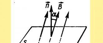
Magnetic flux (or flux of the magnetic induction vector through a given surface Sm
) is called the product of magnetic induction
B
and surface area
Sm
of the field:
| Ф = ВSM. | (6.2) |
Magnetic flux unit: [ F
] = [
B
]
×
[
S
] = Tl
×
m2 = Wb (Weber).
According to Gauss's law for a magnetic field, the total magnetic flux through a closed surface is zero, i.e.
.
In some cases, for example, when current flows in a coil, the magnetic flux is coupled several times with the turns of the coil. To a first approximation, we can assume that all lines of magnetic induction are linked to all turns w
coils.
Then the flux linkage of the coil is related to the flux Ф
by a simple relation:
Y
=
wФ
.
Magnetic field strength
Magnetic field strength is a vector quantity equal to the geometric difference between the magnetic induction divided by the magnetic constant and the magnetization of the substance, i.e. The physical meaning of the vector is determined by the Bio-Savart law: a current element creates at a point located at a distance from the current element (Fig. 6.2), magnetic field with intensity
.
Unit of magnetic field strength
(amps per meter).
The dependence on is usually written in the form
| (6.3) |
where m
0 = 4
p×
10-7 H/m
-
magnetic constant
, magnetic permeability of emptiness; ma = m
0
m
[H/m]
- absolute magnetic permeability of the medium (substance); m = ma
/
m
0 - dimensionless
relative magnetic permeability of a substance, showing how many times the magnetic permeability of the medium (substance) is greater (less) than the magnetic permeability of the void.
Depending on the value of m
distinguish:
diamagnetic materials with magnetic permeability m <
1 (for example, silver, copper, bismuth; they slightly weaken the magnetic field),
paramagnetic materials with m >
1 (for example, platinum, aluminum, air; the magnetic field in them only increases slightly) and ferromagnetic materials with magnetic permeability permeability
m >>
1 (
m »
500…5000).
Magnetization of ferromagnets
Ferromagnetic materials (abbreviated as ferromagnets) include alloys based on iron, nickel, cobalt and other rare earth elements, their compounds; alloys and compounds of manganese, chromium, as well as plastic and other compositions containing ferromagnetic metal powders (ferrites).
The properties of ferromagnetic materials are determined by the value of the absolute magnetic permeability ma
= /, where
ma
=
m
0
m
, and
m
is the relative magnetic permeability of the material.
The most common ferromagnets are alloys based on iron with additives Ni
,
Co
, or cobalt (
Co
) with a coarse-grained structure (with domain grains 10-3 nm in size and a volume of 10-9 ... 10-10 nm3) and with a relative magnetic permeability
m
=
ma
/
m
0 = 500...5000 or more.
In the absence of a magnetic field, the spontaneous magnetization of the domains is randomly oriented and the resulting magnetic field formed by the magnetization of these domains is weak ( B »
0). Under the influence of an external magnetic field, a forced orientation of the magnetization of domains in the direction of the external magnetic field and an increase in the resulting magnetic flux are observed.
It can be assumed that with some large external field () we will obtain the same orientation of the magnetization of all domains (or most of them), and a further increase in the external magnetic flux Ф
and there will be no induction
B = Ф/S
.
This phenomenon is called saturation of ferromagnetic material.
Magnetization curves
Dependence of magnetic induction B
on the magnetic field strength
H
, i.e.
B = f
(
H
), nonlinear (Fig. 6.3) and does not have an analytical expression.
To assess the properties of ferromagnets, magnetization curves B
=
f
(
Н
), given in reference books.
With their help, it is possible for each value of field strength H
to determine the value of magnetic permeability
ma
, which, with increasing field strength, first increases and then decreases.
Hysteresis loop
When alternating current flows in a coil with a ferromagnetic core, magnetization reversal of the core occurs (during each current period), which on the graph looks like a loop - a hysteresis loop (Fig. 6.4, a). If an initially non-magnetized ferromagnet is magnetized to saturation (curve 1), and then the magnetic field strength H (current in the coil) is reduced and then increased again, then the change in induction B will not follow the initial curve: each value of intensity corresponds to two values of magnetic induction depending on whether the field strength increases or decreases.
The magnitude of magnetic induction ±Br, which remains at H = 0, is called residual induction ; The magnetic field strength ±Hc, at which the induction becomes zero, is called coercive force .
In Fig. 6.4 is indicated: ±Hmax and ±Bmax - maximum strength and induction of the magnetic field in a ferromagnet; 2 - the main magnetization curve of a ferromagnet, drawn through the vertices of a family of hysteresis curves (Fig. 6.4, b), each of which corresponds to a certain value of Hmax. The B(H) dependences given in reference books are the main magnetization curves. They differ slightly from the initial magnetization curves.
⇐ Previous2Next ⇒
Recommended pages:
Electromagnetic induction. Flux linkage and coil inductance (definition, formulas).
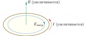
Electromagnetic induction is the phenomenon of the occurrence of electric current in a closed circuit when the magnetic flux passing through it changes.
Electromagnetic induction was discovered by Michael Faraday on August 29, 1831. FLUX LINKAGE - a complete magnetic flux passing through an electrical circuit. For example, the flux linkage of a multi-turn inductor is equal to the sum of the fluxes through all its turns. Unit of measurement - Wb.
An inductor is a helical, helical or helical coil made of a coiled insulated conductor, which has significant inductance with a relatively small capacitance and low active resistance. As a result, when alternating electric current flows through the coil, its significant inertia is observed.
The phenomenon of electromagnetic induction. Law of electromagnetic induction. The magnitude of the induced emf. Rule for determining induced current and EMF.
If a permanent magnet is pushed or pulled into a solenoid that is closed to a galvanometer, then at the moments of its movement or extension we see a deflection of the galvanometer needle (an induced current arises); in this case, the deviations of the arrow when moving the magnet in and out have opposite directions. The greater the speed of movement of the magnet relative to the coil, the greater the deviation of the galvanometer needle. When the poles of the magnet change in the experiment, the direction of deflection of the arrow will also change. To obtain an induction current, you can leave the magnet stationary, then you need to move the solenoid relative to the magnet.
Faraday's law can also be formulated this way: emf.
electromagnetic induction in a circuit is numerically equal and opposite in sign to the rate of change of magnetic flux through the surface bounded by this circuit. Electromotive force (EMF) is a scalar physical quantity that characterizes the work of external forces in direct or alternating current sources.
In a closed conducting circuit, the EMF is equal to the work of these forces to move a single positive charge along the circuit. Electromagnetic induction. Lenz's law (rule) for electromagnetic induction.
Electromagnetic induction, the occurrence of an electromotive force (induction emf) in a conductive circuit located in an alternating magnetic field or moving in a constant magnetic field. The electric current caused by this emf is called induced current. The Joule-Lenz law is a physical law that provides a quantitative assessment of the thermal effect of electric current.
Self-induction. Inductance. Magnetic field energy.
Self-induction is the occurrence of induced emf in a closed conducting circuit [1] when the current flowing through the circuit changes.
When the current in the circuit changes, [2] the magnetic flux through the surface bounded by this circuit changes proportionally [3]. A change in this magnetic flux, due to the law of electromagnetic induction, leads to the excitation of an inductive emf in this circuit.
Inductance (or coefficient of self-induction ) is a coefficient of proportionality between the electric current flowing in any closed circuit and the magnetic flux created by this current through the surface [1], the edge of which is this circuit
Energy Wm of the magnetic field of a coil with inductance L, created by current I.
Definition
The flux linkage is numerically equal to the sum of the magnetic fluxes passing through each turn of the coil, i.e. with the number of turns N
and the same magnetic flux in each turn, the flux linkage can be defined as \Psi = N\Phi_1, where \Phi_1 is the magnetic flux of one turn [ ].
In an ideal solenoid, all magnetic field lines pass through each turn (i.e., do not cross the side surface of the solenoid), and therefore the magnetic flux of each turn is the same. However, in practice, the magnetic fluxes in the turns of the coil are different and the magnitude of the flux linkage is determined by the formula:
\Psi = \sum^{N}_{i=1} {\Phi_i},
where: N is the number of turns; i is the number of the turn with which the flow \Phi_i is linked.
If the coil has a ferromagnetic core, the flux linkage can be determined by the formula:
\Psi = N\Phi_C,
where \Phi_C is the magnetic flux through the magnetic circuit (core) of the coil.
The magnitude of the flux linkage, in addition to the magnetic flux, is related to the current I
in inductance, determined by the expression:
\Psi = IL,
where L is the inductance of the coil [ ].
This formula expresses the principle of continuity in time of the flux linkage of the inductor.