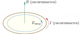
Magnetic flux
Before we talk about electromagnetic induction and self-induction, we need to define the essence of magnetic flux.
Imagine that you picked up a hoop and went outside into the rain. Streams of water will pass through the hoop.
If you hold the hoop horizontally, a lot of water will pass through it. And if you start to turn it, it’s already smaller, because it is not located at a right angle to the vertical.
Now let's place the hoop vertically - not a single drop will pass through it (unless the wind blows, of course).
The magnetic flux is very similar to the flow of water passing through a hoop, only we count the magnitude of the magnetic field passed through the area, not the rain.
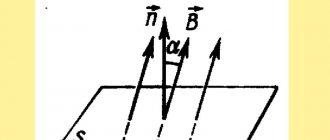
The magnetic flux through the area S of the circuit is a scalar physical quantity equal to the product:
- magnetic induction vector module B ,
- surface area S , which the flow penetrates,
- and the cosine of the angle α between the direction of the magnetic induction vector and the normal vector (perpendicular to the plane of a given surface).
| Magnetic flux Ф - magnetic flux [Wb] B —magnetic induction [T] S – area of the penetrated surface [m2] n — normal vector (perpendicular to the surface) [-] |
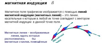
Magnetic flux can be visualized as a value proportional to the number of magnetic lines passing through a given area.
Depending on the angle α , the magnetic flux can be positive ( α < 90° ) or negative ( α > 90° ). If α = 90° , then the magnetic flux is 0.
You can change the magnetic flux by changing the area of the circuit, the field induction module, or the location of the circuit in the magnetic field (by rotating it).
In the case of a non-uniform magnetic field and a non-flat contour, the magnetic flux is found as the sum of the magnetic fluxes penetrating the area of each of the sections into which a given surface can be divided.
Electromagnetic induction
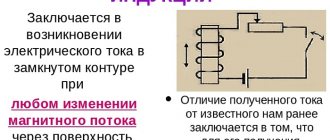
Electromagnetic induction is the phenomenon of the occurrence of current in a closed conducting circuit when the magnetic flux passing through it changes.
The phenomenon of electromagnetic induction was discovered by Michael Faraday through a series of experiments.
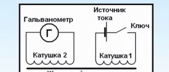
Experience once. Two coils were wound on one non-conducting base in such a way that the turns of one coil were located between the turns of the second. The turns of the first coil were closed to a galvanometer, and the second were connected to a current source.
When the key was closed and current flowed through the second coil, a current pulse arose in the first. When the switch was opened, a current pulse was also observed, but the current through the galvanometer flowed in the opposite direction.
Experience two. The first coil was connected to a current source, and the second to a galvanometer. In this case, the second coil moved relative to the first. As the coil approached or moved away, the current was recorded.
Experience three. The coil was connected to a galvanometer, and the magnet was moved relative to the coil.
Here's what these experiments showed:
- Induction current occurs only when the lines of magnetic induction change.
- The direction of the current differs when the number of lines increases and when they decrease.
- The strength of the induction current depends on the rate of change of the magnetic flux. In this case, both the field itself can change and the circuit can move in a non-uniform magnetic field.
Why does induced current occur?
Current in a circuit can exist when external forces act on free charges. The work done by these forces to move a single positive charge along a closed loop is equal to electromotive force (EMF).
This means that when the number of magnetic lines through the surface limited by the contour changes, an emf appears in it, which is called the induced emf.
STUDYING THE PHENOMENA OF MUTUAL INDUCTION
Instruments:
generator G3 – 112/1, oscilloscope S1 – 117, cassette with two FPE coils – 05/06.
Goal of the work:
study of the phenomenon of mutual induction.
Introduction
1. The phenomenon of electromagnetic induction.
In 1831 The English scientist Faraday discovered the phenomenon of electromagnetic induction: in a closed conducting circuit, an induced current arises when the number of magnetic lines penetrating the area limited by the circuit changes.
The induced emf arising in the circuit obeys Faraday’s law:
those. depends only on the rate of change of the magnetic induction flux F passing through the circuit. According to Lenz's rule, the induced current has such a direction that its magnetic field prevents the change in magnetic flux that caused it.
2. The phenomenon of self-induction.
A current in a closed circuit creates a magnetic field around itself, and this circuit is penetrated by its own magnetic flux F, proportional to the current in the circuit:
Ф = Li
L—self-inductance coefficient or circuit inductance, H.
When the current i changes, the magnetic flux associated with the circuit also changes, then a self-inductive emf appears in the circuit:
If L = const ,
then = - L
The phenomenon of the occurrence of induced emf in the very circuit through which alternating current flows is called self-induction.
3. Mutual induction.
Let's consider two circuits. Circuit 1 is connected to a current source E; using a rheostat R, you can change the current i1 in this circuit.
Current i1 creates a magnetic field around itself, the induction lines of which penetrate circuit 2, closed to a galvanometer.
Ф21 – magnetic flux penetrating circuit 2; Ф21 ~ i1, Ф21 = М21i1. M21 is called the mutual inductance coefficient or the mutual inductance of two circuits. The mutual inductance of the two circuits is numerically equal to the magnetic flux in the second circuit when the current in the first circuit is equal to unity (1 A).
The SI unit of mutual inductance is also called Henry (H)
M = 1 Gn, 1 Gn = BC/A
If you pass current i2 through the second circuit, then now the first circuit will be penetrated by magnetic flux Ф12, proportional to current i2.
F12 = M122. It can be shown that M21 = M12 = M.
The mutual inductance of two circuits depends on the shape, size and relative position of the circuits, as well as on the magnetic permeability of the medium surrounding the circuits.
If the current i1 changes, then the magnetic flux Ф21 will also change, then, according to the law of electromagnetic induction, a mutual induction emf appears in the second circuit:
(if the contours are motionless and non-deformable, M = const). The phenomenon of the occurrence of EMF in one of the circuits when the current strength in the other changes is called mutual induction.
Hence, the mutual inductance of the two circuits is numerically equal to the induced emf arising in one of these circuits, then the current in the other circuit decreases by one per unit of time.
Example 1
Ф21 = 2Ф, where Ф is the magnetic flux of turn 1; the galvanometer will show a surge when the current in the first coil circuit changes.
Example 2
The turns of the second coil cover the first in opposite directions:
Ф21 = Ф – Ф = 0
In the second coil, induced emf does not occur when the current in the circuit changes, which is used in bifilar winding of wires when it is necessary to avoid the occurrence of parasitic induced currents.
In practice, the phenomenon of mutual induction is used in transformers.
Two coils wound on a common steel core form an AC transformer. It was invented by P.N. Yablochkov. in 1876
The transformer is designed to convert alternating voltages and currents.
A variable external emf E1 is connected to the primary winding with the number of turns ω1.
Let's write Ohm's law for it:
where i1 is the current in the primary winding
r1 – its resistance
1 – external EMF
— d (ω1Ф)/dt – self-induction emf in the primary circuit
Ф – magnetic flux through turn 1.
In practice, the voltage drop across resistance r1 is small, therefore
EMF arising in the secondary winding
We get
The ratio of the number of turns in the secondary winding to the number of turns in the primary winding is called the transformation ratio.
If ω2/ω1>1 is a step-up transformer, E2>E1.
If ω2/ω1<1 – step-down transformer.
Transformers are widely used in electrical engineering and radio engineering.
Self-induction
Let's imagine any electrical circuit whose parameters can be changed. If we change the current strength in this circuit - for example, we turn up the rheostat or connect another current source - the magnetic field will change. As a result of this change, an additional induced current will arise in the circuit due to electromagnetic induction, which we discussed above. This phenomenon is called self-induction, and the resulting current is called self-induction current.
| Magnetic flux formula for self-induction F = LI Ф - own magnetic flux [Wb] L - circuit inductance [H] I - current strength in the circuit [A] |
Online preparation for the OGE in physics will help you relieve stress before the exam and get a high score.
Self-induction is the occurrence of an EMF in a conducting circuit, created as a result of a change in current strength in the circuit itself.
Self-induction is somewhat reminiscent of inertia: just as in mechanics it is impossible to instantly stop a moving body, so the current cannot instantly acquire a certain value due to self-induction.
Let's imagine a circuit consisting of two identical lamps connected in parallel to a current source. If we connect a coil in series with the second lamp in this circuit, then when the circuit is closed, the following will happen:
- the first lamp will light up almost immediately,
- the second lamp will light up with a noticeable delay.
When the circuit is opened, the current strength quickly decreases, and the resulting self-induction emf prevents the decrease in magnetic flux. In this case, the induced current is directed in the same way as the original one. The self-induced emf can be many times greater than the external emf. This is why light bulbs burn out so often when the lights go out.
| Self-induced emf ξis — self-induction emf [V] ΔФ/Δt — rate of change of magnetic flux [Wb/s] ΔI/Δt - rate of change of current in the circuit [A/s] L - inductance [H] |
The minus sign in the formula for the law of electromagnetic induction indicates that the induced emf prevents the change in magnetic flux, which causes the emf. When solving calculation problems, the minus sign is not taken into account.
The phenomenon of self-induction and mutual induction. Inductance
The total magnetic flux through the planes of all turns of the coil, created by the current in the same coil, is called the self-induction flux linkage Ym. The occurrence of an emf with any change in the self-induction flux linkage in the coil is called the phenomenon of self-induction .
The flux linkage of the self-induction of the coil is directly proportional to the current strength in it
Ym= Fm×N = L×I, (3.4)
where N is the number of turns of the coil, L is the inductance of the coil.
Inductance is a physical quantity that is numerically equal to the flux linkage of the self-inductance of the circuit when the current in it is equal to 1 A.
Inductance depends on the size and shape of the circuit, as well as on the magnetic properties of the environment.
The unit of inductance (SI) is 1 Henry (H).
Inductance of a long solenoid (solenoid length l
much larger than its diameter D) (Fig. 3.1) is determined by the formula:
, (3.5)
where N is the total number of turns of the solenoid, is the cross-sectional area of the solenoid, m is the relative magnetic permeability of the solenoid core.
If the core is ferromagnetic, then m depends on the magnetic field strength H, and, consequently, on the current strength in the solenoid.
In the case when the solenoid turns are tightly adjacent to each other, the length of the solenoid can be found through the wire diameter d and the total number of turns N:
l
=d∙N. (3.6)
Number of turns per unit length of the solenoid:
. (3.7)
The length of the wire from which the solenoid is wound can be found through the length of one turn and the total number of turns:
l
pr=pD×N. (3.8)
The magnitude of the self-induction emf is determined by the rate of change in the self-induction flux linkage and in the general case is equal to:
. (3.9)
In a particular case, with L=const:
. (3.10)
The phenomenon of self-induction in electrical circuits is similar to inertia in mechanics. When an electrical circuit is closed and opened, the resulting self-induction currents (extracurrents), according to Lenz's rule, are directed so as to prevent a change in the current in the circuit. This leads to the fact that the establishment and disappearance of supercurrent in the circuit does not occur instantly, but gradually.
The law of current change when closing a circuit can be represented as:
, (3.11)
where R is the resistance of the circuit, Iо is the steady-state value of the current in the circuit.
When the current source is turned off, the law of current change looks like this:
. (3.12)
If there are two circuits with currents, then the phenomenon of mutual EMR can be observed. Each of the circuits creates its own magnetic field. Part of the field lines created by the first circuit will intersect the second and vice versa.
The flux linkage of the second circuit, created by the current I1 of the first circuit, is called the flux linkage of mutual induction and is proportional to the strength of the current I1:
Y21=L21×I1. (3.13) Similarly
Y12=L12×I2.
When the current I1 changes in the first circuit, an induced emf occurs in the second circuit
. (3.14)
When current I2 changes in the second circuit, an induced emf occurs in the first circuit
.
Circuits 1 and 2 are called connected , and the phenomenon of the occurrence of induced emf in one of the circuits when the current strength in the other changes is called the phenomenon of mutual EMR . The proportionality coefficients L12=L21 are called the mutual inductance of the circuits. It depends on the size and shape of the circuits, their relative position, as well as on the magnetic properties of the environment. Mutual inductance is numerically equal to the flux linkage of the mutual inductance of one of the circuits with a unit current in the other.
Inductance
Inductance is the ability of a coil, circuit or conductor carrying current to accumulate a magnetic field. It characterizes the ability of a conductor to resist electric current. The easiest way to do this is with a coil, because the coil consists of turns, which are circuits. Remember about magnetic flux and a hoop in the rain - a magnetic flux is created in the circuit. Where there is flux, there is electromagnetic induction.
The inductance of a circuit depends on its shape and size, on the magnetic properties of the environment and does not depend on the current strength in the circuit .
Is it possible to increase the inductance of the coil?
Certainly! You can increase the number of turns, for example. Or place an iron core in the center of the coil.
How does a reel work?
A magnetic field is formed around each conductor through which current flows. If you place a conductor in an alternating field, a current will arise in it.
The magnetic fields of each turn of the coil add up. Therefore, a strong magnetic field arises around the coil through which current flows. When the current in the coil changes, the magnetic flux around it will also change.
Problem once
The figure shows a graph of current versus time in an electrical circuit with an inductance of 1 mH. Determine the self-induction EMF module in the time interval from 15 to 20 s. Express your answer in µV.
Solution
Over a period of 15 to 20 s, the current strength changed from 20 to 0 mA. The self-induction EMF module is equal to:
Answer: the self-induction EMF module from 15 to 20 seconds is 4 μV.
§24. Mutual induction
Mutual induction is the phenomenon of inducing e. d.s. in a conductor or coil when the magnetic flux created by another conductor (coil) changes. E. induced in this way. d.s. it is called e. d.s. mutual induction. An example is the induction of e. d.s. e in the conductor VG (see Fig. 54) when the current i1 in the conductor AB changes, as well as the induction of e. d.s. e2 in coil 2 (see Fig. 55, a) when the current in coil 1 changes.
If two closed circuits or two coils 1 and 2 (Fig. 66) are coupled to a common magnetic flux Ф12, then such circuits and coils are called inductively or magnetically coupled. To assess the degree of their connection, the concept of mutual inductance M was introduced. Mutual inductance, like inductance L, is measured in henry (H).
If the mutual inductance M is known, then e. d.s. The mutual induction em induced in any circuit or coil when the current i changes in another circuit or coil can be obtained from formula (51) for the induced e. d.s. Wherein
em = – M ?i / ?t (55)
Rice. 66. Two inductively coupled coils
Therefore, e. d.s. mutual induction as well as e. d.s. induction itself is proportional to the rate ?i/?t of change in the current creating the magnetic field. In addition, it depends on the number of turns of both coils ?1 and ?2 and on the magnetic resistance of the magnetic circuit connecting them (i.e., on its length l, cross-section s and magnetic permeability). Direction e. d.s. mutual induction is determined by Lenz's rule: it is always directed in such a way that it tends to prevent a change in the current creating it.
Mutual induction makes it possible to connect different electrical circuits through a magnetic field. The phenomenon of mutual induction is widely used in transformers, radio devices and automation devices. However, in some cases, the occurrence of e. d.s. mutual induction is undesirable. For example, e. d.s. mutual inductions induced in communication lines (telephone and telegraph wires) laid along high-voltage power lines or along the contact network of electrified AC railways create interference in the transmission of telephone or telegraph signals. Therefore, communication lines tend to be located perpendicular to the wires of power lines or to be carried out in the form of cable lines protected by metal screens.