- Electrical circuit in closed position
- Ohm's law for a closed circuit
- Physical understanding of Ohm's law for a closed circuit
- Electrical circuit in open position
Definition 1
An electrical circuit is a set of devices connected by wires for the purpose of transmitting, distributing and storing electricity. Devices in electrical circuits are very diverse, and each of them has its own purpose. Electrical circuits were invented to graphically represent electrical circuits.
The main elements of electrical circuits include:
- power supplies;
- wires;
- consumers (receivers);
- protective and switching devices.
Elements of electrical circuits can be active or passive. Passive elements are wires, consumers and capacitors. Motors, batteries that are being charged, and power sources are considered active.
The electrical circuit can be in a closed or open position.
Electrical circuit in closed position
The simplest closed circuit is considered to be the connection between the power source and the receiver by conductors. Conductors must always be insulated.
In order to ensure stable and safe operation of the electrical circuit, auxiliary elements are included in it. These include voltage and current measuring instruments, various switches and switches, as well as other devices.
A closed electrical circuit is divided into two components: internal and external.
Definition 2
The internal component of the electrical circuit is the power source. An external component is a consumer of electricity or a combination of them together with conductors and other devices that operate in a closed electrical circuit.
Current flowing through the lamp filament
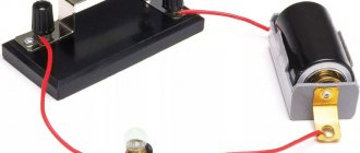
One of the practical and popular uses of electric current is electric lighting. The simplest form of electric lamp is a tiny metal "filament" inside a clear glass bulb that becomes white-hot with thermal energy when enough electric current is passed through it. Like a battery, it has two conductive connection points: one for current input and one for current output. The circuit of an electric lamp connected to a voltage source looks something like this:
Figure 1 – Current through the lamp
When current passes through a thin metal filament of a lamp, it encounters more resistance to movement than in a regular thick piece of wire. This resistance to electric current depends on the type of material, its cross-sectional area and temperature. Technically, this opposition is known as resistance (conductors can be said to have low resistance, while dielectrics have very high resistance). This resistance serves to limit the amount of current flowing through the circuit for a given voltage supplied by the battery, compared to a "short circuit" where we had nothing but a wire connecting one end of the voltage source (battery) to the other. When current moves against the opposition of resistance, "friction" occurs. As with mechanical friction, friction created by current flowing through a resistance manifests itself as heat. The concentrated resistance of the lamp filament causes a relatively large amount of thermal energy to be dissipated into the filament. This thermal energy is enough to cause the filament to become white-hot and begin to glow, while the wires connecting the lamp to the battery (which have much less resistance) are unlikely to become even warm while carrying the same amount of current. As in the case of a short circuit, if the continuity of the circuit is broken at any point, the current stops throughout the circuit. When the lamp is installed, this means that it will stop glowing:
Figure 2 - No current flows through the lamp
As before, no current flows, and at the break points the full potential (voltage) of the battery is available, waiting to connect to cross that break and allow current to flow again. This condition is known as an open circuit, where a break in the circuit prevents current from flowing throughout. All it takes to “open” the circuit is one break. Once any breaks are reconnected and continuity is restored, the circuit is said to be closed.
Ohm's law for a closed circuit
Ohm's law for a closed circuit shows the dependence of current on electromotive force, power source resistance and load resistance.
Is it difficult to figure it out on your own?
Try asking your teachers for help
Solving problems Tests Essays
The current value is equal to the ratio of the source emf to the total value of the external and internal resistance of the circuit. This dependence was empirically derived by the scientist Georg Ohm at the beginning of the 19th century and described it with the following mathematical expression:
\(I= {ε\over R+r},\)
where \(I\) is the current strength;
\(ε\) – EMF of the power source;
\(R\) – external resistance of the circuit;
\(r\) – internal resistance of the source.
To calculate the current strength at a single resistance, use the following expression:
\(I_1 = {ε \over R_1+r};\) \(I_2 = {ε \over R_2+r};\), etc.
After the transformations, the EMF of a closed circuit power source with several external resistances (consumers) will look like this:
\(ε= {I_1 I_2 (R_2-R_1) \over I_2-I_1 }.\)
How does tension arise?
All substances consist of atoms, which are a positively charged nucleus around which smaller negative electrons circle at high speed. In general, atoms are neutral because the number of electrons matches the number of protons in the nucleus.
However, if a certain number of electrons are taken away from the atoms, they will tend to attract the same number, forming a positive field around themselves. If you add electrons, then an excess of them will appear, and a negative field will appear. Potentials are formed - positive and negative.
When they interact, mutual attraction will arise.
Abrahamyan Evgeniy Pavlovich
Associate Professor, Department of Electrical Engineering, St. Petersburg State Polytechnic University
The greater the difference - the potential difference - the stronger the electrons from the material with their excess content will be drawn to the material with their deficiency. The stronger the electric field and its voltage will be.
If you connect potentials with different charges of conductors, an electric current will arise - the directional movement of charge carriers, tending to eliminate the difference in potentials. To move charges along a conductor, the electric field forces perform work, which is characterized by the concept of electric voltage.
Physical understanding of Ohm's law for a closed circuit
A closed circuit can be formed by consumers only in combination with a power source. The current that flows through the consumer returns to the source. That is why the current strength is affected by both the resistance of the consumer and the resistance of the source itself. Accordingly, the total resistance of any closed circuit is equal to the sum of the consumer resistance and the source resistance.
The physical meaning of the dependence of current on EMF and resistance is that with increasing EMF, the energy of charge carriers increases. This means that the speed of their ordered movement increases. However, if the resistance of the circuit increases, their movement slows down, and accordingly, the current decreases.
Electric current flows through a closed circuit; a prerequisite for its uninterrupted movement is reliable connections of all elements.
Did not you find what you were looking for?
Just write and we will help
Power sources in various circuits can be batteries, generators and galvanic cells.
There are also various consumers, mainly lighting devices and motors of various devices.
For a reliable connection, metal wires of various sizes and with different properties are used. I often isolate the conductors from each other.
In order for the current to begin to move through the circuit, two of its points must be connected, and at one of these points there must be an excess of charge carriers. Thus, a potential difference is created between them. The main device that creates this difference is the power source.
Consumers in an electrical circuit are considered loads. Loads create resistance to current flow.
Electric current is used to create artificial lighting. Simple light bulbs are a clear example of a simple closed circuit.
Circuit elements
When comparing the external characteristics of the EMF source Fig. Three-phase circuit power 3.
Classical method for calculating transient processes 5. Depending on the electrical conductivity, all substances are divided into: 1.
Series connection in a circuit A large number of electrical circuits consist of several current receivers.
Matched mode The matched mode of the electrical circuit ensures maximum transfer of active power from the power source to the consumer. In the diagram this element looks like this: In this diagram, real circuit elements are depicted by symbols, and auxiliary circuit elements are usually not depicted, and if the resistance of the connecting wires is much less than the resistance of other circuit elements, it is not taken into account.
Nodal potential method
An ideal current source is assigned an internal resistance tending to an infinitely large value, and a constant current Ik, independent of the voltage at its terminals, equal to the short circuit current, as a result of which an unlimited increase in the load connected to the source is accompanied by a theoretically unlimited increase in voltage and power. An electrical circuit and the electric current flowing through it characterize electromagnetic processes using voltage and current.
There are two types of current: 1. A branch of an electrical circuit of a circuit is a section of a circuit with the same current. Series connection of power supplies of EMF sources is used when it is necessary to create a voltage of the required value, and the operating current in the circuit is less than or equal to the rated current of one EMF source, Fig. Between nodes 1 and 3 there are two parallel branches with emf sources E1 and E2, between nodes 2 and 3 there are also two parallel branches with resistors R1 and R2. This system operation device applies to any electrical household appliance.
For this reason, more rational calculation methods have been developed for the calculation of complex electrical circuits, the main ones are discussed below. The resistance in this electrical circuit is equal to the sum of the resistances of all conductors in the system. When comparing the external characteristics of the EMF source Fig. When one energy receiver has less resistance, more current can pass through it than through other elements of the system.
Classical method for calculating transient processes 5. The arrow in the circle indicates the direction of increasing potential inside the EMF source. Electric current in such an electrical system has several path options. This equation is linear. The chain includes: 1. Kirchhoff's laws - Theory and task
Lecture no. Electric field (page 1)
Lecture No. 1 ELECTRICAL POL E
1.1.
Voltage. Potential.
Potential difference The electromagnetic field consists of an electric field (E) and a magnetic field (H) (Fig. 1.1).
Charged particles create an electric field. Under the influence of an electric field, charges move, forming an electric current. Electric current creates a magnetic field.
| Rice. 1.1 |
Electric field strength
(E) is a vector quantity that characterizes the electric field at each of its points (Fig. 1.1).
The electric voltage between two points
( U)
is equal to the work of field forces to move a unit positive charge from one point in the field to another. Voltage is measured in volts.
Potential
(
f
) is the voltage between any point in the electric field and the ground, the potential of which is conventionally assumed to be zero.
Potential is measured in volts.
The voltage between two points of the electric field (for example, point A
and point
B
in Fig. 1.2) is equal to the potential difference between these points:
U AB
= f A - f B
| fЗ = 0 – ground potential UAZ = = = |
Rice. 1.2
1.2. Electrical capacity. Capacitors
Capacitor
is a system of two conductors (plates) separated by a dielectric, that is, a material that does not conduct electric current (Fig. 1.2).
The symbol for a capacitor is shown in Figure 1.3, a
– a capacitor of constant capacitance,
b
– a variable capacitance.
Rice. 1.2 Capacitor Fig. 1.3 Symbol Fig. 1.4 Paper capacitor
capacitors on circuits
Capacitors have the property of accumulating electric charges Q on their plates of equal magnitude and opposite sign:
Q =
C × U ® ®
where Q
— Charge of each of the capacitor plates,
C;
U
— voltage between plates,
V;
WITH
— capacitance of the capacitor,
F
(Farad).
Capacitance of the capacitor ( C
) depends on the shape and size of its plates (
S
– Fig. 1.2), the distance between them (
d
– Fig. 1.2) and the properties of the dielectric separating the plates. Capacitors are made of paper, mica, ceramic, etc. Paper capacitors (Fig. 1.4) consist of two long strips of aluminum foil insulated with strips of waxed paper.
1.3. Connection of capacitors
For serial connection
the capacitors are connected one after another (for example, in Fig. 1.5 - C1 and C2).
The equivalent (total) capacitance of series-connected capacitors (C) is determined by the formula. For two capacitors.
Rice. 1.5 Sequential Fig. 1.6 Parallel Fig. 1.7 Mixed
connecting capacitors connecting capacitors connecting capacitors
In parallel connection
all positively charged capacitor plates are connected to one point in the circuit, and negatively charged plates are connected to another point (Fig. 1.6). The equivalent capacitance when connecting capacitors in parallel is determined by the formula:
C =
C1 + C2 + C3 ...
Mixed connection of capacitors
- this is a connection in which some of the capacitors are connected in series, and some in parallel (Fig. 1.7).
Equivalent capacitance of series-connected capacitors C1 and C2
: . Equivalent capacitance of parallel connected capacitors C3 and C4: C34 = C3 + C4. Equivalent mixed compound capacity.
Lecture 2 ELECTROMAGNETISM
2.1 Magnetic field
A magnetic field is created by moving charged particles, so there is always a magnetic field around current-carrying conductors.
Magnetic field strength
– a quantity characterizing the intensity of the magnetic field around a conductor without taking into account the magnetic properties of the environment in which current-carrying conductors are located. The magnetic field strength depends only on the strength of the current in the conductor and the distance to the conductor. The further away from the conductor, the lower the strength of the magnetic field created by this conductor.
Rice. 2.1
Magnetic induction (V)
– characterizes the magnitude and direction of the magnetic field, taking into account the magnetic properties of the medium. The magnetic induction vector at any point in the field is depicted tangent to the magnetic field line (Fig. 2.1). The unit of measurement for magnetic induction is Tesla (T).
В = Н× μ0 × μ, where μ0 is the magnetic constant,
μ – magnetic permeability.
Magnetic permeability
(
μ)
– characterizes the magnetic properties of various materials. This is a dimensionless quantity that shows how many times stronger the magnetic field in a given medium is than in a vacuum. For air μ = 1. (only ferromagnetic materials – iron, nickel, cobalt and their alloys – have a high magnetic permeability).
Magnetic constant
μ0 = 4π × 10-7 – magnetic permeability of vacuum.
The direction of the magnetic field lines is determined by the gimlet rule.
Gimlet rule
- if the forward movement of the gimlet coincides with the direction of the current, then the direction of rotation of its handle indicates the direction of the magnetic lines (Fig. 2.2).
Rice. 2.2 Gimlet rule Fig. 2.3 Left hand rule Fig. 2.4 Right hand rule
A current-carrying conductor located in a magnetic field is subject to an electromagnetic force (F), the direction of which is determined by the left-hand rule.
Left hand rule
(Fig. 2.3): if the palm of the left hand is positioned so that the magnetic induction vector enters it, the extended four fingers coincide with the direction of the current, then the thumb of the left hand bent at a right angle indicates the direction of
the electromagnetic force,
which tends to move the conductor.
Electromagnetic force
determined by the formula:
F = B × I × l
where B – magnetic induction, T;
I – current flowing through the conductor, A;
l
– conductor length, m;
A conductor moving in a magnetic field can be considered as a simple electric motor.
Electromagnetic induction
– the phenomenon of the occurrence of electromotive force (EMF) at the ends of a conductor moving in a magnetic field (that is, the mechanical energy of the conductor’s movement is converted into electrical energy). The induced emf is called induced emf. The direction of the induced emf is determined by the right hand rule.
Right hand rule
(Fig. 2.4): the palm of the right hand is positioned so that the magnetic lines enter it, the thumb bent at a right angle is aligned with the direction of movement of the conductor, then the extended four fingers will indicate the direction of the induced EMF.
A wire moving under the influence of mechanical force in a magnetic field can be considered as a simple electrical generator.
2.2 Magnetization of ferromagnets
Ferromagnets
(iron, nickel, cobalt and their alloys with aluminum, copper, chromium, silver) are highly magnetic materials whose magnetic permeability (μ) is much greater than unity.
Electrons in ferromagnets, moving in orbits around the nucleus of an atom, form elementary currents that create separate spontaneously magnetized regions (domains) having different directions of microscopic internal magnetic fields (Fig. 2.6, a). If a ferromagnet is placed in an external magnetic field, then all domains unfold along the external field, that is, the ferromagnet is magnetized (Fig. 2.6, b).
a) b)
| Rice. 2.7 |
| Rice. 2.6 Magnetization of ferromagnets |
Let's place a ferromagnetic core in a coil with current I.
(Fig. 2.7).
The current flowing through the coil creates a magnetic field with intensity H
. The ferromagnetic core under the influence of this field will be magnetized, i.e., magnetic induction B is created in it. If an alternating current with a frequency of 50 Hz flows through the coil (changing in magnitude and direction 50 times per second), then the ferromagnetic core in such a coil will be remagnetized with the same frequency.
| A) |
| b) |
Rice. 2.8 Hysteresis loop Fig. 2.9
Hysteresis loop
(magnetization curve) is a graph of the dependence of the magnetic induction of a ferromagnet -
B
on the magnetic field strength -
H
when the ferromagnet is magnetized (Fig. 2.8).
Sequence of magnetization of a ferromagnet (Fig. 2.8)
1) The magnetization curve starts from zero (point 0), that is, at H = 0, B = 0.
2) With increasing field strength ( N)
, magnetic induction (
B
) grows rapidly (section 0A) and reaches the limiting value +Bm (horizontal section after point A).
3) When H
, magnetic induction
B
also decreases, but more slowly (section AB).
At H = 0, the magnetic induction has the value Br - residual induction.
4) When the direction of the magnetizing current changes, the direction of the field strength also changes (BG section). When H = Ns
(point G)
,
we obtain induction
B
= 0. The value of
Hc
is called
coercive force.
5) With a further increase in H
in the reverse direction (GD section), the magnetic induction will reach the value –Vm – the maximum magnetization of the reverse direction.
6) When H
to zero (section DE), we obtain a decrease
in B
to the value of the residual induction (section
OE).
7) Changing the direction of H again and increasing it (EZhA section), we again obtain the residual induction +Br
The area of the hysteresis loop is proportional to the energy spent on magnetization, therefore ferromagnets with a narrow hysteresis loop are easily remagnetized and vice versa.
Hysteresis losses
- this is the loss of electricity due to heating during magnetization reversal of ferromagnets.
Soft magnetic materials
– these are ferromagnetic materials with a narrow hysteresis loop (Fig. 2.9, a) and low hysteresis losses (commercial iron, low-carbon steel, iron-nickel alloys). They are used for the manufacture of magnetic cores of transformers and electrical machines.
Hard magnetic materials
– these are ferromagnets with a wide hysteresis loop (Fig. 2.9, b), that is, with a large residual induction (Br) (carbon, tungsten, chromium, cobalt steels). Used for the manufacture of permanent magnets.
Lecture 3 DC ELECTRICAL CIRCUITS
3.1. Electrical conductivity
Electricity
– this is the directional movement of charged particles (electrons or ions).
Electrical conductivity
is the property of a substance to create an electric current under the influence of an electric field.
The electrical conductivity of a substance depends on the concentration of charge carriers (the higher the charge concentration, the greater the electrical conductivity). All substances, depending on electrical conductivity, are divided into:
- conductors,
— dielectrics (electrical insulating materials),
- semiconductors.
Conductors
- have high conductivity, these include metals and their alloys, coal, electrolytes (aqueous solutions of salts, acids, alkalis).
Dielectrics
- have negligible conductivity. These include mineral oils, varnishes and a large number of solid non-metallic materials (paper, rubber, glass, ceramics, plastic, wood, etc.).
Semiconductors
- have intermediate conductivity between conductors and dielectrics. These include metals such as silicon, germanium, selenium, metal oxides, etc. The electrical conductivity of semiconductors can be controlled using temperature, light, pressure, voltage, so they are used for the manufacture of various electronic devices (transistors, thyristors, varistors, photocells, etc. .)
3.2. Electric circuit and its elements
To obtain electric current, it is necessary to create a closed electrical circuit (Fig. 3.1).
| Rice. 3.1 Electrical circuit |
Sources of electrical energy
(power supplies) are elements of an electrical circuit that generate electrical energy (in Fig. 3.1 -
E)
.
Receivers of electrical energy
(consumers) are elements of the electrical circuit that consume electricity (in Fig. 3.1 -
R
)
In sources, various types of energy are converted into electrical energy. For example, in electric generators there is mechanical energy, in galvanic cells and batteries there is chemical energy, in photocells the energy of light radiation is converted into electrical energy.
Receivers, on the contrary, convert electrical energy into other types of energy. For example, electric motors convert electrical energy into mechanical energy, electric heating devices into heat, lamps into light, etc.
Electromotive force
–
EMF
(
E
) – equal to the work of external (non-electric) forces in moving a single positive charge along a closed electrical circuit.
3.3. Electrical resistance
When an electric current passes through a conductor, moving free electrons (ions), colliding with atoms or molecules of the conductor, experience resistance to their movement, which characterizes the resistance of the conductor.
Electrical resistance ( R)
– characterizes the properties of a conductor to prevent the passage of electric current. The unit of measurement is Ohm.
The resistance of a conductor depends on the properties of the conductor substance, its length and cross-sectional area and is calculated by the formula:
| Material | Specific resistance, µOhm×m |
| Copper | 0,0175 |
| Aluminum | 0,029 |
| Tungsten | 0,056 |
| Steel | 0,13 — 0,25 |
| Nichrome | 1,1 |
Resistivity (ρ)
is the resistance per unit volume of the conductor material. The unit of measurement is μΩ×m. The resistivity of different conductors does not depend on their dimensions (length and cross-sectional area), but depends only on the material from which the conductor is made.
3.4 Current strength.
Ohm's Law
Current Strength
- equal to the charge passing through the cross section of the conductor per unit time. If charge Q passes through the cross section of the conductor in time t, then the current strength is:
, A (ampere), 1A = 1 C/s.
Ohm's law for a circuit section
- the current strength in the wire is directly proportional to the voltage at its ends and inversely proportional to the resistance of the wire:
. From Ohm's law it follows: , U=
R × I
3.5 Power and energy
The power of electricity receivers is determined by the formula: P = U×I
Power unit – Watt, 1W = 1V×1A
Energy (W) is the power consumed over time: W = Р×t
The unit of energy is Joule. 1J = 1W ×1s. In practice, a unit of 1 kWh is used to account for electricity consumption.
3.6 Joule-Lenz law
When current passes through a conductor, charged particles collide with ions and molecules of the substance. In this case, the conductor heats up.
Joule-Lenz law:
when current passes through a conductor with resistance r, the amount of electrical energy converted into heat in time t is directly proportional to the square of the current strength, the resistance of the conductor and the time of passage of the current:
W = I 2 rt
Heating of conductors is undesirable, since it leads to energy loss. Since the energy spent on heating is proportional to the square of the current, when transmitting electricity over long distances it is advantageous to increase the voltage before transmitting electricity, thereby reducing the current strength.
3.7 Kirchhoff's first law
A node is a point in an electrical circuit at which three or more wires are connected (Figure 3.2).
| I1+ I2 = I3 +I4 + I5 or |
Currents directed towards a node are considered positive, and currents
Rice. 3.2 directed from the node are negative.
Kirchhoff's first law:
The sum of currents directed to a node is equal to the sum of currents directed from the node, i.e., the algebraic sum of currents at a node is zero.
3.8. Connection of resistances - energy receivers
Series connection of resistances
- this is a connection in which the resistances are connected one after the other without branching (Fig. 3.3).
Parallel connection of resistances
is a connection in which one terminal of each resistance is connected to one point in the electrical circuit, and the other terminal of each resistance is connected to another point in the circuit (Fig. 3.4).
Mixed compound
– this is a series-parallel connection (for example, Fig. 3.5).
| Rice. 3.5 Mixed Fig. 3.6 compound |
| Rice. 3.4 Parallel connection |
Rice.
3.3 Serial connection
In a series connection, the same current
I passes through all resistances, the voltage at the terminals of the circuit is equal to the sum of the voltages in all sections of it: U = U1 + U2 + U3, and the equivalent (total) resistance of the circuit R = R1 + R2 + R3
In parallel connection, the voltage across all resistances is the same:
U = U1 = U2 = U3. Current in the unbranched part of the circuit I = I1 + I2 + I3
| Ras. 3 .4 Parallel compound |
The currents on the resistances are determined by Ohm's law: , ,
, where
R is the equivalent resistance of the circuit, determined by the formula: For two parallel-connected resistances, the equivalent resistance
Lecture 4 SINGLE-PHASE AC CIRCUITS
4.1 Basic concepts related to alternating current
Alternating current
is an electric current that periodically changes in magnitude and direction at regular intervals according to a sinusoidal law (Fig. 4.1). Also, voltage and EMF change according to a sinusoidal law.
Period
(T) – the period of time after which the change in current in magnitude and direction is repeated.
During one half cycle
(T/2) the current has one direction, and during the next - the opposite.
Current frequency
— number of periods per second — ,
Rice. 4.1 The unit of frequency is Hertz (Hz). 1Hz = 1/s.
In industrial installations, the current varies according to a sinusoid with a frequency f
= 50 Hz.
Sine wave
is an expanded graph of a rotating vector, therefore sinusoidal currents and voltages are depicted as vectors (Fig. 4.2).
Maximum current and voltage values
(Iм and Uм) are amplitude values (Fig. 4.2).
| Rice. 4.2 |
Instantaneous values of current and voltage ( i, u
)
are the values of current and voltage at an arbitrary moment of time t. For example, the value of current i1
at time t1
Phase
(j) is the angle that determines the position of the current or voltage vector (see Fig. 4.2)
RMS value of alternating current ( I
)
is equal to the value of direct current, which, passing through the same resistance as alternating current, releases the same amount of heat over a period. Effective values are used when calculating alternating current circuits.
, ,
4.2 Resistance in AC circuits
Resistances in AC circuits can be active
and
reactive.
Active resistance
(R) is a resistance that consumes electricity, that is, a resistance in which electrical energy is lost for heating (such heating has a positive value only in electric heating devices).
Reactance
is the resistance of the inductor (L) or capacitor (C). It does not consume electricity.
Capacitance
(XC) is the resistance of the capacitor.
Inductive reactance
(ХL) is the resistance of the coil.
Inductance
(L) is a quantity characterizing the magnetic field created by a coil with current. The inductance of a coil depends on the dimensions of the coil, the number of turns of the coil, and the magnetic properties of the coil core.
4.3 Power in AC circuits
There are total, active and reactive powers.
Active power
(P) represents the power of alternating current, which is similar to the power developed by direct current. It produces useful work; can be converted using electric motors into mechanical power, mechanical energy; measured in watts (W) and determined by the formula:
P = IUcosj,
where j is the phase angle between current and voltage.
called power factor.
Full power
(S) is the maximum amount of active power developed by alternating current when cosj = 1. Total power is measured in volt-amperes (VA) and is calculated by the formula:
S = UI
Reactive power ( QL or
QC) -
characterizes the energy expended to create the magnetic field of an inductance or the electric field of a capacitor. It is consumed from the network, but does not produce useful work.
Q = S×Sinj
4.4 AC circuits with active resistance
The vector diagram shows that in a circuit with active resistance, the current and voltage vectors are in phase (Fig. 4.3).
The effective values of current and voltage are determined by Ohm's law:
Rice. 4.3 Power in a circuit with active resistance is called active power:
P = U×I = I2 ×R.
4.5 AC circuits with inductive reactance
| Rice. 4.4 |
| j |
In Fig.
Figure 4.4 shows a circuit with an inductor whose conductor resistance (active resistance) is so small that it can be considered equal to zero (R = 0). The vector diagram shows that in a circuit with an inductor, the voltage vector leads the current vector by an angle of 90°. That is, the phase angle between current and voltage j = 90°. Coil resistance – X L
=
2πfL, Ohm
| Rice. 4.4 |
Ohm's law for a circuit with inductance: , hence U = UL = I × X L
Reactive power
— QL =
UL × I, var
(volt-ampere reactive)
4.6 AC circuits with active and inductive resistance
| j |
| j |
| j |
| j |
Rice. 4.5 Fig. 4.6
A real coil can be represented as a series inductive connection ( X L)
and active (R) resistance (Fig. 4.5).
The vector diagram shows that the voltage across the active resistance is in phase with the current, and the voltage on the coil leads the current by an angle of 90°. The total voltage (U) is equal to the vector sum of the active and inductive voltages and can be determined using the Pythagorean theorem:
A triangle with sides UL, UR,
U
is called
a stress triangle
(Fig. 4.6, a).
The voltage triangle is similar to the resistance triangle (Fig. 4.6, b) and the power triangle (Fig. 4.6, c). The total resistance is denoted by the letter Z and is determined by the Pythagorean theorem:
, Ohm
| Due to its large volume, this material is placed on several pages: 1 |