DC motor. Connection diagrams and characteristics of DPT
The DC motor has found wide application in various fields of human activity.
Starting from the use of traction drives used in trams and trolleybuses, ending with the drive of rolling mills and lifting mechanisms, where maintaining high precision of rotation speed is required. The main positive features that distinguish a DPT from an asynchronous motor:
| — flexible starting and adjustment characteristics; |
| — two-zone regulation, which allows you to achieve rotation speeds of more than 3000 rpm. |
Negative features:
| - difficulty in manufacturing and high cost; |
| — during operation, constant maintenance is necessary, since the collector and current-collecting brushes have a short service life. |
A DC motor is used only when the use of an AC motor is impossible or extremely impractical. On average, for every 70 AC motors there is only 1 DC motor.
DPT design
The DC motor consists of:
| — inductor (stator); |
| - armature (rotor); |
| — collector; |
| — current collection brushes; |
| — structural elements. |
The armature and the inductor are separated by an air gap. The inductor is a frame that serves to secure the main and additional poles of the motor’s magnetic system. The main poles have excitation windings, and the additional poles have special windings that help improve switching.
The collector supplies direct current to the working winding, which is placed in the slots of the rotor. The collector has the form of a cylinder and consists of plates isolated from each other; it is mounted on the engine shaft. The brushes are used to remove current from the commutator; they are mounted in brush holders to ensure the correct position and reliable pressure on the surface of the commutator.
Figure 1 – DC motor design
DC motors are classified according to the stator magnetic system:
1) DFC with permanent magnets;
2) DFC with electromagnets:
| — DPT with independent excitation; |
| — DBT with sequential excitation; |
| — DPT with parallel excitation; |
| — DBT with mixed arousal. |
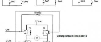
Figure 2 – DC motor connection diagrams
The connection diagram of the stator windings significantly affects the electrical and traction characteristics of the drive.
Starting a DC Motor
The DC motor is started using starting rheostats, which are active resistances connected to the armature circuit. Rheostatic starting is performed for two reasons:
| — if necessary, smooth acceleration of the electric motor; |
| - at the initial moment of time, the starting current Iп = U / Rя is very large, which causes overheating of the armature winding (which has low resistance). |
Only DFCs with a power of up to 1 kW are allowed to start without starting rheostats, the so-called “direct start”.
Figure 3 – Rheostatic engine starting with 3 stages
At the beginning of the start-up, all resistances are connected to the rotor circuit, and as the speed increases, they are removed in steps.
Rotation speed regulation
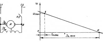
The rotational speed of a DC motor is expressed by the formula:
This expression is also called the electromechanical characteristic of the DPT, in which:
| U – supply voltage; |
| Iа – current in the armature winding; |
| Rya – anchor chain resistance; |
| k – motor design coefficient; |
| Ф – magnetic flux of the motor. |
Engine torque formula:
Substituting the electromechanical characteristics into the formula, we get:
Thus, based on the above formulas, we conclude that the rotation speed of the DC motor can be adjusted by changing the armature resistance, supply voltage and magnetic flux.
DC Motor Design and Maintenance
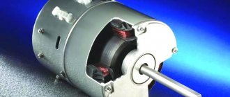
The main winding of a DC motor is the armature , which is connected to the power source through a brush apparatus . The armature rotates in a magnetic field created by the stator poles (field windings) . The end parts of the stator are covered with shields with bearings in which the motor armature shaft rotates. fan is installed on the same shaft , driving a flow of air through the internal cavities of the engine during operation.
DC Motor Diagram
The brush apparatus is a vulnerable element in the engine design. The brushes are ground to the commutator in order to repeat its shape as accurately as possible, and are pressed against it with constant force. During operation, the brushes wear out, conductive dust from them settles on the stationary parts, and must be removed periodically. The brushes themselves must sometimes be moved in the grooves, otherwise they get stuck in them under the influence of the same dust and “hang” above the commutator. The characteristics of the motor also depend on the position of the brushes in space in the plane of rotation of the armature.
Over time, brushes wear out and need to be replaced. The commutator at the points of contact with the brushes also wears out. Periodically, the armature is dismantled and the commutator is turned on a lathe. After grinding, the insulation between the commutator lamellas is cut to a certain depth, since it is stronger than the commutator material and will destroy the brushes during further processing.
Three-phase brushless DC motor
This type of motor has excellent characteristics, especially when controlled by position sensors. If the resistive torque varies or is completely unknown, or if it is necessary to achieve a higher starting torque, sensor control is used. If the sensor is not used (usually in fans), the control allows you to do without wired communication.
Features of controlling a three-phase brushless motor without a position sensor:
- the rotor location is determined using a differential ADC (analog-to-digital converter);
- current overload is also determined using an ADC (analog-to-digital converter) or an analog comparator;
- speed adjustment is performed using PWM channels connected to the lower drivers;
- AT90PWM3 and ATmega64 are considered recommended microcontrollers;
- The supported communication interfaces (communication interfaces) are UART, SPI and TWI.
Features of controlling a three-phase brushless motor with a position sensor using the example of a Hall sensor:
- speed adjustment is performed using PWM channels connected to the lower drivers;
- the output of each of the Hall sensors is connected to the corresponding I/O line of the microcontroller, configured to generate interrupts when the state changes;
- supported communication interfaces (communication interfaces) are UART, SPI and TWI;
- current overload is determined using an ADC (analog-to-digital converter) or an analog comparator.
Electric motor device
The main elements that make up a typical three-phase motor are:
- A housing having legs with which it is attached to the foundation;
- A stator whose structure resembles a simple transformer. It has a core and a winding. When current is applied, a vortex electromagnetic field is created.
- Rotor. Main rotating part.
- The shaft on which the rotor is rigidly mounted. The front part extends outward and has a keyway for gears or a pulley. An impeller for cooling and airflow is mounted on the rear part, extending beyond the body.
- Bearings located in the niches of the front and rear covers.
- Sealed terminal box.
Classification of MPT according to the method of powering the inductor and armature windings
Based on this feature, MPTs are divided into 4 types.
With independent excitation
The inductor and armature windings have no electrical connection. In generators of this type, the excitation winding is powered by a direct current network, a battery, or a generator specially designed for this purpose - an exciter. The power of the latter is several hundredths of the power of the main generator.
Scope of application of generators with independent excitation:
- systems of significant power, where the voltage on the excitation winding differs significantly from the generated one;
- systems for regulating the rotation speed of engines powered by generators.
For motors with independent excitation, the armature winding is also energized. Basically these are also high-power units.
The independence of the inductor winding makes it more convenient and economical to regulate the excitation current. Another feature of such motors is the constancy of the excitation magnetic flux under any load on the shaft.
With parallel excitation
The inductor and armature windings are connected in one circuit parallel to each other. Generators of this type are usually used for medium power. In a parallel connection, the voltage generated by the device is applied to the excitation winding. When the inductor and armature windings are connected into one circuit, they speak of a self-excited generator.
In terms of their characteristics, they are identical to motors with independent excitation and have the following features:
- when the load changes, the rotation speed is practically not transformed: the deceleration is no more than 8% when transferring from idle to rated load;
- it is possible to regulate the rotation speed with minimal losses, and within a wide range - 2 times, and for specially designed motors, 6 times.
The inductor of a rotating parallel-wound motor cannot be disconnected from the armature circuit, even if it is already disconnected. This will lead to the induction of a significant EMF in the excitation winding with subsequent failure of the motor. Personnel nearby may be injured.
With sequential excitation
The windings are connected in series to each other. The armature current flows through the field winding. Generators of this type are almost never used, since the process of self-excitation occurs quite rapidly and the device is not able to provide the constant voltage required by most consumers. They are used only in special installations.
Series excitation circuit
Motors of this type are widely used as traction motors (electric locomotives, trolleybuses, cranes, etc.): compared with parallel excitation analogues, when loaded they produce a higher torque with a simultaneous decrease in rotation speed. The starting torque is also high.
Starting the engine with a load below 25% of the rated load, and even more so at idle, is unacceptable: the rotation speed will be too high and the unit will fail.
With parallel-series (mixed) excitation
There are two types of scheme:
- the main winding of the inductor is connected in parallel with the armature winding, the auxiliary winding is connected in series;
- The main winding of the inductor is connected in series with the armature winding, the auxiliary winding is connected in parallel.
Schemes of MPT excitation systems
Connecting a parallel winding before a series winding is called a “short shunt”, and after a series winding - a “long shunt”. Generators of this type are used extremely rarely.
The engines combine the advantages of analogues with parallel and series excitation: they are able to operate at idle speed and at the same time develop significant traction force. But they are almost never used today.
Connecting a DC motor to a 220 network
DC motors are not used as often as AC motors. Below are their advantages and disadvantages.
| Advantages | Flaws _ |
| rotation speed is easily adjustable | high price |
| soft start and smooth acceleration | design complexity |
| obtaining rotation speed above 3000 rpm | difficulty in operation |
In everyday life, DC motors are used in children's toys, since they are powered by batteries. They are used in transport: in the subway, trams and trolleybuses, and cars. In industrial enterprises, DC electric motors are used to drive units that use batteries for uninterrupted power supply.
DC Motor Design and Maintenance
The main winding of a DC motor is the armature , which is connected to the power source through a brush apparatus . The armature rotates in a magnetic field created by the stator poles (field windings) . The end parts of the stator are covered with shields with bearings in which the motor armature shaft rotates. fan is installed on the same shaft , driving a flow of air through the internal cavities of the engine during operation.
DC Motor Diagram
The brush apparatus is a vulnerable element in the engine design. The brushes are ground to the commutator in order to repeat its shape as accurately as possible, and are pressed against it with constant force. During operation, the brushes wear out, conductive dust from them settles on the stationary parts, and must be removed periodically. The brushes themselves must sometimes be moved in the grooves, otherwise they get stuck in them under the influence of the same dust and “hang” above the commutator. The characteristics of the motor also depend on the position of the brushes in space in the plane of rotation of the armature.
Over time, brushes wear out and need to be replaced. The commutator at the points of contact with the brushes also wears out. Periodically, the armature is dismantled and the commutator is turned on a lathe. After grinding, the insulation between the commutator lamellas is cut to a certain depth, since it is stronger than the commutator material and will destroy the brushes during further processing.
DC motor connection circuits
The presence of field windings is a distinctive feature of DC machines. The electrical and mechanical properties of the electric motor depend on the way they are connected to the network.
The excitation winding is connected to an independent source. The characteristics of the motor are the same as those of a permanent magnet motor. The rotation speed is controlled by the resistance in the armature circuit. It is also regulated by a rheostat (adjusting resistance) in the excitation winding circuit, but if its value decreases excessively or if it breaks, the armature current increases to dangerous values. Motors with independent excitation cannot be started at idle speed or with a low load on the shaft. The rotation speed will increase sharply and the motor will be damaged.
Independent excitation circuit
The remaining circuits are called self-excited circuits.
The rotor and excitation windings are connected in parallel to one power source. With this connection, the current through the excitation winding is several times less than through the rotor. The characteristics of electric motors are rigid, allowing them to be used to drive machines and fans.
Regulation of the rotation speed is ensured by the inclusion of rheostats in the rotor circuit or in series with the excitation winding.
Parallel excitation circuit Series excitation
The field winding is connected in series with the armature winding, and the same current flows through them. The speed of such an engine depends on its load; it cannot be turned on at idle. But it has good starting characteristics, so a series excitation circuit is used in electrified vehicles.
Series excitation circuit Mixed excitation
With this scheme, two excitation windings are used, located in pairs on each of the poles of the electric motor. They can be connected so that their flows are either added or subtracted. As a result, the motor can have characteristics similar to a series or parallel excitation circuit.
Mixed excitation circuit
To change the direction of rotation, change the polarity of one of the field windings. To control the start of the electric motor and its rotation speed, stepwise switching of resistances is used.
Rate the quality of the article. Your opinion is important to us:
In order to figure out how to connect a specific type of electric motor, you need to understand the principles of its operation and design features. There are many different types of electric motors. Depending on the method of connection to the AC network, they are three-phase, two-phase or single-phase. According to the method of power supply, the rotor windings are divided into synchronous and asynchronous.
The principle of operation of an electric motor demonstrates the simplest experiment that we were all shown at school - the rotation of a frame with current in the field of a permanent magnet.
The frame with current is an analogue of the rotor, the stationary magnet is the stator. If current is applied to the frame, it will turn perpendicular to the direction of the magnetic field and freeze in this position. If you force the magnet to spin, the frame will rotate at the same speed , that is, synchronously with the magnet. We have a synchronous electric motor. But our magnet is a stator, and by definition it is motionless. How to make the magnetic field of a stationary stator rotate?
First, let's replace the permanent magnet with a current-carrying coil. This is the winding of our stator. As is known from the same school physics, a coil with current creates a magnetic field. The latter is proportional to the magnitude of the current, and the polarity depends on the direction of the current in the coil. If we apply alternating current to the coil, we get an alternating field.
Magnetic field is a vector quantity. The alternating current in the supply network has a sinusoidal shape.
A very clear analogy with a clock will help us. What vectors constantly rotate before our eyes? These are the hour hands . Let's imagine that there is a clock hanging in the corner of the room. The second hand rotates one full revolution per minute. An arrow is a vector of unit length.
The shadow that the arrow casts on the wall varies as a sine with a period of 1 minute, and the shadow cast on the floor changes as a cosine. Or a sine phase shifted by 90 degrees. But a vector is equal to the sum of its projections. In other words, the arrow is equal to the vector sum of its shadows.
Two-phase synchronous electric motor
Let's place two windings on the stator at an angle of 90 degrees, that is, mutually perpendicular. Let us supply them with sinusoidal alternating current. The phases of the currents will be shifted by 90 degrees . We have two mutually perpendicular vectors, varying according to a sinusoidal law with a phase shift of 90 degrees. The sum vector will rotate in a clockwise manner, making one complete revolution per period of the alternating current frequency.
We have a two-phase synchronous electric motor. Where can I get the phase-shifted currents to power the windings? Probably not everyone knows that in the beginning AC distribution networks were two-phase. And only later, not without a struggle, did they give way to three-phase ones. If we had not given in, our two-phase electric motor could have been connected directly to two phases.
But three-phase networks won, for which three-phase electric motors were developed. And two-phase electric motors have found their application in single-phase networks in the form of capacitor motors.
Three-phase synchronous motor
Modern AC distribution networks are made according to a three-phase circuit.
- Three sinusoids are transmitted over the network at once of a third of a period or 120 degrees relative to each other.
- A three-phase motor differs from a two-phase one in that it has not two, but three windings on the stator, rotated 120 degrees.
- Three coils connected to three phases create a total rotating magnetic field that turns the rotor.
Three-phase asynchronous motor
Current is supplied to the rotor of a synchronous motor from a power source. But we know from the same school physics that a current in a coil can be created by an alternating magnetic field. You can simply short the ends of the coil to the rotor. You can even leave just one turn, like in a frame. And let the current induce a rotating magnetic field of the stator.
- At the moment of start, the rotor is stationary, and the stator field rotates.
- The field in the rotor circuit changes, inducing an electric current.
- The rotor will begin to catch up with the stator field. But it will never catch up, since in this case the current will cease to be induced in it.
- In an asynchronous motor, the rotor always rotates slower than the magnetic field.
- The difference in speed is called slip. Connecting an asynchronous motor does not require current to be supplied to the rotor winding.
Synchronous and asynchronous motors have their own advantages and disadvantages, but the fact is that the majority of motors used in industry today are three-phase asynchronous motors.
Single-phase asynchronous electric motor
If we leave a short-circuited coil on the rotor and one coil on the stator, we will get an amazing design - an asynchronous single-phase motor.
At first glance, it seems that such an engine should not work. After all, there is no current in the rotor , and the magnetic field of the stator does not rotate. But if you push the rotor by hand in any direction, the engine will start! And it will rotate in the direction in which it was pushed at launch.
The operation of this motor can be explained by imagining the stationary alternating magnetic field of the stator as the sum of two fields rotating towards each other. While the rotor is stationary, these fields balance each other, so a single-phase asynchronous motor cannot start on its own. If the rotor is set in motion by an external force, it will rotate in parallel with one vector and towards the other.
A passing vector will pull the rotor along with it, a counter vector will slow it down.
It can be shown that due to the difference between the head and tail speeds, the influence of the tail vector will be stronger, and the engine will operate in asynchronous mode.
It is possible to connect loads to a three-phase network using two circuits - star and delta. When connected by a star, the beginnings of the windings are connected to each other, and the ends are connected to the phases. When switched on in a triangle, the end of one winding is connected to the beginning of the other.
In a star connection circuit, the windings are under a phase voltage of 220 V; when connected in a delta, they are under a linear voltage of 380 V.
When switched on by a triangle, the motor develops not only more power, but also large starting currents. Therefore, sometimes they use a combined scheme - starting with a star, then switching to a triangle.
The direction of rotation is determined by the order in which the phases are connected. To change the direction, it is enough to swap any two phases.
Connection to a single-phase network
A three-phase motor can be connected to a single-phase network, although with a loss of power, if one of the windings is connected through a phase-shifting capacitor. However, when turned on in this way, the engine loses a lot of its parameters, so this mode is not recommended.
220 volt connection
Unlike a three-phase motor, a two-phase motor is initially designed to be connected to a single-phase network. To obtain a phase shift between the windings, a working capacitor is switched on, which is why two-phase motors are also called capacitor motors.
The capacity of the working capacitor is calculated using formulas for the nominal operating mode. But when the mode differs from the nominal one, for example, during startup, the balance of the windings is disrupted . To ensure the starting mode during start and acceleration, an additional starting capacitor is connected in parallel to the working one, which must be turned off when reaching the rated speed.
How to turn on a single-phase asynchronous motor
If automatic starting is not needed, an asynchronous single-phase motor has the simplest switching circuit. A feature of this type is the impossibility of automatic start.
For automatic starting, a second starting winding is used, as in a two-phase electric motor. The starting winding is connected through the starting capacitor only for starting and after that must be turned off manually or automatically.
Pros - cons
The technical characteristics of asynchronous electric motors with a squirrel-cage rotor are so superior to those of synchronous ones that most drives are made on their basis.
The advantages of such devices are:
- Reliability, simplicity of design, durability;
- No difficulties in repair and maintenance;
- By switching 2 phases, you can make the shaft rotate in the opposite direction;
- Application as a generator.
There are also disadvantages or disadvantages:
- If the phasing is incorrect, the shaft can rotate in the wrong direction and jam other mechanics (gears);
- Inrush current up to five times the rated current;
- Acceleration and braking speed. Some devices with high inertia require higher power motors.
- If a phase is broken, the motor may burn out if the voltage supply is not turned off in a timely manner.
Connection to single-phase and three-phase power supplies
According to the type of supply network, AC electric motors are classified into single- and three-phase.
Connecting asynchronous single-phase motors is very easy - to do this, just connect the phase and neutral wires of a single-phase 220V network to the two outputs on the housing. Synchronous motors can also be powered from this type of network, but the connection is a little more complicated - it is necessary to connect the rotor and stator windings so that their single-pole magnetization contacts are located opposite each other.
Connecting to a three-phase network seems a little more complicated
First of all, you should pay attention that the terminal box contains 6 pins - a pair for each of the three windings. Secondly, this makes it possible to use one of two connection methods (“star” and “delta”)
Incorrect connection can damage the motor by melting the stator windings.
The main functional difference between “star” and “triangle” is the different power consumption, which is done to enable the machine to be connected to three-phase networks with different line voltages - 380V or 660V. In the first case, the windings should be connected in a “triangle” pattern, and in the second case, in a “star” pattern. This switching rule allows in both cases to have a voltage of 380V on the windings of each phase.
On the connection panel, the winding terminals are located in such a way that the jumpers used for switching on do not cross each other. If the motor terminal box contains only three terminals, then it is designed to operate on one voltage, which is indicated in the technical documentation, and the windings are interconnected inside the device.
Connection diagrams for single-phase asynchronous motors
With starting winding
To connect a motor with a starting winding, you will need a button in which one of the contacts opens after switching on. These opening contacts will need to be connected to the starting winding. In stores there is such a button - this is PNDS. Its middle contact closes for the holding time, and the two outer ones remain in a closed state.
What kind of lighting do you prefer?
Built-in Chandelier
First, using measurements, we determine which winding is working and which is starting. Typically the output from the motor has three or four wires.
Consider the option with three wires. In this case, the two windings are already combined, that is, one of the wires is common. We take a tester and measure the resistance between all three pairs. The working one has the lowest resistance, the average value is the starting winding, and the highest is the common output (the resistance of two windings connected in series is measured).
If there are four pins, they ring in pairs. Find two pairs. The one with less resistance is the working one, the one with more resistance is the starting one. After this, we connect one wire from the starting and working windings, and bring out the common wire. A total of three wires remain (as in the first option):
We work further with these three wires - we use them to connect a single-phase motor.
Condenser
When connecting a single-phase capacitor motor, there are options: there are three connection diagrams and all with capacitors. Without them, the engine hums, but does not start (if you connect it according to the diagram described above).
Circuit with two capacitors
When implementing other circuits - with one capacitor - you will need a regular button, machine or toggle switch. Everything connects there simply.
Selection of capacitors
There is a rather complex formula by which you can calculate the required capacity accurately, but it is quite possible to get by with recommendations that are derived from many experiments:
The operating voltage of these capacitors should be 1.5 times higher than the network voltage, that is, for a 220 volt network we take capacitors with an operating voltage of 330 V and higher. To make starting easier, look for a special capacitor for the starting circuit. They have the words Start or Starting in their markings, but you can also use regular ones.
Changing the direction of motor movement
If, after connecting, the motor works, but the shaft does not rotate in the direction you want, you can change this direction. This is done by changing the windings of the auxiliary winding. When assembling the circuit, one of the wires was fed to the button, the second was connected to the wire from the working winding and the common one was brought out. This is where you need to switch the conductors.
Current Applications and Prospects
There are many devices for which increasing uptime is critical. In such equipment, the use of BDKP is always justified, despite their relatively high cost. These can be water and fuel pumps, cooling turbines for air conditioners and engines, etc. Brushless motors are used in many models of electric vehicles
Currently, the automotive industry is seriously paying attention to brushless motors.
BDKPs are ideal for small drives operating in difficult conditions or with high precision: feeders and belt conveyors, industrial robots, positioning systems. There are areas in which brushless motors dominate without alternative: hard drives, pumps, silent fans, small household appliances, CD/DVD drives. The low weight and high power output have also made the BDKP the basis for the production of modern cordless hand tools.
Principle of operation
The operation of the engine is that the controller switches a certain number of stator windings in such a way that the vector of the magnetic fields of the rotor and stator are orthogonal. Using PWM (pulse width modulation), the controller controls the current flowing through the motor and regulates the torque exerted on the rotor. The direction of this acting moment is determined by the mark of the angle between the vectors. Electrical degrees are used in calculations.
In such a situation, the resulting vector shifts and becomes stationary with respect to the rotor flow, which, in turn, creates the necessary torque on the electric motor shaft.
Classification
All three-phase electric motors can be divided into two groups:
Synchronous. They rotate at the speed of a constant magnetic field. To increase power, the rotor is made according to the principle of a transformer - it has windings and a core. Voltage is supplied through carbon brushes to the commutator rings (contacts) mounted on the shaft, and only then to the rotor coils.
Asynchronous, with a squirrel-cage rotor. The rotational impulse comes from the excitation of the stator coils. The short-circuited turns are made in the form of a squirrel wheel. The rotor rotates at a speed lower than the electromagnetic field of the stator. Hence its name.
Energy conversion principle
The operating principle of any type of electric motor is to use electromagnetic induction that occurs inside the device after being connected to the network. In order to understand how this induction is created and sets the engine elements in motion, you should turn to a school physics course that explains the behavior of conductors in an electromagnetic field.
So, if we immerse a conductor in the form of a winding, along which electric charges move, into a magnetic field, it will begin to rotate around its axis. This is due to the fact that the charges are under the influence of a mechanical force that changes their position on a plane perpendicular to the magnetic field lines. We can say that the same force acts on the entire conductor.
The diagram below shows a current-carrying loop that is energized and two magnetic poles that give it rotational motion.
The picture is clickable.
It is this pattern of interaction between the magnetic field and the current-carrying circuit with the creation of electromotive force that underlies the functioning of electric motors of all types. To create similar conditions, the device design includes:
- Rotor (winding) is a moving part of the machine, mounted on a core and rotation bearings. It plays the role of a current-conducting rotational circuit.
- The stator is a stationary element that creates a magnetic field that affects the electric charges of the rotor.
- Stator housing. Equipped with mounting sockets with cages for rotor bearings. The rotor is placed inside the stator.
To represent the design of an electric motor, you can create a circuit diagram based on the previous illustration:
After connecting this device to the network, a current begins to flow through the rotor windings, which, under the influence of the magnetic field arising on the stator, gives the rotor rotation, which is transmitted to the rotating shaft. Rotation speed, power and other performance indicators depend on the design of the specific motor and the parameters of the electrical network.
Working principle of DC motor
The operation of all modern electric motors is based on the principles of electromagnetic induction and the so-called “right hand rule”, when the rotor begins to rotate when multidirectional current is passed at the top and bottom of the rotor winding. According to this rule, the conductors laid in the armature grooves are pushed out of the magnetic field generated by the stator, thereby accelerating the rotor of the electric motor.
It turns out that the upper part of the rotor winding begins to be pushed to the left, and the lower part to the right. This energy is transferred directly to the shaft of the electric motor, around which the winding is fixed, and it rotates. However, rotation stops when the rotor is turned and the armature parts are swapped. To maintain speed in the electric DC motor P, a commutator is used, with the help of which the rotor winding is switched.
Now let's look at the most common ways to connect a DC motor. Please note that the optimal connection to the network or battery must correspond to the power of the power unit. There are devices of low, medium and high power.
Types of engines and their design
AC electric motors have a different design, thanks to which it is possible to create machines with the same rotor speed relative to the stator magnetic field, and machines where the rotor “lags behind” the rotating field. According to this principle, these motors are divided into corresponding types: synchronous and asynchronous.
Asynchronous
The design of an asynchronous electric motor is based on a couple of important functional parts:
- The stator is a cylindrical block made of steel sheets with grooves for laying conductive windings, the axes of which are located at an angle of 120˚ relative to each other. The poles of the windings go to the terminal box, where they are connected in different ways, depending on the required operating parameters of the electric motor.
- Rotor. In the design of asynchronous electric motors, two types of rotors are used:
- Short-circuited. So called because it is made from several aluminum or copper rods short-circuited using end rings. This design, which is a current-carrying rotor winding, is called a “squirrel cage” in electromechanics.
- Phase. On rotors of this type, a three-phase winding is installed, similar to the stator winding. Most often, the ends of its conductors go to the terminal pad, where they are connected in a star, and the free ends are connected to slip rings. The phase rotor allows you to use brushes to add an additional resistor to the winding circuit, which allows you to change the resistance to reduce inrush currents.
In addition to the described key elements of an asynchronous electric motor, its design also includes a fan for cooling the windings, a terminal box and a shaft that transmits the generated rotation to the working mechanisms of the equipment whose operation is provided by this motor.
The operation of asynchronous electric motors is based on the law of electromagnetic induction, which states that electromotive force can only arise under conditions of a difference in the speed of rotation of the rotor and the magnetic field of the stator. Thus, if these speeds were equal, the EMF could not appear, but the influence on the shaft of such “braking” factors as load and bearing friction always creates conditions sufficient for operation.
Synchronous
The design of synchronous AC electric motors is somewhat different from the design of asynchronous analogues. In these machines, the rotor rotates around its axis at a speed equal to the rotation speed of the stator's magnetic field. The rotor or armature of these devices is also equipped with windings, which are connected at one end to each other and at the other to a rotating collector. The contact pads on the commutator are mounted in such a way that at a certain point in time it is possible to supply power through the graphite brushes to only two opposite contacts.
Operating principle of synchronous electric motors:
- When the magnetic flux in the stator winding interacts with the rotor current, a torque arises.
- The direction of movement of the magnetic flux changes simultaneously with the direction of the alternating current, due to which the rotation of the output shaft is maintained in one direction.
- The desired rotation speed is adjusted by adjusting the input voltage. Most often, in high-speed equipment, such as rotary hammers and vacuum cleaners, this function is performed by a rheostat.
The most common reasons for failure of synchronous electric motors are:
- wear of the graphite brushes or weakening of the pressure spring;
- wear of shaft bearings;
- collector contamination (clean with sandpaper or alcohol).
Three Phase Alternator
Design and principle of operation
Modern DC transformers use the same principle of interaction of a charged conductor with a magnetic field. With the improvement of technology, the device is only supplemented with some elements that improve performance. For example, nowadays permanent magnets are used only in low-power motors, since in large devices they would take up too much space.
The basic principle
The initial prototypes of engines of this type were noticeably simpler than modern devices. Their primitive device included only a stator of two magnets and an armature with windings to which current was supplied. Having studied the principle of interaction of magnetic fields, the designers determined the following engine operation algorithm:
- The supply of power creates an electromagnetic field on the armature windings.
- The poles of the electromagnetic field are repelled from the same poles of the permanent magnet field.
- The armature, together with the shaft on which it is attached, rotates in accordance with the repelling field of the winding.
This algorithm worked perfectly in theory, but in practice, the creators of the first engines faced characteristic problems that impeded the functioning of the machine:
- The dead position from which the engine cannot be started is when the poles are exactly oriented in front of each other.
- Inability to start due to strong resistance or weak pole repulsion.
- The rotor stops after completing one revolution. This is due to the fact that after passing half the circle, the attraction of the magnet did not accelerate, but slowed down the rotation of the rotor.
A solution to the first problem was found quite quickly - for this it was proposed to use more than two magnets. Later, the motor design began to include several windings and a commutator-brush assembly, which supplied power to only one pair of windings at a certain point in time.
The commutator-brush current supply system also solves the problem of rotor braking - the polarity switches until the rotor rotation begins to slow down. This means that during one revolution of the engine at least two polarity switches occur.
The problem of weak inrush currents is discussed below in a separate section.
Design
So, a permanent magnet is fixed to the motor housing, forming together with it a stator, inside of which the rotor is located. After power is applied, an electromagnetic field appears on the armature winding, interacting with the magnetic field of the stator, this leads to rotation of the rotor, rigidly mounted on the shaft. To transmit electric current from the source to the armature, the motor is equipped with a commutator-brush assembly consisting of:
- Collector. It is a slip ring of several sections separated by dielectric material, connected to the armature windings and mounted directly on the motor shaft.
- Graphite brushes. They close the circuit between the commutator and the power source using brushes that are pressed against the contact pads of the commutator by pressure springs.
The armature windings are connected at one end to each other, and at the other to the collector sections, thus forming a circuit through which the current flows along the following route: input brush -> rotor winding -> output brush.
The given circuit diagram (Fig. 3) demonstrates the principle of operation of a primitive DC electric motor with a commutator of two sections:
- In this example, we will consider the starting position of the rotor to be the one shown in the diagram. So, after applying power to the lower brush, marked with a “+” sign, current flows through the winding and creates an electromagnetic field around it.
- According to the gimlet rule, the north pole of the anchor is formed in the lower left part, and the south pole is formed in the upper right part. Located near the stator poles of the same name, they begin to repel, thereby setting the rotor in motion, which continues until the opposite poles are at a minimum distance from each other, that is, they reach their final position (Fig. 1).
- The design of the commutator at this stage will result in polarity reversal on the armature windings. As a result of this, the poles of the magnetic fields will again be at close range and begin to repel each other.
- The rotor makes a full revolution, and the commutator changes polarity again, continuing its movement.
DC Motor Parts
Here, as already noted, the operating principle of a primitive prototype is demonstrated. Real motors use more than two magnets and the commutator has more pads to ensure smooth rotation.
In high-power motors, the use of permanent magnets is not possible due to their large size. An alternative to them is a system of several conductive rods, each of which has its own winding connected to the power busbars. Poles of the same name are connected to the network in series. There can be from 1 to 4 pairs of poles on the housing, and their number must correspond to the number of current-collecting brushes on the commutator.
Electric motors designed for high power have a number of functional advantages over their lighter counterparts. For example, the current collection brushes here rotate them at a certain angle relative to the shaft to compensate for the braking of the shaft, called the “armature reaction”.
Brushless DC motor. General information and device design
Motor controllers of this type are often powered by constant voltage, which is where they get their name. In English technical literature, a valve motor is called PMSM or BLDC.
The brushless motor was created primarily to optimize any DC motor in general. Very high demands were placed on the actuator of such a device (especially the high-speed microdrive with precise positioning).
This, perhaps, led to the use of such specific direct current devices, brushless three-phase motors, also called BLDC motors. In their design, they are almost identical to synchronous AC motors, where the rotation of the magnetic rotor occurs in a conventional laminated stator in the presence of three-phase windings, and the number of revolutions depends on the voltage and load of the stator. Based on certain coordinates of the rotor, different stator windings are switched.
stator windings serve as a fixing element
If one of the windings is turned off, the signal that was induced will be measured and further processed, however, this operating principle is impossible without a signal processing professor. But to reverse or brake such an electric motor, a bridge circuit is not needed - it will be enough to supply control pulses in reverse sequence to the stator windings.
In a VD (switched motor) an inductor in the form of a permanent magnet is located on the rotor, and the armature winding is on the stator. Based on the position of the rotor, the supply voltage for all windings of the electric motor is generated. When a collector is used in such designs, its function will be performed by a semiconductor switch in a switch motor.
The main difference between synchronous and valve motors is the self-synchronization of the latter using the DPR, which determines the proportional rotation speed of the rotor and the field.
Most often, brushless DC motors are used in the following areas:
- freezing or refrigeration equipment (compressors);
- electric drive;
- air heating, air conditioning or ventilation systems.
Stator
This device has a classic design and resembles the same device of an asynchronous machine. The composition includes a core of copper winding (laid around the perimeter in grooves), which determines the number of phases, and a housing. Usually the sine and cosine phases are sufficient for rotation and self-starting, however, the valve motor is often created as a three-phase or even four-phase one.
Electric motors with reverse electromotive force are divided into two types based on the type of winding on the stator winding:
- sinusoidal shape;
- trapezoidal shape.
In the corresponding types of motor, the electric phase current also changes according to the supply method, sinusoidally or trapezoidally.
Rotor
Ferrite magnets are considered the most common and cheapest for making a rotor, but their disadvantage is the low level of magnetic induction, so such materials are now being replaced by devices made from alloys of various rare earth elements, since they can provide a high level of magnetic induction, which, in turn, allows the rotor size to be reduced.
DPR
A rotor position sensor provides feedback. Based on the principle of operation, the device is divided into the following subtypes:
- inductive;
- photoelectric;
- Hall effect sensor.
The latter type has gained the greatest popularity due to its almost absolute inertia-free properties and the ability to get rid of delays in feedback channels based on the rotor position.
Control system
The control system consists of power switches, sometimes also of thyristors or power transistors, including an insulated gate, leading to a current inverter or voltage inverter assembly. The process of controlling these keys is most often implemented by using a microcontroller, which requires a huge number of computational operations to control the motor.
Switching on via starting rheostat
This connection diagram provides for the presence in the starting circuit of the electric motor of an additional device that creates variable resistance. There are several ways to connect it and which device to use. But the goal here is the same - to ensure a reduction in the current load at the start until the shaft reaches the optimal rotation speed. In the process of stabilizing the current strength, the resistance of the rheostat should change from maximum to minimum. The calculation is made using the formula: I=U/R+R(rheostat).
Many people are probably familiar with similar experiments from school physics classes, when the resistance was changed manually by moving the rheostat slider. However, in production this method is ineffective and poorly coordinated with current values, so it is rarely used. The connection option with current or electromotive force control in the field windings is more often used. Installation to a time relay is also common, where individual stages are independently controlled by means of a time delay.
A distinctive feature of AC power units (as opposed to those designed for 3ph alternating current or 220 volts) is the presence of field windings. The connection methods listed above are applicable to electric motors of all types of excitation:
- independent;
- parallel;
- consistent;
- mixed.
But there are some nuances here. Independent excitation motors cannot be started at idle or at low loads, otherwise the unit will be damaged by a sharply increased rotation speed. When connected in parallel, much less current passes through the field winding than through the rotor part, so the motor has rigid characteristics useful for machine tools or fans. If the rotor and field winding are connected in series, then the current of the same magnitude will flow through them. This power unit, common in modern electric vehicles, has good starting properties, but is also afraid of starting at idle.
Symbols for DC motors of the P series.
P X1 X2 X3 M P – DC machine; X1 – version according to the degree of protection and cooling method. Without a letter - splash-proof with self-ventilation size 1-6. B – closed version with natural cooling, size 1-4; X2 – dimensions of the electric machine. 1-1 dimensions, 2-2 dimensions, 3-3 dimensions, 4-4 dimensions, 5-5 dimensions, 6-6 dimensions; X3 – nominal length of the armature core. 1 – first length, 2 – second length; M – marine version;
According to the installation method, DC electric motors have a design - IM1001, IM2101, IM2111, IM2131, IM3601, IM3631, IM3611. DC motors can be manufactured with an attached tachogenerator.
Operating conditions for DC electric motors P51, P52.
- DC motors P51, P52 are manufactured for operation at ambient temperatures from -40°C to +40°C.
- At an ambient temperature of 20° ± 5°C% relative humidity 95°±3°C%.
- Withstands vibration, shock, long-term tilting of the axis of a DC electric motor from 45° in any direction and when rolling up to 45° with a rolling period of 7-9 s.
Excitation of a DC motor is serial, parallel, mixed, independent. The heat resistance class of DC electric motor insulation is N. The general level of vibration of electric motors and the level of airborne noise intensity comply with all accepted standards.
Overall and connecting dimensions of DC motors P51, P52, PB51, PB52
| Type of DC motors | Dimensions, mm | Weight, kg for IM2101, IM2102, IM3601, IM2103, IM2104, IM3611, IM3631 | Weight, kg for IM1001, IM1004 | ||||||
| b10 | d1 | d20 | d30 | l10 | l30 | h | |||
| P51U4 | 264 | 35 | 255 | 352 | 225 | 606 | 180 | 122 | 115 |
| PB51U2 | 638 | 127 | 120 | ||||||
| P52U4 | 264 | 35 | 255 | 352 | 265 | 646 | 180 | 142 | 135 |
| PB52U2 | 678 | 147 | 140 |
Main technical characteristics of DC motors P51, P52
| Type | power, kWt | Voltage V | Mains current A | Rotation speed, rpm | Efficiency % |
| P51M | 2,7 | 110 | 33 | 750/1500 | 71 |
| 2,7 | 220 | 17,2 | 750/1500 | 74 | |
| 4,2 | 110 | 52,2 | 1000/2000 | 73 | |
| 4,2 | 220 | 25,6 | 1000/2000 | 74,5 | |
| 7,4 | 110 | 83,6 | 1500/2250 | 79,5 | |
| 7,4 | 220 | 41,8 | 1500/2250 | 80 | |
| 14,5 | 110 | 153 | 3000/3300 | 85 | |
| 14,5 | 220 | 77,3 | 3000/3300 | 85 | |
| P52M | 3,4 | 220 | 20,8 | 750/1500 | 74,5 |
| 5 | 110 | 58,5 | 1000/2000 | 77 | |
| 5 | 220 | 29,2 | 1000/2000 | 77 | |
| 8,8 | 110 | 97,8 | 1500/2250 | 81,5 | |
| 8,8 | 220 | 48 | 1500/2250 | 82,5 | |
| 16 | 220 | 84,5 | 2800 | 86 | |
| 20 | 220 | 104 | 3000/3300 | 87 |
DC electric motors of the P series 1, 2, 3, 4 dimensionsDC electric motors of the P51, P52 seriesDC electric motors of the P61, P62 seriesDC motors of the 2P series (2PO132 - 2PO200, 2PF132 - 2PF200)DC electric motors 2PN, 2PBElectric DC machines of the 4PD series DC motors current DP-112, DK-112, DKU-112MR permanent magnet motors
MTA motors on permanent magnetsPI, PC, 3PI motors on permanent magnetsMX, MVN, MVO motors on permanent magnetsDC electric motors of the DE seriesDC electric motors DPMEDC electric motors DPURDC electric motors PBS, PBSTDC electric motors DK-309M
Connection diagrams
Connecting a DC motor is somewhat more complicated compared to motors with an AC specification.
High and medium power motors, as a rule, have special contacts for the field winding (OB) and armature, placed in the terminal box. Most often, the output voltage of the source is supplied to the armature, and the current, regulated, as a rule, by a rheostat, is supplied to the OB. The rotation speed of the motor directly depends on the current supplied to the field winding.
There are three main circuits for connecting the armature and field winding of DC motors:
- Series excitation is used in motors that require high current strength at the start (electric vehicles, rental equipment, etc.). This scheme provides for a serial connection of the OF and the armature to the source. After voltage is applied, currents of the same magnitude pass through the armature and OF windings. It should be taken into account that reducing the load on the shaft even by a quarter with series excitation will lead to a sharp increase in speed, which can lead to engine breakdown, which is why this circuit is used under constant load conditions.
- Parallel excitation is used in motors that ensure the operation of machine tools, fans and other equipment that does not place a high load on the shaft at the time of start-up. In this circuit, an independent winding, most often regulated by a rheostat, is used to excite the OF.
- Independent excitation is very similar to parallel excitation, but in this case, an independent source is used to supply the OF power, which eliminates the occurrence of electrical connection between the armature and the excitation winding.
In modern DC electric motors, mixed circuits based on the three described can be used.
Rotation speed adjustment
The method of regulating the speed of the DPT depends on its connection diagram:
- In motors with parallel excitation, a decrease in speed relative to the nominal value can be achieved by changing the armature voltage, and an increase - by weakening the excitation flow. To increase the speed (no more than 4 times relative to the nominal value), a rheostat is added to the OF circuit.
- With series excitation, adjustment is easily carried out by variable resistance in the armature circuit. True, this method is only suitable for reducing speed and only in ratios of 1:3 or 1:2 (in addition, this leads to large losses in the rheostat). The increase is carried out using an adjusting rheostat in the OF circuit.
These circuits are rarely used in modern high-tech equipment because they have a narrow adjustment range and other disadvantages. Nowadays, electronic control circuits are increasingly being created for these purposes.
Reversal
In order to reverse (reverse) the rotation of a DC motor it is necessary:
- for sequential excitation, simply change the polarity of the input contacts;
- with mixed and parallel excitation - it is necessary to change the direction of the current in the armature winding; rupture of the OF can lead to a critical increase in the pumped electromotive force and breakdown of the wire insulation.