Electromagnets
One day, once again, leafing through a book that I found near a trash can, I noticed a simple, approximate calculation of electromagnets. The title page of the book is shown in photo 1.
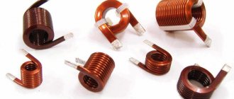
In general, their calculation is a complex process, but for radio amateurs, the calculation given in this book is quite suitable. Electromagnets are used in many electrical devices. It is a coil of wire wound on an iron core, the shape of which can be different. The iron core is one part of the magnetic circuit, and the other part, with the help of which the path of the magnetic lines of force is closed, is the armature. The magnetic circuit is characterized by the magnitude of magnetic induction - B, which depends on the field strength and magnetic permeability of the material. That is why the cores of electromagnets are made of iron, which has high magnetic permeability. In turn, the power flux, denoted in formulas by the letter F, depends on the magnetic induction. F = B • S - magnetic induction - B multiplied by the cross-sectional area of the magnetic circuit - S. The power flow also depends on the so-called magnetomotive force (Em), which is determined by the number of ampere turns per 1 cm of the path length of the power lines and can be expressed by the formula: Ф = magnetomotive force (Em) • magnetic resistance (Rm) Here Em = 1.3•I•N, where N is the number of turns of the coil, and I is the force current flowing through the coil in amperes. Another component: Rm = L/M•S, where L is the average path length of the magnetic power lines, M is the magnetic permeability, and S is the cross-section of the magnetic circuit. When designing electromagnets, it is highly desirable to obtain a large power flux. This can be achieved by reducing the magnetic resistance. To do this, you need to select a magnetic core with the shortest path length of the power lines and the largest cross-section, and the material should be an iron material with high magnetic permeability. Another way of increasing the power flow by increasing the ampere turns is not acceptable, since in order to save wire and power, one should strive to reduce the ampere turns. Usually, calculations of electromagnets are made according to special schedules. To simplify the calculations, we will also use some conclusions from the graphs. Suppose you need to determine the ampere turns and power flux of a closed iron magnetic circuit, shown in Figure 1a and made of the lowest quality iron.
Looking at the graph (unfortunately, I didn’t find it in the appendix) of the magnetization of iron, it is easy to see that the most advantageous magnetic induction is in the range from 10,000 to 14,000 lines of force per 1 cm2, which corresponds to from 2 to 7 ampere turns per 1 cm. For winding coils with the smallest number of turns and more economical in terms of power supply, for calculations it is necessary to take exactly this value (10,000 power lines per 1 cm2 at 2 ampere turns per 1 cm of length). In this case, the calculation can be made as follows. So, with the length of the magnetic circuit L = L1 + L2 equal to 20 cm + 10 cm = 30 cm, 2 × 30 = 60 ampere turns will be required. If we take the diameter D of the core (Fig. 1, c) equal to 2 cm, then its area will be equal to: S = 3.14xD2/4 = 3.14 cm2. Here the excited magnetic flux will be equal to: Ф = B x S = 10000 x 3.14 = 31400 lines of force. The lifting force of the electromagnet (P) can also be approximately calculated. P = B2 • S/25 • 1000000 = 12.4 kg. For a two-pole magnet this result should be doubled. Therefore, P = 24.8 kg = 25 kg. When determining the lifting force, it must be remembered that it depends not only on the length of the magnetic circuit, but also on the area of contact between the armature and the core. Therefore, the armature must fit exactly against the pole pieces, otherwise even the slightest air gaps will cause a strong reduction in lift. Next, the electromagnet coil is calculated. In our example, a lifting force of 25 kg is provided by 60 ampere turns. Let us consider by what means the product N•J = 60 ampere turns can be obtained. Obviously, this can be achieved either by using a high current with a small number of coil turns, for example 2 A and 30 turns, or by increasing the number of coil turns while reducing the current, for example 0.25 A and 240 turns. Thus, in order for the electromagnet to have a lifting force of 25 kg, 30 turns and 240 turns can be wound on its core, but at the same time change the value of the supply current. Of course, you can choose a different ratio. However, changing the current value within large limits is not always possible, since it will necessarily require changing the diameter of the wire used. Thus, during short-term operation (several minutes) for wires with a diameter of up to 1 mm, the permissible current density, at which the wire does not overheat, can be taken equal to 5 a/mm2. In our example, the wire should have the following cross-section: for a current of 2 a - 0.4 mm2, and for a current of 0.25 a - 0.05 mm2, the wire diameter will be 0.7 mm or 0.2 mm, respectively. Which of these wires should be wound? On the one hand, the choice of wire diameter can be determined by the available assortment of wire, on the other hand, by the capabilities of the power sources, both in current and voltage. Indeed, two coils, one of which is made of thick wire of 0.7 mm and with a small number of turns - 30, and the other of which is made of wire of 0.2 mm and a number of turns of 240, will have sharply different resistance. Knowing the diameter of the wire and its length, you can easily determine the resistance. The length of the wire L is equal to the product of the total number of turns and the length of one of them (average): L = N x L1 where L1 is the length of one turn, equal to 3.14 x D. In our example, D = 2 cm, and L1 = 6, 3 cm. Therefore, for the first coil the length of the wire will be 30 x 6.3 = 190 cm, the winding resistance to direct current will be approximately equal to? 0.1 Ohm, and for the second - 240 x 6.3 = 1,512 cm, R? 8.7 Ohm. Using Ohm's law, it is easy to calculate the required voltage. So, to create a current of 2A in the windings, the required voltage is 0.2V, and for a current of 0.25A - 2.2V. This is the elementary calculation of electromagnets. When designing electromagnets, it is necessary not only to make the indicated calculations, but also to be able to choose the material for the core, its shape, and think through the manufacturing technology. Satisfactory materials for making mug cores are bar iron (round and strip) and various. iron products: bolts, wire, nails, screws, etc. To avoid large losses on Foucault currents, cores for alternating current devices must be assembled from thin sheets of iron or wire isolated from each other. To make iron “soft,” it must be annealed. The correct choice of core shape is also of great importance. The most rational of them are ring and U-shaped. Some of the common cores are shown in Figure 1.
Views:40 340
Tags: Electromagnet
Electromagnets are used in many electrical devices. It is a coil of wire wound on an iron core, the shape of which can be different. The iron core is one part of the magnetic circuit, and the other part, with the help of which the path of the magnetic lines of force is closed, is the armature. A magnetic circuit is characterized by the magnitude of magnetic induction - V
, which depends on the field strength and magnetic permeability of the material.
That is why the cores of electromagnets are made of iron, which has high magnetic permeability. When designing electromagnets, it is highly desirable to obtain a large power flux. This can be achieved by reducing the magnetic resistance. To do this, you need to select a magnetic core with the shortest path length of the power lines and the largest cross-section, and the material should be an iron material with high magnetic permeability. Another way of increasing the power flow by increasing the ampere turns is not acceptable, since in order to save wire and power, one should strive to reduce the ampere turns. Usually, calculations of electromagnets are made according to special schedules. To simplify the calculations, we will also use some conclusions from the graphs. Suppose it is necessary to determine the ampere-turns and power flux of a closed iron magnetic circuit, shown in Figure 4a and made of iron of the lowest quality. Considering the graph of iron magnetization, it is easy to see that the most advantageous is magnetic induction in the range from 10,000
to
14,000
lines of force per 1 cm2, which corresponds to from
2
to
7
ampere turns per 1 cm. For winding coils with the least number of turns and more economical in In terms of power supply, for calculations it is necessary to take exactly this value (
10,000
power lines per 1 cm2 at 2 ampere turns per 1 cm of length).
In this case, the calculation can be made as follows. So, with a magnetic circuit length Z=/1-)-/2
equal to
20 cm -f- 10 cm = 30 cm
,
2×30=60
ampere turns will be required.
For a two-pole magnet, this result should be doubled. Therefore, P = 24.8 kg ^ 25 kg
.
When determining the lifting force, it must be remembered that it depends not only on the length of the magnetic circuit, but also on the area of contact between the armature and the core. Therefore, the armature must fit exactly against the pole pieces, otherwise even the slightest air gaps will cause a strong reduction in lift. Next, the electromagnet coil is calculated. In our example, a lifting force of 25 kg
is provided by
60
ampere turns.
Let us consider by what means the product N-J—60
ampere turns can be obtained.
Obviously, this can be achieved either by using a large current with a small number of coil turns, for example 2 A and 30 turns, or by increasing the number of coil turns while reducing the current, for example 0.25 A and 240 turns. Thus, in order for an electromagnet to have a lifting force of 25 kg, both 30 turns and 240 turns can be wound on its core, but at the same time the value of the supply current can be changed. Of course, you can choose a different ratio. However, changing the current value within large limits is not always possible, since it will necessarily require changing the diameter of the wire used. Thus, during short-term operation (several minutes) for wires with a diameter of up to 1. mm, the permissible current density, at which the wire does not overheat, can be taken equal to 5 A/mm2
.
In our example, the wire should have the following cross-section: for a current of 2A - 0.4 mm2
, and for a current of
0.25A - 0.05 mm2
.
Which of these wires should be wound? On the one hand, the choice of wire diameter can be determined by the assortment of wire available to the manager, on the other hand, by the capabilities of the power sources in both current and voltage. Indeed, two coils, one of which is made of thick wire of 0.7 mm and with a small number of turns - 30, and the other of which is made of wire of 0.2 mm and a number of turns of 240, will have sharply different resistance. Knowing the diameter of the wire and its length, you can easily determine the resistance. The length of the wire is equal to the product of the total number of turns and the length of one of them (average): l=Nxlt
where
lt
is the length of one turn, equal to
3.14 x
L. In our example, D = 2 cm, and 1g x 6.3 cm. Therefore, for the first coil, the wire length will be 30 x 6.3 = 190 cm, and for the second - 240 X 6.3 = 1,512 cm. The winding resistances will be also different. Using Ohm's law, it is easy to calculate the required voltage. So, to create a current of 2A in the windings, the required voltage is 0.2V, and for a current of 0.25A - 2.5V. Thus, to power the first coil, one element or battery is enough, and to reduce the voltage you have to turn on the rheostat; To power the second coil, you need to take two elements, connecting them in series. It is clear that in the second case there are fewer losses of electricity and the winding turns out to be more profitable. Analysis of the results obtained allows us to draw the following conclusion: the diameter of the wire is selected so that the coil can be powered from only one element (or battery) without any rheostats, where energy is wasted involuntarily. It is easy to see that with a wire diameter of approximately 0.4 mm and a current strength of about 0.4 A, the required voltage to power the coil will be 1.3-1.4 V, that is, exactly the voltage of one element. This is the elementary calculation of electromagnets.
Calculation of AC magnetic circuits
5.6.1. Features of calculating alternating current magnetic circuits.
AC magnetic circuits have the following features. The current in the electromagnet coil depends mainly on the inductive reactance, which, in turn, is determined by the size of the air gap. The magnetic resistance of the circuit depends on losses in the steel and the presence of short-circuited windings located on the magnetic core.
The magnetic core is usually made laminated (in order to reduce losses due to eddy currents) of a rectangular cross-section, which leads to an increase in the average length of the winding turn and copper consumption.
Let us consider the influence of these features on the calculation of an alternating current magnetic circuit.
5.6.2. Taking into account the influence of losses in steel.
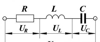
The vector diagram of the magnetic circuit with alternating current has the form shown in Fig.
62 and is similar to the vector diagram of a transformer in no-load mode. In the diagram, the MMF vector of the kA carcass (Iw)
is shifted relative to the vector
current fm
to the corner. The MMF of the coil can be decomposed into two components:
(Iw)a
– an active component that is in phase with the magnetic flux and is spent on conducting the flux through all sections of the magnetic circuit;
(Iw)r
– reactive component, shift-
Rice. 62. Vector diagram
tue with respect to magnetic flux
at an angle of 90 degrees. The reactive component of the MMF is spent to compensate for the effects of losses in steel from magnetization reversal and eddy currents.
By analogy with electrical circuits, we can write:
– active component of the magnetic resistance of the magnetic circuit;
– reactive component of the magnetic resistance of the magnetic circuit;
– total magnetic resistance.
Thus, the influence of magnetization reversal of the magnetic circuit and the eddy currents arising in it can be taken into account by introducing inductive magnetic reluctances into the equivalent circuit of the magnetic circuit. Consequently, sections of the magnetic circuit of the alternating current magnetic circuit are characterized by a total complex magnetic resistance
or . (157)
Magnetic resistance values can be determined as follows:
, (158)
here γ
– steel density;
pst
– specific losses in steel;
V
is the steel volume of the magnetic circuit section;
f
– network frequency;
Bm
– amplitude of magnetic induction;
S
– cross-sectional area of the steel section of the m.c.;
Фm
is the amplitude of the magnetic flux.
, (159)
here Um
– magnetic voltage in the considered area of the m.c.;
l
is the average length of the magnetic line in the area of the m.c.;
Hm
– magnetic field strength in the area of the m.c.; – magnetic permeability of steel in the m.c. area.
Hm values
,
Bm
and are determined from the magnetization curve taken with alternating current. Then, the active resistance of the magnetic circuit will be equal to
. (160)
Sections of the magnetic circuit in the form of air gaps create only active magnetic resistance, since in these sections there are no losses due to magnetization reversal and eddy currents
. (161)
5.6.3. Taking into account the influence of a short-circuited winding.
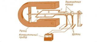
Let us consider the influence of a short-circuited winding using the example of a U-shaped alternating current electromagnet, with a short-circuited winding covering the entire cross-section of the core (Fig. 63).
We neglect scattering fluxes. Let us compose the MDS equilibrium equation according to Kirchhoff’s second law in complex form
, (162)
Where
r2
and
x2
– active and inductive resistance of the short-circuited winding.
EMF induced in the short circuit winding
Rice. 63. Electromagnet
. (163)
alternating current
Let us substitute (165) into
I2
and make the transformation
nia
. (164)
I2 value
Let us substitute (164) into the equilibrium equation and solve for
I1w1
. (165)
Let us introduce the notation
; . (166)
Thus, the short-circuited winding is taken into account when calculating the magnetic circuit using two magnetic resistances –
active
Rm2
and inductive
Xm2
. Then the equation of a magnetic circuit with a short-circuited winding is described by Ohm’s law
. (167)
In alternating current magnetic circuits, the short-circuited winding is made in the form of one turn - a screen covering part of the pole in the air gap. The screen serves to reduce armature vibration. In this regard, the inductive reactance of the screen is low ( x2 << r2
), So
like w2
= 1 and can be neglected (
x2
= 0). Then,
Rм2
= 0 . (168)
In the equivalent circuit, the screen is taken into account by introducing inductive reactance Xe
.
5.6.4. Dependence of current and flux on the air gap.
Let's consider the simplest magnetic circuit of alternating current (Fig. 63) without taking into account the resistance of steel (
Rmst = 0
), losses in it (
Pst = 0
), leakage fluxes () and short-circuited screens (
Xe = 0
).
The mains voltage applied to the coil is balanced by the active and reactive voltage drop
, (169) where U
and
I
are taken in actual values.
. (170)
It follows that the inductive reactance of the winding will be equal to
, (171)
i.e., it is inversely proportional to the air gap.
For a shunt winding, i.e. a winding connected parallel to the terminals of the power source, the active resistance is significantly less than the reactive one ( R
<< ).
Therefore, as a first approximation, we can neglect active resistance ( R
= 0) and then
U = IX
. (172)
But since , then we get – the amplitude value of the flow.
Thus, under the assumptions made ( R
= 0 and
Pst
= 0), the flux associated with the coil does not depend on the working gap and is a constant value, and when
U = IX
it follows
, (173)
that is, as the air gap increases, the inductive resistance of the winding decreases, and the current in it increases.
However, the accepted assumption is valid only in a limited range of changes in air gaps. Thus, from the graphs (Fig. 64) it is clear that in the gap range the active resistance R
commensurate with inductive reactance
X
and even
Rice. 64. Dependencies
more of him. Therefore, taking into account the active resistance
R and X from δ
of the winding, the magnetic flux will be equal to
, (174)
As the working air gap increases, the current in the winding increases, and the flux in the magnetic circuit will fall in the same way as in a direct current magnetic circuit. But in a direct current magnetic circuit, a decrease in flux occurs as a result of an increase in the magnetic resistance of the air gap, and in an alternating current magnetic circuit also as a result of an increase in the voltage drop across the active resistance of the winding. If we take into account the leakage flux Фs
, then as the gap increases, the current in the winding will increase disproportionately, as is
Rice. 65. To the calculation of the magnetic circuit
follows from formula (173), which means
alternating current
definitely slower.
Thus, active resistance and magnetic leakage flux restrain the growth of current in the electromagnet coil.
5.6.1. Features of calculating alternating current magnetic circuits.
AC magnetic circuits have the following features. The current in the electromagnet coil depends mainly on the inductive reactance, which, in turn, is determined by the size of the air gap. The magnetic resistance of the circuit depends on losses in the steel and the presence of short-circuited windings located on the magnetic core.
The magnetic core is usually made laminated (in order to reduce losses due to eddy currents) of a rectangular cross-section, which leads to an increase in the average length of the winding turn and copper consumption.
Let us consider the influence of these features on the calculation of an alternating current magnetic circuit.
5.6.2. Taking into account the influence of losses in steel.
The vector diagram of the magnetic circuit with alternating current has the form shown in Fig.
62 and is similar to the vector diagram of a transformer in no-load mode. In the diagram, the MMF vector of the kA carcass (Iw)
is shifted relative to the vector
current fm
to the corner. The MMF of the coil can be decomposed into two components:
(Iw)a
– an active component that is in phase with the magnetic flux and is spent on conducting the flux through all sections of the magnetic circuit;
(Iw)r
– reactive component, shift-
Rice. 62. Vector diagram
tue with respect to magnetic flux
at an angle of 90 degrees. The reactive component of the MMF is spent to compensate for the effects of losses in steel from magnetization reversal and eddy currents.
By analogy with electrical circuits, we can write:
– active component of the magnetic resistance of the magnetic circuit;
– reactive component of the magnetic resistance of the magnetic circuit;
– total magnetic resistance.
Thus, the influence of magnetization reversal of the magnetic circuit and the eddy currents arising in it can be taken into account by introducing inductive magnetic reluctances into the equivalent circuit of the magnetic circuit. Consequently, sections of the magnetic circuit of the alternating current magnetic circuit are characterized by a total complex magnetic resistance
or . (157)
Magnetic resistance values can be determined as follows:
, (158)
here γ
– steel density;
pst
– specific losses in steel;
V
is the steel volume of the magnetic circuit section;
f
– network frequency;
Bm
– amplitude of magnetic induction;
S
– cross-sectional area of the steel section of the m.c.;
Фm
is the amplitude of the magnetic flux.
, (159)
here Um
– magnetic voltage in the considered area of the m.c.;
l
is the average length of the magnetic line in the area of the m.c.;
Hm
– magnetic field strength in the area of the m.c.; – magnetic permeability of steel in the m.c. area.
Hm values
,
Bm
and are determined from the magnetization curve taken with alternating current. Then, the active resistance of the magnetic circuit will be equal to
. (160)
Sections of the magnetic circuit in the form of air gaps create only active magnetic resistance, since in these sections there are no losses due to magnetization reversal and eddy currents
. (161)
5.6.3. Taking into account the influence of a short-circuited winding.
Let us consider the influence of a short-circuited winding using the example of a U-shaped alternating current electromagnet, with a short-circuited winding covering the entire cross-section of the core (Fig. 63).
We neglect scattering fluxes. Let us compose the MDS equilibrium equation according to Kirchhoff’s second law in complex form
, (162)
Where
r2
and
x2
– active and inductive resistance of the short-circuited winding.
EMF induced in the short circuit winding
Rice. 63. Electromagnet
. (163)
alternating current
Let us substitute (165) into
I2
and make the transformation
nia
. (164)
I2 value
Let us substitute (164) into the equilibrium equation and solve for
I1w1
. (165)
Let us introduce the notation
; . (166)
Thus, the short-circuited winding is taken into account when calculating the magnetic circuit using two magnetic resistances –
active
Rm2
and inductive
Xm2
. Then the equation of a magnetic circuit with a short-circuited winding is described by Ohm’s law
. (167)
In alternating current magnetic circuits, the short-circuited winding is made in the form of one turn - a screen covering part of the pole in the air gap. The screen serves to reduce armature vibration. In this regard, the inductive reactance of the screen is low ( x2 << r2
), So
like w2
= 1 and can be neglected (
x2
= 0). Then,
Rм2
= 0 . (168)
In the equivalent circuit, the screen is taken into account by introducing inductive reactance Xe
.
5.6.4. Dependence of current and flux on the air gap.
Let's consider the simplest magnetic circuit of alternating current (Fig. 63) without taking into account the resistance of steel (
Rmst = 0
), losses in it (
Pst = 0
), leakage fluxes () and short-circuited screens (
Xe = 0
).
The mains voltage applied to the coil is balanced by the active and reactive voltage drop
, (169) where U
and
I
are taken in actual values.
. (170)
It follows that the inductive reactance of the winding will be equal to
, (171)
i.e., it is inversely proportional to the air gap.
For a shunt winding, i.e. a winding connected parallel to the terminals of the power source, the active resistance is significantly less than the reactive one ( R
<< ).
Therefore, as a first approximation, we can neglect active resistance ( R
= 0) and then
U = IX
. (172)
But since , then we get – the amplitude value of the flow.
Thus, under the assumptions made ( R
= 0 and
Pst
= 0), the flux associated with the coil does not depend on the working gap and is a constant value, and when
U = IX
it follows
, (173)
that is, as the air gap increases, the inductive resistance of the winding decreases, and the current in it increases.
However, the accepted assumption is valid only in a limited range of changes in air gaps. Thus, from the graphs (Fig. 64) it is clear that in the gap range the active resistance R
commensurate with inductive reactance
X
and even
Rice. 64. Dependencies
more of him. Therefore, taking into account the active resistance
R and X from δ
of the winding, the magnetic flux will be equal to
, (174)
As the working air gap increases, the current in the winding increases, and the flux in the magnetic circuit will fall in the same way as in a direct current magnetic circuit. But in a direct current magnetic circuit, a decrease in flux occurs as a result of an increase in the magnetic resistance of the air gap, and in an alternating current magnetic circuit also as a result of an increase in the voltage drop across the active resistance of the winding. If we take into account the leakage flux Фs
, then as the gap increases, the current in the winding will increase disproportionately, as is
Rice. 65. To the calculation of the magnetic circuit
follows from formula (173), which means
alternating current
definitely slower.
Thus, active resistance and magnetic leakage flux restrain the growth of current in the electromagnet coil.
Login to the site
Electromagnets are used in many electrical devices. It is a coil of wire wound on an iron core, the shape of which can be different.The iron core is one part of the magnetic circuit, and the other part, with the help of which the path of the magnetic lines of force is closed, is the armature.
The magnetic circuit is characterized by the magnitude of magnetic induction - B, which depends on the field strength and magnetic permeability of the material. That is why the cores of electromagnets are made of iron, which has high magnetic permeability.
In turn, the power flux, denoted in formulas by the letter F, depends on magnetic induction.
Ф = B x S = magnetic induction x cross-sectional area of the magnetic circuit.
When designing electromagnets, it is highly desirable to obtain a large power flux. This can be achieved by reducing the magnetic resistance. To do this, you need to select a magnetic core with the shortest path length of the power lines and the largest cross-section, and the material should be an iron material with high magnetic permeability.
Another way of increasing the power flow by increasing the ampere turns is not acceptable, since in order to save wire and power, one should strive to reduce the ampere turns.
Usually, calculations of electromagnets are made according to special schedules. To simplify the calculations, we will also use some conclusions from the graphs. Suppose you need to determine the ampere turns and power flux of the closed iron magnetic circuit shown in the figure and made of iron of the lowest quality.
Considering the graph of iron magnetization, it is easy to see that the most advantageous is magnetic induction in the range from 10,000 to 14,000 lines of force per 1 cm2, which corresponds to from 2 to 7 ampere turns per 1 cm. For winding coils with the least number of turns and more economical in In terms of power supply, for calculations it is necessary to take exactly this value (10,000 power lines per 1 cm2 at 2 ampere turns per 1 cm of length). In this case, the calculation can be made as follows. So, with a magnetic circuit length l = l1 + l2 equal to 20 cm + 10 cm = 30 cm, 2 × 30 = 60 ampere turns will be required.
If we take the core diameter to be 2 cm, then its area will be S = (3.14 x d2) / 4 = 3.14 cm2. Hence the excited magnetic flux will be equal to: Ф = B x S = 10000 x 3.14 = 31400 lines of force.
The lifting force of the electromagnet (P) can be approximately calculated.
P = B2x S / (25 x 1000000) = 12.4 kg.
For a two-pole magnet, this result should be doubled. Therefore, P=24.8 kg, or approximately 25 kg.
When determining the lifting force, it must be remembered that it depends not only on the length of the magnetic circuit, but also on the area of contact between the armature and the core. Therefore, the armature must fit exactly against the pole pieces, otherwise even the slightest air gaps will cause a strong reduction in lift.
Next, the electromagnet coil is calculated. In our example, a lifting force of 25 kg is provided by 60 ampere turns. Let us consider by what means we can obtain the product N x J - 60 ampere turns.
Obviously, this can be achieved either by using a large current with a small number of coil turns, for example 2 A and 30 turns, or by increasing the number of coil turns while reducing the current, for example 0.25 A and 240 turns.
Thus, in order for the electromagnet to have a lifting force of 25 kg, 30 turns and 240 turns can be wound on its core, but at the same time change the value of the supply current. Of course, you can choose a different ratio.
However, changing the current value within large limits is not always possible, since it will necessarily require changing the diameter of the wire used. Thus, during short-term operation (several minutes) for wires with a diameter of up to 1 mm, the permissible current density, at which the wire does not overheat, can be taken equal to 5 A/mm2. In our example, the wire should have the following cross-section: for a current of 2A - 0.4 mm2, and for a current of 0.25A - 0.05 mm2.
Which of these wires should be wound?
On the one hand, the choice of wire diameter can be determined by the assortment of wire available to the manager, on the other hand, by the capabilities of the power sources in both current and voltage. Indeed, two coils, one of which is made of thick wire of 0.7 mm and with a small number of turns - 30, and the other of which is made of wire of 0.2 mm and a number of turns of 240, will have sharply different resistance.
Knowing the diameter of the wire and its length, you can easily determine the resistance. The length of the wire is equal to the product of the total number of turns and the length of one of them (average): l=N x lt where lt is the length of one turn, equal to 3.14 x d.
In our example, d = 2 cm, and lt 6.3 cm. Therefore, for the first coil the length of the wire will be 30 x 6.3 = 190 cm, and for the second - 240 X 6.3 = 1512 cm. The resistances of the windings will also be different .
Using Ohm's law, it is easy to calculate the required voltage. So, to create a current of 2A in the windings, the required voltage is 0.2V, and for a current of 0.25A - 2.5V.
Thus, to power the first coil, one element or battery is enough, and to reduce the voltage you have to turn on the rheostat. To power the second coil, you need to take two elements, connecting them in series. It is clear that in the second case there are fewer losses of electricity and the winding turns out to be more profitable.
Analysis of the results obtained allows us to draw the following conclusion: the diameter of the wire is selected so that the coil can be powered from only one element (or battery) without any rheostats, where energy is wasted involuntarily. It is easy to see that with a wire diameter of approximately 0.4 mm and a current strength of about 0.4 A, the required voltage to power the coil will be 1.3 - 1.4 V, that is, exactly the voltage of one element.
This is the elementary calculation of electromagnets.
Source: Technical Creativity. Publishing house of the Komsomol Central Committee “Young Guard”. M., 1955
You can download the book itself in DjVu format from this link: https://narod.ru/disk/21046539000/creation.zip.html (30 MB)