Inductance and its calculation:
The basic relationship for the magnetic field is the principle of magnetic flux continuity:
In Fig. 1.12, a and b illustrate the difference between flow and flux linkage, and the number of lines on a conventional scale is equal to the magnitude of the flow.
Induction is measured in teslas (tl), magnetic flux and flux linkage are measured in webers (wb). Inductance of a solitary circuit, equal to the ratio of flux linkage to current:
is proportional to the magnetic permeability of the medium in which it is located and is determined by the configuration of the circuit. The unit of inductance is henry (hn). To calculate the inductance of a circuit, it is necessary to first calculate its magnetic field according to the basic relationship - the law of total current:
establishing a connection between the magnetic field strength and the total current I - the algebraic sum of currents coupled with the path of integration. In this case, the positive direction of the current I is related to the direction dI of the bypass by the rule of the right screw. Magnetic field strength is measured in a/m, magnetic permeability in Hz/m. If the flux linkage of the circuit changes over time, then e appears in the circuit. d.s. induction e, the magnitude and direction of which is determined by the law of electromagnetic induction:
where E is the intensity vector of the electric field induced in the circuit. Thus, the law of electromagnetic induction relates the change in the magnetic field with the resulting electric field. Maxwell postulated a generalization of this law, which consists in the fact that an electric field arises when a magnetic field changes in any medium, and not just in a conducting circuit.
The law of electromagnetic induction, discovered by Faraday in 1831, was supplemented by Lenz in 1832-1834. They established a general rule: h. d.s. Induction always strives to create a current directed so as to prevent a change in the flux adhering to the circuit. When the current in the circuit changes, the flux linkage ψL created by this current changes, and e is induced in the circuit. d.s. self-induction
Toroid and Solenoid Inductance
If a winding is applied to a ring core—a toroid made of a material with permeability µ > µ0—not along its entire length (Fig. 1.13), then only part of the flux passes through the core, the rest—the leakage flux—is closed in the air. The toroid, which contains turns densely and evenly distributed along the entire length of the core (Fig. 1.14), is remarkable in that almost the entire magnetic flux is concentrated in the core, i.e., there is no leakage flux. The field strength vector lines are circles interlocking with all turns. Due to symmetry, the field strength at each point of the circle is constant in magnitude; in direction it coincides with the tangent to the circle.
Toroids are widely used in transformers, magnetic amplifiers and electrical measuring instruments.
Let the toroid have a rectangular cross-section with a height H, with radii r1 and r2, and the magnetic permeability of the material µ.
According to the law of total current for a circle with radius
where
that is, the field strength decreases as it approaches the outer edge of the toroid. This applies equally to induction
Flux in the toroid core
and flux linkage
Hence the inductance of the toroid
If the calculation is carried out for the center line I and the field in the toroid is approximately assumed to be uniformly distributed, then the intensity
where w0 is the number of turns per unit length, and the magnetic flux and inductance, respectively,
Typically, in real toroids, the ratio that leads with these approximate formulas to an error not exceeding 1.2%. The last formula for inductance can also be applied to a long solenoid, considered as part of a toroid of infinitely large radius. For a solenoid of finite length µ=µ0
where k
As an accurate calculation shows, this coefficient depends on the ratio of the diameter D of the coil to its length I (Fig. 1.15). At = 0.1 the coefficient k is 0.96, therefore at
Application in technology
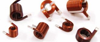
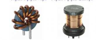
Inductors are used:
Rice. 9. Inductors
- For noise suppression, ripple smoothing, energy storage, alternating current limitation, in resonant (oscillating circuit) and frequency-selective circuits; creating magnetic fields, motion sensors, in credit card readers, as well as in contactless credit cards themselves.
- Inductors (together with capacitors and resistors) are used to construct various circuits with frequency-dependent properties, in particular filters, feedback circuits, oscillating circuits and others. Such coils, accordingly, are called: contour coil, filter coil, and so on.
- Two inductively coupled coils form a transformer.
- An inductor, powered by a pulsed current from a transistor switch, is sometimes used as a high-voltage source of low power in low-current circuits when creating a separate high supply voltage in the power supply is impossible or economically impractical. In this case, high voltage surges appear on the coil due to self-induction, which can be used in the circuit.
- When used to suppress interference, smooth out electrical current ripples, isolate (high-frequency) different parts of the circuit, and store energy in the magnetic field of the core, an inductor is called an inductor.
- In power electrical engineering (to limit the current during, for example, a short circuit of a power line), an inductor is called a reactor.
- Current limiters for welding machines are made in the form of an inductance coil, limiting the current of the welding arc and making it more stable, thereby allowing for a more even and durable weld.
- Inductors are also used as electromagnets - actuators. A cylindrical inductor whose length is much greater than its diameter is called a solenoid. In addition, a solenoid is often called a device that performs mechanical work due to a magnetic field when a ferromagnetic core is retracted.
- In electromagnetic relays, the inductors are called relay windings.
- A heating inductor is a special inductor coil, the working element of induction heating installations and kitchen induction ovens.
By and large, in all electric current generators of any type, as well as in electric motors, their windings are inductor coils. Following the ancient tradition of depicting a flat Earth standing on three elephants or whales, today we could with greater justification assert that life on Earth rests on an inductive coil.
Rice. 15. Earth's magnetosphere
After all, even the Earth’s magnetic field, which protects all terrestrial organisms from corpuscular cosmic and solar radiation, according to the main hypothesis about its origin, is associated with the flow of huge currents in the liquid metal core of the Earth. In essence, this core is a planetary-scale inductor. It is calculated that the zone in which the “magnetic dynamo” mechanism operates is located at a distance of 0.25-0.3 Earth radii.
Rice. 7. Magnetic field around a current-carrying conductor. I
— current,
B
— magnetic induction vector.
Two-wire line inductance
A two-wire line (Fig. 1.16, a) consists of two parallel wires of the same radius r0, having a greater length I compared to the distance d between them. Magnetic permeability of the wire material (g, environment) is µ0. The currents I in the forward and return wires differ only in direction; the origin of coordinates is taken at the center of the cross section of the left wire.
For an individual wire, due to its axial symmetry, neglecting the field distortion at its ends, applying the total current law to a circle of radius gives:
When integrating over a circle lying inside a separate wire, only part LX of the total current flowing inside a circle of radius x is covered, equal to when the current is uniformly distributed over the cross section
In the air between the wires on the line connecting the centers of their sections, the directions of the fields created by both currents according to the right screw rule coincide and the field strengths and induction add up:
The same formulas are also valid for i.e. outside the line, but here they give the field difference.
Inside the left wire of the line, the field strength and induction from both wires will be:
Inside the right wire, respectively,
In Fig. Figure 1.16b shows the distribution of field strength and induction along the x axis for the magnetic permeability of the wire material µ > µ0. In the middle between the wires the field is minimal, but does not go to zero. The field is also not zero on the wire axes.
On the inside of the wires, the field strength and induction are greater than on the outside. Unlike field strength, induction has a discontinuity at the surface of the wires. To calculate the line inductance, it is necessary to find the flux linkage. The elementary flux passing through the Idx pad in the air between the wires is
All flow between wires is external flow
at the same time it is an external flux linkage, since it couples with the circuit once. That's why
and the corresponding external inductance
For most lines, the distance d between the wires significantly exceeds the radius r0 of the wires. In this case
To determine the internal inductance corresponding to the internal flux, for d > r0, the field inside the line wire can be calculated as the field of an isolated wire, since the field created by the second wire inside the first, compared to the field of the first, is negligible. Then the elementary flux inside the wire
Since the flow dФi does not cover the entire current, but only part of it [see. formula (1.3)], elementary flux linkage
All flow between wires is external flow
Accordingly, the internal inductance
Total line inductance
With copper or aluminum wires () in most cases the second term can be neglected compared to the first and then
For steel wires (), the main part of the flux is internal flux and inductance
will practically not depend on the distance between the wires.
Hydraulic model
The operation of an inductor can be compared to the operation of a hydraulic turbine in a flow of water. The flow of water directed through a turbine that has not yet been spun up will feel resistance until the turbine is completely spun up.
Next, the turbine, which has a certain degree of inertia, rotates in a uniform flow, practically without affecting the speed of water flow. If this flow is suddenly stopped, the turbine will still rotate by inertia, creating water movement. And the higher the inertia of a given turbine, the more it will resist changes in flow.
Soldering iron YIHUA 8858
Updated version, power: 600 W, air flow: 240 l/h...
More details
Also, an inductive coil resists changes in the electric current flowing through it.
Mutual inductance and its calculation
For two circuits having w1 and w2 turns with currents I1 and I2 (Fig. 1.17), the flux of the first circuit, determined by the current of this circuit, the self-induction flux Ф1l, can be decomposed into the leakage flux Ф1s, penetrating only this circuit, and the mutual induction flux Ф1m, also penetrating the second circuit:
The flux linkage corresponding to flow F11 (provided that this flow penetrates all turns of the primary circuit is equal to
and leakage flux linkage
Similarly for the second circuit
The flux linkage of the second circuit, determined by the current of the first,
and the flux linkage of the first circuit, determined by the current of the second,
It can be shown that
The value M is called mutual inductance and is determined by the configuration of the circuits, their relative position and the magnetic permeability of the medium. Mutual inductance is also measured in henry (H). The total flow passing through the first circuit is
Total primary circuit flux linkage
and accordingly for the second circuit
In these algebraic sums, the first term is always positive, and the sign before the second term is determined by the direction of the currents in the circuits; a positive sign corresponds to the case when the directions of flows Ф1м and Ф2м coincide (see Fig. 1.17). From the above it is clear that
Thus, mutual inductance and inductances always satisfy the inequality
and the coupling coefficient of two circuits used in technical calculations
Similarly, in a system of many loops, the flux linkage of the loop is determined by the currents of all loops:
where Lq is the inductance of the qth circuit, Mqp = Мрq is the mutual inductance of the qth and pth circuits. The general technique for calculating the mutual inductance of circuits is to find the flux linkage that penetrates the circuit q, but created by the current of the pth circuit, and divide it by this current.
Mutual inductance of two parallel two-wire lines
Let two parallel two-wire lines be arranged symmetrically as shown in Fig. 1.4. Under the condition d> r0, the internal flux in the wires can be neglected compared to the external one. The magnetic flux passing through the first line and created by the current I2 of the second can be found as the sum of the fluxes created by each of the wires of the second line separately. Then the magnetic flux penetrating the first line
distances from the wire of line 1 to the wires of line 2.
Magnetic flux Ф is at the same time the flux linkage of the first line, since it couples with it once; That's why
and mutual inductance
To reduce the coupling coefficient between communication lines l and transmission 2, a transposition of the communication line is used, which consists in crossing the wires of the communication line at equal distances; then the total flux linkage will be zero.
Linear and nonlinear inductors
For linear materials, the magnetic permeability µ does not depend on the field strength and the characteristic for them is depicted by a straight line (Fig. 1.18, a). Magnetic permeability is proportional to the tangent of the angle a of the slope of this straight line:
where k is the scale factor.
Nonlinear materials include ferromagnets and iron, nickel, cobalt and gadolinium. The first three elements are important in electrical engineering, mainly in the form of alloys. In nonlinear materials, the magnetic permeability is very high and depends on the field strength.
Similar to nonlinear dielectrics, the static magnetic permeability can be determined from the initial magnetization curve B (H) (Fig. 1.18, b)
and differential, and with rapid field changes - dynamic magnetic permeability
In Fig. 1.18, b these permeabilities are presented as a function of field strength. The maximum values of magnetic permeability in very pure iron and in some alloys, for example in permalloy (an alloy of iron and nickel with various additives), are hundreds of thousands of times higher than the magnetic constant equal to
magnetic permeability of vacuum.
In alternating magnetic fields in ferromagnets, the phenomenon of magnetic hysteresis occurs (Fig. 1.19), which consists in the discrepancy between the B (H) curve as the field strength increases and the curve as the field decreases.
The curve connecting the tops of the hysteresis loops is called the main magnetization curve and practically coincides with the initial magnetization curve. Ferromagnetic properties depend on temperature and appear only in a certain temperature range.
To calculate the inductance, the main one is the dependence of the flux linkage ψ on the current I, called the Weber-ampere characteristic.
Depending on the core material, the toroids will also be linear or nonlinear in terms of their weberampere characteristics. A nonlinear toroid is considered as an example.
For a toroid, the webampere characteristics ψ (I) on the appropriate scale coincide with curves B (H); therefore the straight line and curves in Fig. 1.18 a and b also correspond to weberampere characteristics at the values indicated in parentheses.
For nonlinear toroids, the concepts of static inductance are introduced
and differential as well as dynamic inductance
which are functions of current (see Fig. 1.18, b); for linear toroids these inductances are the same.
Similar to inductances in nonlinear circuit systems, static mutual inductance is introduced
and differential, mutual inductance, as well as dynamic
Inductance in electrical circuits
While a capacitor resists changes in alternating voltage, inductance resists alternating current. An ideal inductance will have no resistance to direct current, however, in reality, all inductive coils themselves have a certain resistance.
In general, the relationship between the time-varying voltage V(t) passing through a coil of inductance L and the time-varying current I(t) passing through it can be represented as a differential equation of the following form:
When a sinusoidal alternating current (AC) flows through an inductor, a sinusoidal alternating voltage (EMV) is generated. The amplitude of the EMF depends on the amplitude of the current and the frequency of the sinusoid, which can be expressed by the following equation:
where ω is the angular frequency of the resonant frequency F:
Moreover, the phase of the current lags behind the voltage by 90 degrees. In a capacitor, the opposite is true, where the current leads the voltage by 90 degrees. When an inductive coil is connected to a capacitor (series or parallel), an LC circuit is formed that operates at a specific resonant frequency.
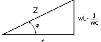
Inductive reactance XL is determined by the formula:
where XL is the inductive reactance, ω is the angular frequency, F is the frequency in hertz, and L is the inductance in henry.
Inductive reactance is the positive component of impedance. It is measured in ohms. The impedance of the inductor (inductive reactance) is calculated by the formula: