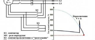
Methods for starting DC motors that reduce the load on motor parts due to increased starting current values. Features of direct start implementation, its advantages and disadvantages. How three-phase electric motors are started by gradually increasing the supply voltage.
A characteristic feature of direct current electric motors (DCM) is the need to use starting currents of increased rating compared to the more common asynchronous electric motors operating on alternating current. This forces manufacturers to more carefully choose the method of starting a DC motor, which will determine the functionality of the electric motor, its reliability and durability.
In practice, several starting methods are used, each of which is capable of temporarily limiting the value of the starting current so that the armature winding circuit does not fail prematurely.
Let's consider the listed methods in more detail.
Direct start
When starting an EPT, the current load increases along with an increase in the value of torque transmitted to the rotor. This moment is characterized by a significant increase in the temperature of the stator winding, which can cause insulation damage and short circuit. A sharp increase in load is fraught with strong vibrations and leads to mechanical damage to motor parts.
With direct starting, the problem is solved by connecting the armature winding directly to the electrical circuit, but subject to the stability of the electric current.
Direct starting of a DC electric motor is used for low-power electric motors (with a rating not exceeding 1 kW), and it is the easiest to implement. In this case, operating temperatures do not increase as much as when using other starting methods.
In case of intensive use of the electric motor with frequent switching on/off, it is equipped with a manually controlled release. Its task is to supply voltage directly to the motor terminals at the moment of starting.
Symbols for DC motors of the P series.
P X1 X2 X3 M P – DC machine; X1 – version according to the degree of protection and cooling method. Without a letter - splash-proof with self-ventilation size 1-6. B – closed version with natural cooling, size 1-4; X2 – dimensions of the electric machine. 1-1 dimensions, 2-2 dimensions, 3-3 dimensions, 4-4 dimensions, 5-5 dimensions, 6-6 dimensions; X3 – nominal length of the armature core. 1 – first length, 2 – second length; M – marine version;
According to the installation method, DC electric motors have a design - IM1001, IM2101, IM2111, IM2131, IM3601, IM3631, IM3611. DC motors can be manufactured with an attached tachogenerator.
Operating conditions for DC electric motors P51, P52.
- DC motors P51, P52 are manufactured for operation at ambient temperatures from -40°C to +40°C.
- At an ambient temperature of 20° ± 5°C% relative humidity 95°±3°C%.
- Withstands vibration, shock, long-term tilting of the axis of a DC electric motor from 45° in any direction and when rolling up to 45° with a rolling period of 7-9 s.
Excitation of a DC motor is serial, parallel, mixed, independent. The heat resistance class of DC electric motor insulation is N. The general level of vibration of electric motors and the level of airborne noise intensity comply with all accepted standards.
Overall and connecting dimensions of DC motors P51, P52, PB51, PB52
| Type of DC motors | Dimensions, mm | Weight, kg for IM2101, IM2102, IM3601, IM2103, IM2104, IM3611, IM3631 | Weight, kg for IM1001, IM1004 | ||||||
| b10 | d1 | d20 | d30 | l10 | l30 | h | |||
| P51U4 | 264 | 35 | 255 | 352 | 225 | 606 | 180 | 122 | 115 |
| PB51U2 | 638 | 127 | 120 | ||||||
| P52U4 | 264 | 35 | 255 | 352 | 265 | 646 | 180 | 142 | 135 |
| PB52U2 | 678 | 147 | 140 |
Main technical characteristics of DC motors P51, P52
| Type | power, kWt | Voltage V | Mains current A | Rotation speed, rpm | Efficiency % |
| P51M | 2,7 | 110 | 33 | 750/1500 | 71 |
| 2,7 | 220 | 17,2 | 750/1500 | 74 | |
| 4,2 | 110 | 52,2 | 1000/2000 | 73 | |
| 4,2 | 220 | 25,6 | 1000/2000 | 74,5 | |
| 7,4 | 110 | 83,6 | 1500/2250 | 79,5 | |
| 7,4 | 220 | 41,8 | 1500/2250 | 80 | |
| 14,5 | 110 | 153 | 3000/3300 | 85 | |
| 14,5 | 220 | 77,3 | 3000/3300 | 85 | |
| P52M | 3,4 | 220 | 20,8 | 750/1500 | 74,5 |
| 5 | 110 | 58,5 | 1000/2000 | 77 | |
| 5 | 220 | 29,2 | 1000/2000 | 77 | |
| 8,8 | 110 | 97,8 | 1500/2250 | 81,5 | |
| 8,8 | 220 | 48 | 1500/2250 | 82,5 | |
| 16 | 220 | 84,5 | 2800 | 86 | |
| 20 | 220 | 104 | 3000/3300 | 87 |
DC electric motors of the P series 1, 2, 3, 4 dimensionsDC electric motors of the P51, P52 seriesDC electric motors of the P61, P62 seriesDC motors of the 2P series (2PO132 - 2PO200, 2PF132 - 2PF200)DC electric motors 2PN, 2PBElectric DC machines of the 4PD series DC motors current DP-112, DK-112, DKU-112MR permanent magnet motors
MTA motors on permanent magnetsPI, PC, 3PI motors on permanent magnetsMX, MVN, MVO motors on permanent magnetsDC electric motors of the DE seriesDC electric motors DPMEDC electric motors DPURDC electric motors PBS, PBSTDC electric motors DK-309M
Rheostat start
This method, unlike the previous one, is used to ensure the start of high-power electric motors.
To do this, a rheostat is included in its electrical circuit, which is a sectional wire with a high resistivity. With the rheostatic method of starting an EPT, the resistance of the rheostat quickly decreases, which eliminates large current drops.
This technique allows the electric motor shaft to accelerate with constant acceleration, which has a positive effect on the durability of the engine. The number of rheostat sections can vary widely, usually 2-7 segments. Their number depends on the difference between the maximum and minimum values of the starting current, as well as on the requirements for smooth starting.
The problem of ensuring equalization of starting current values at all stages of the process within a given time period is solvable, but in general it cannot be automated. If it is impossible without this, that is, the EPT is part of an automated complex; a technique with automatic contactors is used, which operate alternately and bypass the starting resistance.
When the engine reaches operating speed, the rheostat must be disconnected from the circuit, since its characteristics allow it to operate for a short time, otherwise it will simply fail. The decrease in resistance, as well as its increase at the beginning, occurs discretely.
Dynamic braking.
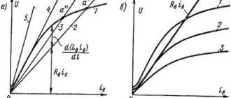
The need for such braking arises in the case when, after disconnecting the engine from the network, its armature continues to rotate under the influence of the kinetic energy of the moving masses of the electric drive. If at the same time the armature winding, disconnected from the network, is shorted to a resistor rt, then the engine will switch to generator mode (the field winding must remain connected to the network) . The electricity generated in this case is not returned to the network, as happens with regenerative braking, but is converted into heat, which is released in the resistance
In the dynamic braking mode, the armature EMF does not change its direction, but since the armature is disconnected from the network (U = 0), the armature current will change direction, since an EMF Ea will be created
those. will become negative. As a result, the electromagnetic torque will also change direction and become braking (Fig. 13.15, b). The braking process continues until the armature stops completely (n = 0).
Smooth start
The soft start method of a 12V DC electric motor is used as an alternative to the rheostatic one. It is used in situations where the task of controlling rotation speed is not necessary. An example is emergency turbine pumps.
The principle of operation is as follows: after starting the DC electric motor, a device is activated that holds the armature current within a certain value, which is higher than the current on the motor shaft, and this voltage regulator operates until the engine speed reaches rated values.
After this, the EPT begins to operate in normal mode, corresponding to the voltage of the power source, which does not necessarily have to be a low-power DC network - the use of batteries is allowed. Its connection to the motor is carried out through special contactors.
Note that with the soft start method of a DC motor, different starting schemes are used - from single-phase to three-phase. The latter is more difficult to implement, but is considered the most reliable and universal.
Regardless of the type of start (direct, smooth, rheostat) of a DC motor, several types of excitation are used:
- sequential;
- parallel;
- independent.
Let us consider the features of starting an electric motor of the listed types of excitation.
Brushless DC motor. General information and device design
Motor controllers of this type are often powered by constant voltage, which is where they get their name. In English technical literature, a valve motor is called PMSM or BLDC.
The brushless motor was created primarily to optimize any DC motor in general. Very high demands were placed on the actuator of such a device (especially the high-speed microdrive with precise positioning).
This, perhaps, led to the use of such specific direct current devices, brushless three-phase motors, also called BLDC motors. In their design, they are almost identical to synchronous AC motors, where the rotation of the magnetic rotor occurs in a conventional laminated stator in the presence of three-phase windings, and the number of revolutions depends on the voltage and load of the stator. Based on certain coordinates of the rotor, different stator windings are switched.
stator windings serve as a fixing element
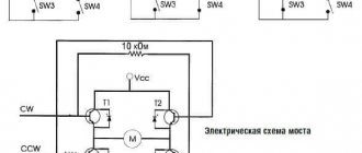
If one of the windings is turned off, the signal that was induced will be measured and further processed, however, this operating principle is impossible without a signal processing professor. But to reverse or brake such an electric motor, a bridge circuit is not needed - it will be enough to supply control pulses in reverse sequence to the stator windings.
In a VD (switched motor) an inductor in the form of a permanent magnet is located on the rotor, and the armature winding is on the stator. Based on the position of the rotor, the supply voltage for all windings of the electric motor is generated. When a collector is used in such designs, its function will be performed by a semiconductor switch in a switch motor.
The main difference between synchronous and valve motors is the self-synchronization of the latter using the DPR, which determines the proportional rotation speed of the rotor and the field.
Most often, brushless DC motors are used in the following areas:
- freezing or refrigeration equipment (compressors);
- electric drive;
- air heating, air conditioning or ventilation systems.
Stator
This device has a classic design and resembles the same device of an asynchronous machine. The composition includes a core of copper winding (laid around the perimeter in grooves), which determines the number of phases, and a housing. Usually the sine and cosine phases are sufficient for rotation and self-starting, however, the valve motor is often created as a three-phase or even four-phase one.
Electric motors with reverse electromotive force are divided into two types based on the type of winding on the stator winding:
- sinusoidal shape;
- trapezoidal shape.
In the corresponding types of motor, the electric phase current also changes according to the supply method, sinusoidally or trapezoidally.
Rotor
Ferrite magnets are considered the most common and cheapest for making a rotor, but their disadvantage is the low level of magnetic induction, so such materials are now being replaced by devices made from alloys of various rare earth elements, since they can provide a high level of magnetic induction, which, in turn, allows the rotor size to be reduced.
DPR
A rotor position sensor provides feedback. Based on the principle of operation, the device is divided into the following subtypes:
- inductive;
- photoelectric;
- Hall effect sensor.
The latter type has gained the greatest popularity due to its almost absolute inertia-free properties and the ability to get rid of delays in feedback channels based on the rotor position.
Control system
The control system consists of power switches, sometimes also of thyristors or power transistors, including an insulated gate, leading to a current inverter or voltage inverter assembly. The process of controlling these keys is most often implemented by using a microcontroller, which requires a huge number of computational operations to control the motor.
Launch of EPT with parallel excitation
When using this circuit, the armature winding and field winding are connected in parallel, which ensures the same potential difference. In this case, at start-up, a slightly lower current is supplied to the input of the auxiliary winding than to the stator/rotor windings.
To reduce the influence of starting characteristics on the equipment, the rheostat is activated immediately at start, reducing the load on the motor, and then turns off. If the start-up may be prolonged for various reasons, a circuit consisting of several starting resistors/rheostats is used:
In this case, the sequence of resistances Rstart1-Rstart3 allows you to reduce the current flowing through the windings to minimum values. As soon as the current reaches the threshold value, relays K1-K3 will operate, which will lead to the closure of contact K1.1. As a result, the first resistor will be bypassed, the current will increase abruptly, but due to the remaining resistors it will decrease again, and at the moment of minimum the next contact will close, and then the last one will close in the same way. At this point, the shaft rotation speed will reach the nominal speed.
When braking, the same circuit will work in the opposite direction.
What happens when you start the engine
As the current load on the stator winding increases, the torque of the electric motor increases, which is transmitted through the shaft to its moving part - the rotor. The faster the torque increases, the more the stator winding heats up.
This phenomenon can lead to:
- failure of insulation;
- the occurrence of vibrations;
- deformation of mechanical parts of the engine;
- complete failure of the motor.
High current can cause violent sparking under the brushes, which will lead to failure of the commutator.
You can avoid damage by reducing the starting current to the rated speed immediately after starting the electric motor. There are several ways to achieve this. The choice of the optimal option depends on the technical characteristics of the motor and its purpose.
Launching an EPT with sequential excitation
A special feature of using such a circuit for starting DC motors is the serial connection of a variable resistance and an excitation coil to the motor.
In this case, as in the previous one, a current of the same rating will flow through the circuit of both coils. This method is characterized by good starting characteristics, but on the condition that the electric motor shaft will be under load at this moment. And one more feature of an EPT with sequential excitation: the shaft rotation speed during startup will be adjusted depending on the load. This scheme is ideal for electric transport - trams, trolleybuses, with some modifications - on electric trains.
Schematic diagram of starting an EPT with sequential excitation:
Starting with a starting rheostat
In this case, a variable resistance is introduced into the circuit, which at the initial stage ensures a reduction in the current load until the rotation of the rotor reaches the set speed. As the amperage stabilizes to a standard value in the rheostat, the resistance decreases from the maximum value to the minimum.
The calculation of the electrical quantity in this case will be made according to the formula:
I = U / (Rexchange + Rrheostat)
In laboratory conditions, the load can be reduced manually - by moving the rheostat slider. However, this method is not widely used in industry, since the process is not consistent with current values. Therefore, adjustment by current, by EMF or by time is used, in the first case, the measurement of the value in the excitation windings is used, in the second, a time delay is applied to each stage.
Both methods are used to start electric motors:
- with sequential;
- with parallel excitation;
- with independent excitation.
Starting a DPT with parallel excitation
This start of the electric motor is carried out by turning on both the excitation winding and the armature to the power supply voltage; they are located in parallel relative to each other. That is, each of the windings of a DC electric motor is under the same potential difference. This starting method provides the hard operating mode used in machine tools. The current load in the auxiliary winding at start-up has a comparatively lower current than the stator or rotor windings.
To control the starting characteristics, resistances are introduced into both circuits:
Fig. 1. Starting a parallel-excited DC motor
At the initial stage of shaft rotation, the rheostat positions reduce the load on the electric motor, and then they are brought back to the zero resistance position. During long starts, automation and combination of several stages of starting rheostats or individual resistors are performed; an example of such a connection circuit is shown in the figure below:
Rice. 2. Stepped start of parallel motor
- When supply voltage is applied to the electric motor, the current flowing through the operating windings and the excitation winding is limited to a minimum value by the resistance store Rstart1, Rstart2, Rstart3.
- After reaching the threshold value of the minimum current value, relays K1, K2, K3 are sequentially activated.
- As a result of closing the contacts of relay K1.1, the first resistor is bypassed, and the operating characteristic in the power supply circuit of the electric motor increases stepwise.
- But after decreasing below the set limit, contacts K2.2 are closed and the process is repeated again until the electric machine reaches the rated speed.
Braking of a DC motor can be done in reverse order using the same resistors.
Starting a DPT with sequential excitation
Rice.
3. Starting a DC motor with sequential excitation The figure above shows a schematic diagram of connecting an electric motor with sequential excitation. Its distinctive feature is the series connection of the excitation coil Lexcitation and the motor itself; the variable armature resistance R is also introduced in series.
The same current flows through the circuit of both coils; this circuit has good starting parameters, so it is often used in electric vehicles. Such an electric motor must not be turned on without force on the shaft, and frequency control is carried out in accordance with the load.
Starting DPT with independent excitation
The electric motor is connected to a circuit with independent excitation by powering it from a separate source.
Rice. 4. Starting a DCT with independent excitation
The diagram shows an example of an independent connection; here the excitation coil L and the resistance in its excitation circuit R are powered separately from the motor windings by the current of an independent device. For the motor windings, the armature control rheostat R is also turned on. With this starting method, the DC machine should not be turned on without load or with minimal force on the shaft, as this will lead to an increase in speed and subsequent breakdown.
Starting EPT with independent excitation
Another way to start DC motors is to connect the EPT to the circuit by powering the latter from an independent power source.
In the example circuit shown, the coil and field resistor are powered separately from the motor windings. There is a control rheostat in the motor winding circuit.
This implementation also requires the presence of a load on the shaft at the time of start-up, otherwise an uncontrolled increase in speed will occur, fraught with motor breakdown.
Start by changing the supply voltage
One of the most complex is considered to be a scheme for reducing the starting load using a controlled rectifier or, as an option, a constant voltage generator, which is responsible for the task of reducing the supply current rating.
In principle, a rheostat copes with this task, but for high-power electric motors, the efficiency of the rheostat sharply decreases. Using a separate chip to change the supply voltage reduces losses.
The option with a generator or rectifier is used on electric power. high power motors. It has one more advantage: the possibility of reversal, which is realized by changing the direction of current flow in the armature.