Greetings to everyone on our website. Today we will talk about the design of a current generator. Let's try to cover this topic as much as possible and consider the design of direct and alternating current generators.
In fact, it is not entirely correct to call this device an alternating or direct current generator, since current occurs only in a closed circuit. In general, EMF, not current, occurs in the generator windings. Current begins to flow only when any consumer is connected to the windings. However, in this article we will use established concepts.
Whatever electric generators are, their main principle is the generation of electrical energy due to the rotation of the winding in a magnetic field. This means that we can distinguish two schematic types of generators: either we rotate a magnetic field in a stationary conductor, or we rotate a conductor in a stationary magnetic field.
Alternating current generator device
So, regarding the design of the alternator and the principle of its operation.
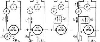
The most widespread are alternating current generators with a fixed conductor. This is due to the fact that the excitation current in relation to the current received from the generator is small. If you look at the picture, you will see two rings through which the excitation winding current flows and this is the weak link of any generator with an excitation winding. That is, either we supply a small excitation current through the rings through the brushes, or we remove a large operating current through the rings. In electricity, the stationary part of generators or motors that contains the winding is called the stator. The moving part may be called a rotor or armature.
Main types of alternating current generators
There are quite a few types of generators. Let's try to classify them according to their main areas.
- By type of energy used:
- Wind energy
- Liquid fuel energy
- Heat energy
- Water energy
Gas energy
- Single phase
Three-phase
There are other types, but they are less common.
- By type of excitation:
- Independent arousal. In this case, on the same shaft with the alternating current generator there is also a direct current generator, which powers only the excitation winding. In this case, excitation can be performed by any other current source, for example, a battery.
- Excitation using magnets that are located on the stator or armature, which greatly simplifies the design of the generator, but using this method it will not be possible to obtain powerful generators.
Self-excitation. In this case, the voltage for the field winding is obtained directly from the generator used.
Synchronous generator: circuit, device, principle of operation
What does synchronous mean in relation to a motor or generator? To put it very simply, the frequency of alternating current strictly depends on the rotation speed of the rotor of the electric machine and vice versa. In this way, the frequency of the alternating current can be controlled relatively easily. The synchronous generator itself has a number of advantages, thanks to which it has become the most widespread. I’ll tell you a big secret, it is synchronous generators that are used at all stations where electricity is produced.
The drive motor (designated as PD in the diagram) can be any rotating device: engine, turbine, windmill or water wheel impeller. On the same shaft with the PD there is a generator rotor with an excitation winding. A constant voltage is applied to the winding and a magnetic field is formed around the winding. When the rotor rotates, an EMF appears in the stator windings, that is, a voltage appears, only now variable, the frequency of which depends on the rotation speed of the rotor n1 and the number of pole pairs p. The EMF frequency can be calculated using the formula.
Asynchronous generator: circuit, device, principle of operation
Asynchronous generator device
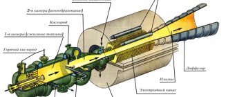
An asynchronous generator is essentially an asynchronous motor. That is, any asynchronous motor can be switched to energy generation mode and vice versa. Structurally, the device, which is called a generator, is designed in such a way as to have good cooling. We will not dwell deeply on the principle of operation of asynchronous machines, but I will briefly tell you why they are called asynchronous using the example of a motor.
When voltage is applied to the stator windings, a magnetic field is formed; for three-phase motors it is circular, for single-phase motors it is ellipsoidal, tending to be circular. The magnetic field begins to cross the turns of the stator winding. In the short-circuited winding of the rotor, an EMF arises, that is, voltage, and since the winding is short-circuited, a current begins to flow through it, which also creates a magnetic field. The interaction of these magnetic fields causes the rotor to move. What will happen if the speed of the rotor becomes equal to the speed of the magnetic field created by the stator? That's right, the stator magnetic field will stop crossing the rotor winding. This can be compared to two cars moving at the same speed. The cars seem to be moving, but at the same time, in relation to each other, they seem to be standing still, the ground is simply rushing under the cars at high speed. So, as soon as the rotor speed and the speed of the stator magnetic field become the same, EMF will no longer be generated in the rotor winding, the interaction of the magnetic fields of the stator and rotor will stop, and the rotor will begin to stop. Therefore, the rotation speed of the rotor of an asynchronous motor is always slightly less than the rotation speed of the stator magnetic field, and this value is called slip.
So, in order for an asynchronous motor to become a generator, it is necessary to determine the slip and increase the rotor speed by this amount. Let's say we have a single-pole three-phase asynchronous motor with a shaft rotation speed of 2800 rpm. If such a motor were synchronous, the rotation speed would be 3000 rpm. That is, the sliding is 200 revolutions per minute. This means that if we start rotating the rotor at a speed of 3200 rpm, the engine will switch to generator mode and will no longer consume, but generate EMF.
The difficulty of using such generators is that they are prone to failure. For example, if you turn on a resistive load (incandescent light bulb or heater), the inrush current will be small. Significant overload will not occur and the generator will operate stably. If you turn on a reactive load, for example, an engine, then there will be a large starting current, 5-20 times higher than the rated current, which will “fail” the generator, that is, cause a sharp drop in voltage on the generator windings. After such a failure, the asynchronous generator must be excited again. So, the simplicity of an asynchronous generator is outweighed by a serious drawback.
Well, you also need a capacitor unit to excite the short-circuited rotor winding. If we choose the wrong capacitance of the capacitors, then in case of “undersupply” from the generator we will receive less current, and in case of “oversupply”, our generator will overheat greatly.
Connection diagrams
Actually, not even switching schemes, but options. There are usually three of them:
- Automatic switching on . In this case, a special emergency switching unit is installed. As soon as the voltage in the network is turned off, the unit sends a command to start the generator and switches the network from an external power source to the generator set.
- Manual activation . In this case, the user himself carries out the switching operation from the external power source to the generator set and manually starts the generator.
- Synchronous work . This mode is mainly used at large stations, the generators of which are combined into one network. All generators of this network operate synchronously, with the same frequency, with the same phase order and with the same voltage on the stator windings.
Single phase generator
I won't go into detail here. Such devices can now be found in any tool store. If a single-phase generator is used as a backup source of electricity, it is connected to the home network, usually through a switch. That is, an external power source and a generator cannot operate on the same network at the same time - it’s either one or the other. Firstly, there is no need, and secondly, it would greatly complicate and increase the cost of household generators. The only thing I can focus on here is connecting a single-phase generator to a three-phase network.
Connecting a single-phase generator to a three-phase network
However, this method has its drawback. Three-phase motors will not work in such a network; if you turn them on, they will heat up very quickly and fail.
Three phase generator
Three-phase generators can be domestic and industrial. The design of a three-phase current generator in the household version is practically no different from a single-phase one, as is the switching circuit. The only condition when connecting a household generator to a network, if there are three-phase motors in such a network, is to observe the phase order. If the load in the house is single-phase, then this precaution can be neglected.
The industrial version of a three-phase current generator device is a device equipped with an automatic start and can sometimes be equipped with a synchronization device. It is better to entrust the connection of such generators to specialists.
Well, a household generator, just like a single-phase generator, is connected to the network through a switch. Consequently, depending on the position of the switch, either an external power source or a generator operates.
Independent excitation generators
Definition. Independent excitation generators are called direct current generators, the excitation winding of which is powered by direct current from an external source of electrical energy (DC network, rectifier, battery, etc.) or in which the magnetic flux is created by permanent magnets.
Generator circuit. The circuit of the independent excitation generator is shown in Fig. 1.16. The generator armature is driven into rotation by the PD drive motor.
The armature circuit is not electrically connected to the excitation circuit, therefore the load current I and the armature current Iа are the same current (I = Iа). The excitation circuit is powered by an external DC source. It includes an adjusting rheostat R p, designed to regulate the excitation current Ib, the excitation magnetic flux and, ultimately, the emf and voltage of the generator.
Characteristics of idle speed (Fig. 1.17). The characteristic is removed with a smooth increase in the excitation current, and then with its smooth decrease at n = nnom = const. The second branch of the characteristic goes slightly higher than the first and at current Iв = 0 in the machine there is some EMF E0, called residual. The type of idle speed characteristic is explained by the fact that when n = const E = CenФ is proportional to the magnetic flux Ф, and the latter is proportional to the induction B, i.e. its shape is the same as that of the hysteresis curve. The characteristic passing between the branches of the experimental curve is usually taken as the calculated one (dashed curve in Fig. 1.17). The residual EMF E0 is created due to the induction remaining in the stator magnetic circuit after the excitation current is turned off. The machine is calculated in such a way that in the nominal mode the operating point (Iv.nom, Enom) is located on the “knee” of the no-load characteristic, this ensures that a sufficiently high EMF is obtained with a relatively small excitation current.
External characteristics. The external characteristic of the generator U = f(I) with IB = const and n = nnom = const (Fig. 1.18) characterizes the influence of the generator load current on the voltage at its terminals. Voltage U = E – RЯ I, when the load increases from zero to nominal, smoothly decreases by 5–15% for two reasons: due to the voltage drop across the armature resistance RЯ I and the decrease in emf E due to the demagnetizing effect of the armature reaction (curves 1 and 1a ). When the machine is overloaded, the current in the armature becomes unacceptably large and the voltage drops significantly (curve 1a).
During a short circuit, the current in the armature Ik is approximately 10 times greater than the rated one (it is limited only by the resistance of the armature circuit 1k = E / RЯ) and if the generator is not quickly turned off, its collector and winding will fail.
Regulating characteristic. The control characteristic Iв = f(I) at U = const and n = nn = const is shown in Fig. 1.19 (curve 1). To maintain a constant voltage at the armature terminals, an adjusting rheostat with resistance Rp is included in the excitation circuit (Fig. 1.16).
DC generator device
To find out what a DC generator is, its structure and principle of operation, let’s go back a little. We have already figured out how an alternator works. Let's take a closer look at the process of EMF generation. As the rotor rotates, we have a cycle equal to one revolution of the rotor, or 360°. Let's find out what happens in this cycle:
- 0° - EMF =0
- 90° - EMF reaches its maximum value with the “+” sign
- 180° - EMF is again 0
- 270° - EMF reaches a peak value with a “-” sign
How to make sure that the polarity of the voltage does not change? Great minds came up with the following idea - to use a collector, that is, to remove voltage only of the required polarity. Remember, we said that in an alternating current generator, the stator winding is the working one, and the excitation winding is located on the rotor. So, in a DC generator, voltage is removed only from the rotor, which is called the armature.
DC generator circuit
If such a generator has only one pair of poles, as in the picture, then we will get a pulsating direct voltage, where the frequency will be twice the rotation speed. That is, if the rotation speed is 50 revolutions per second, then the pulsation frequency will be 100 Hz. To reduce voltage ripple, increase the number of pole pairs.
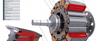
Since the invention of the DC generator, it has remained virtually unchanged schematically and in principle of operation, only the manufacturing technology has changed and now it looks like this:
Main types of DC generators
Currently, commutatorless DC motors are gaining popularity. Is a brushless generator option possible? Unfortunately, we have not yet been able to solve this problem. So, if you see the name “Brushless DC Generator” somewhere, know that it is an AC generator with a rectifier unit.
For this reason, DC generators are characterized only by the type of excitation:
- Generators excited by magnets . Such generators cannot develop high power, so they are used only where small power is required. And, of course, the use of magnets significantly reduces the cost of such generators.
- Independent arousal. In the same way as with alternating current generators, an external power source not connected to the generator is used for excitation.
- Dependent arousal, which is divided into three types:
- Parallel excitation. As the name suggests, the excitation winding in such a generator is connected in parallel to the armature winding. Sometimes this type of excitation is called shunt.
- Consistent excitation. Here the excitation winding is connected like a garland, in series with the armature winding. This type is sometimes called serial.
- Mixed or compound excitation. The excitation winding of such generators consists of two parts, the first is connected by a shunt method, the second by a serial method.
Generators with independent excitation: circuit, device, principle of operation
Independent excitation generator circuit
The operating principle of this generator is quite simple. However, the simplicity of the generator is also its disadvantage - it requires an external independent power source. The generator armature is accelerated to the required speed, then the generator is excited using a rheostat. An EMF appears on the armature windings and when a load is connected, current begins to flow.
The load capacity of such a generator is very good. As a rule, the difference between the no-load voltage, when the load is not connected, and the voltage at the rated load of the generator, when the consumer is fully loading, is only 5-10%.
The advantage of a generator with independent excitation is that it can be started under load, that is, with electrical appliances connected.
Generators with parallel excitation: circuit, device, principle of operation
Parallel excitation generator circuit
A generator with a parallel connection of the excitation winding, in principle, also has good load characteristics, although somewhat worse than those of circuits with independent excitation - 10-30%. Circuits with dependent excitation have one feature: in order for excitation to occur, the metal of the generator must have residual magnetization. 2-3% of residual magnetization is enough to start the self-excitation process. Of course, in this case the direction of the excitation winding must coincide with the direction of the residual magnetization field.
The generator armature is spun up to rated speed, due to residual magnetization self-excitation occurs, that is, an EMF appears in the generator-excitation winding circuit and a small current appears. It increases the EMF, therefore the current increases again and this happens until a balance is reached between the voltage drop in the generator winding and the voltage drop in the field winding.
There is one peculiarity in the operation of the generator. If you gradually increase the load until a short circuit occurs, then at some point the generator power will reach peak values, then begin to decline. In fact, if you create a short circuit at the moment of nominal load of the generator, then nothing bad will happen. But if this is done with a small load, then the short circuit current reaches critical values of 8-10 In, which means that such generators are highly recommended to be protected from short circuits by any available method.
Such generators are most widespread because they do not require external power supplies, have good load capacity and allow control of the excitation current.
Generators with sequential excitation: circuit, device, principle of operation
Series excitation generator circuit
Since the current of the excitation winding in this case is equal to the current in the circuit, and therefore reaches large values, the excitation winding is made of thick wire and has fewer turns than in the previous two circuits. The operating principle is the same as the previous scheme. The winding and the residual magnetization field must coincide in direction. When the armature is untwisted to the rated frequency, an EMF occurs, the current rises and further increases until balance is achieved.
But there is one small nuance here. The field winding current varies depending on the load current, and there is no way to regulate the field current. And this leads to the fact that the voltage also changes greatly. Here we get a real current generator, not a voltage generator. That is why the scope of application of a generator with series excitation is very limited.
Parallel excitation generator
Electrical machines › DC electric machines
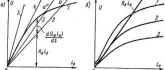
The principle of self-excitation of a direct current generator is based on the fact that the magnetic system of the machine, being magnetized, retains for a long time a small magnetic flux of residual magnetism of the pole cores and Fost frame (about 2-3% of the total flux). When the armature rotates, the flow
Rice. 28.5. Schematic diagram (a) and characteristics of the x.x. (b) parallel excitation generator
induces EMF Eost in the armature winding, under the influence of which a small current Iv.ost appears in the excitation winding.
If the MMF of the excitation winding Iv.ost wB has the same direction as the flux Fost, then it increases the flux of the main poles. This, in turn, causes an increase in the EMF of the generator, causing the excitation current to increase again. This will continue until the generator voltage is balanced by the voltage drop in the excitation circuit, i.e. U0 = IВrВ.
In Fig. 28.5, a
shows the connection diagram of the parallel excitation generator, in Fig.
28.5, b
- characteristics of x.x.
generator (curve 1
) and the dependence of the voltage drop on the excitation current IВrВ = F(IВ) (straight line
2
).
Intersection point A
corresponds to the end of the self-excitation process, since it is there that U0 = IВrВ.
Angle of inclination of straight line OA
to the abscissa axis is determined from the triangle OAB
, (28.10)
where mi is the current scale (along the abscissa), A/mm; mu—voltage scale (along the ordinate), V/mm.
From (28.10) it follows that the angle of inclination of the straight line IВrВ = F(IВ) to the abscissa axis is directly proportional to the resistance of the excitation circuit. However, at a certain value of the rheostat resistance rрг, the resistance rB reaches a value at which the dependence IВrВ = F(IВ) becomes tangent to the straight part of the x.x characteristic. (straight 3
)
.
Under these conditions, the generator does not self-excite.
The resistance of the excitation circuit, at which self-excitation of the generator stops, is called critical
resistance (
rB.crit).
It should be noted that self-excitation of the generator is possible only at a rotation speed exceeding the critical nkt. This condition follows from the self-excitation characteristic the generator ( Fig on the rotational speed with a constant resistance of the excitation circuit, i.e. U0 = F(n) at rB = const.
Rice. 28.6. Self-excitation characteristic
Analysis of the self-excitation characteristics shows that for n < ncr, an increase in the rotation frequency of the generator armature is accompanied by a slight increase in voltage, since there is no self-excitation process and the appearance of voltage at the generator output is due only to the residual magnetization of the generator magnetic circuit. The self-excitation process begins at n < ncr. In this case, an increase in rotation speed is accompanied by a sharp increase in voltage U0 .
However, at a rotation speed close to the nominal one, the voltage increase slows down somewhat, which is explained by the magnetic saturation of the generator. The critical rotation speed depends on the resistance of the excitation circuit and increases as the latter increases.
Thus, self-excitation of DC generators is possible subject to the following conditions: a) the magnetic system of the machine must have residual magnetism; b) the connection of the field winding must be such that the MMF of the winding coincides in direction with the flow of residual magnetism Fost; c) the resistance of the excitation circuit must be less than critical; d) the armature rotation frequency must be greater than the critical one.
Since the parallel excitation generator is self-excited in only one direction, the x.x. of this generator can only be taken for one quadrant of the coordinate axes.
The load and control characteristics of the parallel excitation generator practically do not differ from the corresponding characteristics of the independent excitation generator.
External characteristics of parallel excitation generator 1
(Fig. 28.7) less rigid than that of an independent excitation generator.
This is explained by the fact that in a parallel excitation generator, in addition to the reasons that cause a decrease in voltage in the independent excitation generator (armature reaction and voltage drop in the armature circuit), there is also a third reason - a decrease in the excitation current caused by a decrease in voltage from the action of the first two reasons. This also explains the fact that with a gradual decrease in load resistance rn, the current increases only up to a critical value Icr, and then with a further decrease in load resistance, the current begins to decrease. Finally, the load current during a short circuit is Ik < Icr. The fact is that with increasing current, demagnetization of the generator increases (increased armature reaction and decreased excitation current), the machine goes into an unsaturated
state, in which even a small decrease in load resistance causes a sharp decrease in the EMF of the machine (see Fig. 28.5,
b
)
.
Since the current is determined by the voltage at the terminals of the generator U and the load resistance rn, i.e. I = U/rn, then at load currents I < Icr, when the generator voltage decreases more slowly than the load resistance decreases, the load current increases. After I = Icr, a further decrease in rn is accompanied by a decrease in the load current, since in this case the voltage U decreases faster than the load resistance rn decreases.
Rice. 28.7. External characteristics of the parallel excitation generator
Thus, a short circuit caused by a slow decrease in load resistance is not dangerous for the parallel excitation generator. But with a sudden short circuit. the magnetic system of the generator does not have time to demagnetize and the current Ik reaches values that are dangerous for the machine Ik = (8–12)Inom (curve 2
). With such a sharp increase in load current, a significant braking torque occurs on the generator shaft, and strong sparking appears on the collector, turning into a circular fire. Therefore, it is necessary to protect the generator from overload and short circuit. using fuses or using relay protection.
Parallel excitation generators are widely used in direct current installations, since the absence of an exciter distinguishes these generators favorably from independent excitation generators. The nominal voltage change of the parallel excitation generator is 10-30%.