Installation of SIP using an aerial platform
SIP suspension
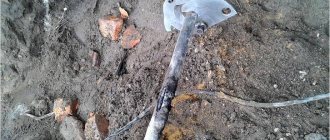
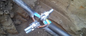
Re-grounding installation
0.4 kV overhead power lines are installed from 10/0.4 kV transformer substations to the consumer and consist of 4 insulated SIP wires (3 phases). The length of the overhead line must comply with the specifications for voltage quality, uninterrupted power supply, and economic indicators. An automatic device is installed at the consumer input to limit power consumption.
The experience of using 0.4 kV power lines with bare wire has proven their unsafety. This is due to the likelihood of electric shock when the overhead line breaks. Difficult weather conditions cause frequent short circuits of the exposed wire. To avoid these problems, a new type of wire was developed - SIP (self-supporting insulated wire).
Types of SIP for overhead lines
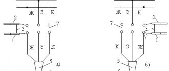
The SIP wire is made of aluminum conductors, separately coated with UV-resistant insulation. Several types are used for VLI:
- SIP – 1 – self-supporting wire with aluminum conductors, insulated from light-stabilized cross-linked polyethylene (PE), with a zero load-bearing uninsulated conductor made of aluminum alloy;
- SIP – 2 – self-supporting wire with aluminum cores, insulated with light-stabilized cross-linked polyethylene, with a zero load-bearing core, made of aluminum alloy, insulated with light-stabilized cross-linked PE.
- SIP – 3 – self-supporting protected wire with a current-carrying core made of aluminum alloy, with protective insulation made of light-stabilized cross-linked PE.
- SIP – 4 – self-supporting insulated wire without a supporting element, with aluminum conductors, with insulation made of light-stabilized cross-linked PE. If there is a water blocking element, the letter “g” is added to the wire grade.
- SIP - 5 - all cores have an insulating cover made of cross-linked light-stabilized polyethylene (polyethylene with cross-linked molecular bonds). The wire may consist of 2 or more cores. In the design of the SIP-5 wire there is no separate load-bearing core.
Technical dictionary: letter v
TECHNICAL DICTIONARY
A B C D E F G H I J J K L M N O P R S T U V X C CH W Y Z ABCDEFGHIJKLMNOPQRSTU VWXYZ 0-9 VA - (VA) is a unit of measurement of total electrical power, accepted letter SI designation - S. Unit of measurement VA (VA) Volt-Amperes Volt-Ampere.
Total electrical power is the geometric sum of active and reactive power, found from the relation – S2=P2+Q2. Either from the following relationships: S=P/cosph or S=Q/sinph Varicap is a semiconductor diode with a capacitance that depends on the applied reverse voltage; intended for use as an element with electrically controlled capacitance
Varikond is a ferroelectric ceramic capacitor with a sharply nonlinear dependence of the capacitance on the applied electrical voltage.
Watt - (designation: W, W) - in the SI system, a unit of measurement for Active power. The unit is named after the Scottish-Irish inventor-mechanic James Watt (Watt) Input-distribution devices - an input device, which also includes devices and devices of outgoing lines, is called an input-distribution device (IDU) [PUE clause 7.1.3.] Input - distribution devices - a low voltage electrical device containing equipment that provides the ability to input, distribute and account for electricity, as well as control and protect outgoing distribution and group electrical circuits in residential and public buildings, which is replaced in the form of corresponding functional blocks in one or more connected between panels or in one cabinet, depending on the type of building [SP 256.1325800.2016] Input device (ID) - a set of structures, devices and instruments installed at the input of the supply line into the building or into a separate part of it [SP 256.1325800.2016] Input device (ID) is a set of structures, devices and instruments installed at the input of the supply line into the building or its separate part. The input device, which also includes devices and devices of outgoing lines, is called an input-distribution device (IDU) [PUE clause 7.1.3.] VDT with a shutdown time delay - VDT, specially designed to ensure a predetermined value of the maximum non-shutdown time corresponding to a given value of differential current [GOST R 51326.1-99] RCCB with free tripping - RCCB whose moving contacts return to the open position and remain in this position if the shutdown command is received after the start of the closing operation, even if the closing operation continues . NOTE To ensure reliable interruption of any current that might build up, it may be necessary for the contacts to briefly assume the closed position. [GOST R 51326.1-99] RCCB type A - RCCB whose operation is ensured by both sinusoidal alternating and pulsating direct differential currents by either sudden application or slow rise [GOST R 51326.1-99] RCCB type AC - RCCB whose operation is ensured by differential sinusoidal alternating current by either its sudden application, or with a slow increase [GOST R 51326.1-99]
Rolling shutdown is a restriction (full or partial) of the mode of electrical energy consumption due to technological reasons, including its level, for reasons not related to the execution consumer of electrical energy of its contractual obligations or the technical condition of its energy receiving devices and (or) power installations (hereinafter referred to as energy receiving devices)
Explosive zone - part of a closed or open space within which flammable substances are constantly or periodically circulating and in which they can be located during normal mode of the technological process or its disruption (accident) [Federal Law dated July 22, 2008 N 123-F3] and fire hazard of the protected object is the state of the protected object, characterized by the possibility of an explosion and the development of a fire or a fire and subsequent explosion [Federal Law dated July 22, 2008 N 123-F3]
VZU - water intake unit - engineering and technical complex of buildings and equipment for autonomous water supply of objects for various purposes
Visible radiation is electromagnetic radiation that causes visual sensation and occupies the spectrum region from 380 to 780 nm.
Light emissions of different frequencies are perceived by humans as different colors VL - a power transmission line, the wires of which are supported above the ground using supports and insulators [GOST 24291-90] VL - a device for transmitting electricity through wires located in the open air and attached using insulators and fittings to supports or brackets and racks on engineering structures (bridges, overpasses, etc.). For the beginning and end of an overhead power transmission line, linear portals or linear inputs of the switchgear are taken, and for branches - a branch support and a linear portal or linear input of the switchgear [POTEU] VL - (Overhead line) power transmission with voltage up to 1 kV - a device for transmitting and distributing electricity along insulated or non-insulated wires located in the open air and attached by linear fittings to supports, insulators or brackets, to the walls of buildings and to engineering structures. An overhead power line with voltage up to 1 kV using self-supporting insulated wires (SIP) is designated VLI. Self-supporting insulated wire - insulated conductors twisted into a bundle, and the supporting conductor can be either insulated or non-insulated. The mechanical load can be perceived either by the load-bearing core or by all conductors of the harness. (PUE 2.4.2.). An overhead power line above 1 kV is a device for transmitting electricity through wires located in the open air and attached using insulating structures and fittings to supports, load-bearing structures, brackets and racks on engineering structures (bridges, overpasses, etc.). (PUE 2.5.2.) Wet rooms - rooms in which the relative air humidity is more than 60%, but does not exceed 75% [PUE 1.1.7.] VLZ - overhead power line carried out by wires with a protective insulating sheath - protected wires (VLZ) . (PUE 2.5.1.) However, the entry VLZ-6(10) kV is often found. (Author's note) [PUE 2.5.1.] VLI - an overhead power line with voltage up to 1 kV using self-supporting insulated wires (SIP) is designated VLI. (PUE 2.4.2.). However, it is often designated in documents as VLI-0.4 kV. (Author's note) [PUE 2.4.2.] VLS - overhead communication line [POTEU]
Concave lens - synonyms: diverging lens.
A lens, the central part of which is thinner than the edges, as a result of which parallel rays of light incident on the lens diverge when leaving it. Overhead line - (OHL) a device for transmitting electricity through wires located in the open air and attached to supports using insulators and fittings or brackets and racks on engineering structures (bridges, overpasses, etc.). For the beginning and end of an overhead power transmission line, linear portals or linear inputs of the switchgear are taken, and for branches - a branch support and a linear portal or linear input of the switchgear [POTEU ] . insulated or non-insulated wires located in the open air and attached by linear fittings to supports, insulators or brackets, to the walls of buildings and to engineering structures. An overhead power line with voltage up to 1 kV using self-supporting insulated wires (SIP) is designated VLI. Self-supporting insulated wire - insulated conductors twisted into a bundle, and the supporting conductor can be either insulated or non-insulated. The mechanical load can be perceived either by the load-bearing core or by all conductors of the harness. (PUE 2.4.2.). An overhead power line above 1 kV is a device for transmitting electricity through wires located in the open air and attached using insulating structures and fittings to supports, load-bearing structures, brackets and racks on engineering structures (bridges, overpasses, etc.). (PUE 2.5.2.) Overhead line - (overhead) power line, the wires of which are supported above the ground with the help of supports, insulators [GOST 24291-90] Overhead electrical network - electrical network that has only overhead power lines [GOST 24291-90] Air gap is the shortest distance in air between two current-carrying parts [GOST R 51326.1-99] Air transformer is a dry, unsealed transformer in which atmospheric air serves as the main insulating and cooling medium [GOST 16110-82]
Waveguide is a channel in a heterogeneous medium along which directed electromagnetic radiation can propagate. They are distinguished by shielded waveguides formed by specularly reflective walls
Fiber optics is a branch of optics that studies the propagation of light in light guides.
Volt-Ampere - (VA) is a unit of measurement of total electrical power, the accepted SI letter designation is S. Unit of measurement VA (VA) Volt-Ampere Volt-Ampere. Total electrical power is the geometric sum of active and reactive power, found from the relation – S2=P2+Q2. Either from the following ratios: S=P/cosф or S=Q/sinф VPT - (DC insert) - a converter substation designed to convert alternating current into direct current and subsequent conversion of direct current into alternating current of the original or other frequency [GOST 24291-90 ] RCCB tripping time is the time interval between the moment of sudden occurrence of the tripping differential current and the moment of arc extinguishing on all poles [GOST R 51326.1-99] Opening time - (opening time): time measured from the moment when the circuit breaker is in the closed position , the current in the main circuit reaches the level of operation of the overcurrent release, until the arcing contacts in all poles are disconnected. Note - The opening time is usually called the release time, although, more precisely, the release time refers to the interval between the initial moment of opening and the moment when the opening command becomes irreversible [GOST R 50345-2010] VRU (Input distribution device) - low voltage electrical device , containing equipment that provides the ability to input, distribute and account for electricity, as well as control and protect outgoing distribution and group electrical circuits in residential and public buildings, which is replaced in the form of corresponding functional blocks in one or more interconnected panels or in one cabinet, depending on the type of building [SP 256.1325800.2016] IDU (Input distribution device) - the input device, which also includes devices and devices of outgoing lines, is called input distribution device (IDU) [PUE clause 7.1.3.] There are three designs of input distribution devices (GOST 51732-2001): - a multi-panel ASU is a device whose functional blocks are located in several panels. The number of these blocks is determined by the composition and number of devices required for a specific electrical installation of a residential building or public building; — a single-panel ASU is made on the same structural basis as the panels of a multi-panel ASU. A single-panel ASU contains all the functional blocks necessary for the electrical installation of a building or its individual parts; - a cabinet ASU contains the required functional blocks for the electrical installation of a house or cottage, built into a cabinet-type shell Auxiliary core - an insulated current-carrying core as part of a stranded wire for connecting external lighting or control circuits [GOST 31946-2012] Auxiliary circuit of the NKU - all current-carrying parts of the NKU, included in a circuit intended for control, measurement, signaling, regulation, data processing and transmission, etc. and not being the main circuit [GOST 28668-90 (IEC 439-1-85)] DC insert (DCI) - a converter substation designed to convert alternating current into direct current and subsequent conversion of direct current into alternating current of the original or another frequency [GOST 24291 -90] Built-in substation (Built-in transformer substation) - an electrical substation that occupies part of the building [GOST 24291-90] W - (designation: W, W) - in the SI system, the unit of measurement of Active power. The unit is named after the Scottish-Irish mechanical inventor James Watt (Watt) Secondary system of a power plant [substation] - a set of control, signaling, automation, protection and measurement devices of a power plant [substation], interconnected by secondary circuits [GOST 24291-90] Secondary circuit of a power plant [substation] - a set of cables and wires connecting control, automation, signaling, protection and measurement devices of a power plant [substation] [GOST 24291-90] Rectifier substation - a converter substation designed to convert alternating current into direct current [GOST 24291-90 ]
Convex lens - a lens whose central part is thicker than the edges, as a result of which parallel rays of light incident on the lens converge when leaving it
Potential equalization - providing an electrical connection between the exposed conductive part and the conductive parts (conductors) located in the ground or conductive floor , designed to provide a similar potential between an open conductive part that can be touched by a person or animal, and the surface of the earth or conductive floor [GOST R IEC 61140-2000] Potential equalization - reducing the potential difference (step voltage) on the surface of the earth or floor using protective conductors laid in the ground, in the floor or on their surface and connected to a grounding device, or by using special ground coverings [PUE 1.7.33.] Potential equalization that ensures protection - potential equalization that ensures safety [GOST R IEC 61140 -2000] High voltage - 220 kV, 110 kV - HV, High voltage [More details in the article] High voltage - voltage, the nominal root mean square value of which exceeds 35 kV, but does not exceed 220 kV [GOST 32144-2013] WPP - Eastern Electric Networks – branch of PJSC “MOESK”. Address: 142407, Moscow region, Noginsk, st. Radchenko, 13. The service area includes the following districts of the Moscow region: Noginsk; Orekhovo-Zuevsky; Shchelkovsky; Balashikhinsky; Kolomensky; Lukhovitsky; Zaraisky; Ozersky; Shatursky; Egoryevsky; Pavlovo-Posadsky*; Voskresensky*. Note: in Orekhovo-Zuevsky, Balashikha, Zaraisky, Pavlovo-Posad, Voskresensky, Lukhovitsky, Ozersky and Shchelkovsky districts of electrical networks, customer service is not provided. Residents of these areas should contact any electrical customer office. More detailed information on the settlements served with contacts for applications to the wind farm is provided on the Official website of PJSC "MOESK"
Construction of overhead lines
A trained team is allowed to carry out construction. All electrical installation work is carried out according to standard maps, or according to a project developed and agreed upon with the customer. Construction work includes:
- Development of pits and installation of supports;
- Installation of wires and grounding devices.
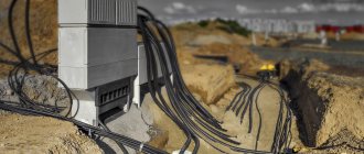
At the beginning of the work, the route is cleared for installing supports and rolling out the wire. If the construction of an overhead line is carried out on an old route, then the old supports are first dismantled. The SIP wire is rolled out along the installed new supports so as not to damage the insulation. A team of electricians lifts the wire onto the supports and installs fittings and grounding devices.
Load of overhead lines with SIP wires
Wires insulated with thermoplastic polyethylene are allowed for long-term heating up to 70°C, and short-term heating during short circuit up to 130°C. Wires insulated with cross-linked polyethylene should not exceed the temperature of long-term heating more than 90°C and short-term heating - 250°C, when shorted. The duration of the load on the wire depends on its cross-section and ambient temperature. Every year, according to the schedule, the load on isolated overhead lines is measured and the results are recorded in the overhead line passport.
Requirements for 0.4 kV overhead lines:
The 0.4 kV overhead line must be made in a three-phase 4-wire design in a radial design with wires of the same cross-section along the entire length of the line (main) from 10/0.4 kV substations.
0.4 kV overhead lines are made only using self-supporting insulated wires.
The length of lines should be limited by technical specifications in terms of voltage quality, reliability of power supply to the consumer and economic indicators (technical losses of electricity in the line and the costs of its distribution).
Install devices at the inputs to subscribers to limit power consumption (joint work with an energy sales organization). Power limiting devices must ensure automatic disconnection of the subscriber from the electrical network in the event of exceeding the power of his electrical installations and switching back on with a time delay.
Grounding of overhead lines
To ensure safety, uninterrupted operation and protection from lightning, the 0 kV power line must be grounded.
Lightning protection grounding is installed every 120 m on supports, as well as:
- on a support with entry into a room where a large number of people live or have agricultural value;
- on the final support with an inlet branch;
- on a support installed 50m from the end of the line;
- on a support with the intersection of high voltage lines.
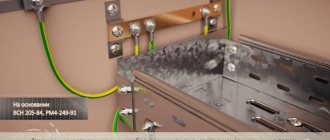
Grounding is carried out on all metal structures, switchboards, and street lamps.
For the manufacture of grounding, a wire with a diameter of 6 mm with an anti-corrosion coating is used.
Installation of cable lines 6 kV and 10 kV
Hello again!
Today I want to show an example of calculating estimates for 6 kV and 10 kV cable lines. I want to combine these two topics, since in these works everything is absolutely the same - only the materials change, for example:
1. Cable ASB-6 3Х185 (ozh) – 6 kV cable;
2. Power cable ASBL 3*150(ozh)-10 – 10 kV cable
3. Cable AAShv-10 3Х120 - 10 kV cable.
Designations may be different, since each cable manufacturer has its own cable marking.
Cable end sleeves and connecting sleeves are marked the same and are designated:
1. Cable connecting coupling 10STp(tk)-3x(70-120) with bolted connectors - connecting coupling for three-core power cable 6-10 kV with a cross-section from 70 to 120 mm2;
2. Cable end coupling 10KVTpN-3x(150-240) with bolted lugs - end coupler for internal installation for three-core cable 6-10 kV with a cross-section from 150 to 240 mm2.
So, we have figured out the difference in drawing up estimates for a 6 kV cable line and a 10 kV cable line, now let’s look at an example:
Fig.1. Plan of the KL-6kV route.
In this drawing we see that trench T-9, according to the standard design A5-92-13 (I will not lay out the dimensions of the trench and the standard design here, since we discussed in detail in the previous article CL-0.4 kV), the cable line is laid in 2 threads (this can be seen in the sections of trench 1-1, 2-2), cable ASbL-6-3x150 mm2, then the cable goes into six single-core cables of the APvPg-6-1x150/50-6 brand using adapter couplings TRAJ12/1x150- 240. The cable is laid in a pipe using the puncture method (HDD) through railway tracks, through an asphalt concrete road (disassembly, restoration).
Fig.2. Specification
In the specification, we already see in detail the quantity and grade of materials that are necessary to complete the work.
What difficulties may arise when drawing up estimates:
1) it is necessary to determine the amount of cable laid in a trench, pipe, by structure, and if there are several brands of cable, determine the weight for each cable and which one is laid how;
2) installation of cable couplings - for example - we have couplings for single-core cable, but there are no prices, I apply the usual price for 3-4 core cables and divide by 3:
Perhaps this is wrong and many large customers do not skip these prices at all, even for standard couplings, but if you take end seals, it turns out very cheap, and in terms of the cost of work (if you compare prices with private owners), the installation of end couplings actually costs less than connecting ones, but for some reason, according to the prices, installation of an end coupling is an order of magnitude more expensive (it contains a “Telescopic Tower” at the rate of 6.4 hours per 1 coupling!!!, this is a lot), but as we know, it is undesirable to adjust prices down or up and that’s all prices are averaged, that is, if we do not get the amount for the installation of couplings, we are compensated for the amount of the cost of work on the installation of end couplings (if we install only end couplings, we exclude towers from resources, this is what we practice in our organization).
I would like to hear your opinion, how the examination misses you, large customers, write, share your experience.
3) Soil development - according to the correct method, we should develop part of the soil with loading onto dump trucks and remove this soil, this is the soil that is replaced by sand or fine sifted earth, but in our case the volume is not so large and the territory is private, and there is excess soil it is simply leveled on the territory;
4) They don’t always skip the quote “Establishment of a bed with one cable in a trench”; instead they ask to use soil group 1 backfilling of the trench;
5) One Customer, when backfilling a trench, asked to use soil 1 group lower, supposedly it was loosened and lighter, but in 10 years, I was only given such a remark once...
6) “Heat-shrinkable sealant for cable passages (190-55mm) UPTK-2”, almost all Customers ask to apply the price “Sealing passages when introducing cables into premises with a sealing mass”, I think that this is a slightly different job and I use the price from the 10th installation collection GESNm10-06-034-28 “Sealing of cable duct: occupied”.
Yes, and my estimate was compiled according to the old prices; in the next article I will review the changes on the new basis.
I look forward to your comments, how they miss you, write and we’ll discuss it!
Below I am attaching files with estimates, the first estimate for this project, the rest - in addition, as examples.
Files:
Estimate for installation of 6 kV cable lines from TP-4.xlsx (44.13 KB)
Removal of the power supply network 10 kV .xlsx (20.3 KB)
Estimate for installation of CL-6kV.xlsx (28.55 KB)
Acceptance and testing of overhead lines
Before putting into operation, all overhead lines are accepted in accordance with the rules and are subjected to testing, including:
- Spot check of 2 to 15% of fittings, contacts and connections;
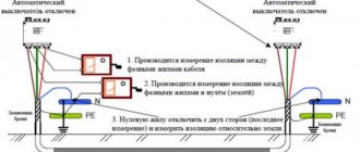
- Checking the conductor markings on the terminals;
- A 1000 V megohmmeter measures the insulation resistance of SIPs, which must be at least 0.5 MOhm;
- A 2500 V megohmmeter is used to test high voltage insulation for breakdown;
- Inspection and testing of all grounding devices and their connections;
- Checking the sag of SIP booms.
If violations are detected, the VLI is not accepted for operation.